EP1014356B1 - Appareil d'enregistrement / de reproduction de bande magnétique - Google Patents
Appareil d'enregistrement / de reproduction de bande magnétique Download PDFInfo
- Publication number
- EP1014356B1 EP1014356B1 EP99310342A EP99310342A EP1014356B1 EP 1014356 B1 EP1014356 B1 EP 1014356B1 EP 99310342 A EP99310342 A EP 99310342A EP 99310342 A EP99310342 A EP 99310342A EP 1014356 B1 EP1014356 B1 EP 1014356B1
- Authority
- EP
- European Patent Office
- Prior art keywords
- capstan
- support plate
- magnetic tape
- motor support
- supporting
- Prior art date
- Legal status (The legal status is an assumption and is not a legal conclusion. Google has not performed a legal analysis and makes no representation as to the accuracy of the status listed.)
- Expired - Lifetime
Links
- 230000006835 compression Effects 0.000 description 4
- 238000007906 compression Methods 0.000 description 4
- 238000010586 diagram Methods 0.000 description 4
- 238000006073 displacement reaction Methods 0.000 description 4
- 230000000284 resting effect Effects 0.000 description 2
- 238000005452 bending Methods 0.000 description 1
- 230000004048 modification Effects 0.000 description 1
- 238000012986 modification Methods 0.000 description 1
Images




Classifications
-
- H—ELECTRICITY
- H02—GENERATION; CONVERSION OR DISTRIBUTION OF ELECTRIC POWER
- H02K—DYNAMO-ELECTRIC MACHINES
- H02K5/00—Casings; Enclosures; Supports
- H02K5/26—Means for adjusting casings relative to their supports
-
- G—PHYSICS
- G11—INFORMATION STORAGE
- G11B—INFORMATION STORAGE BASED ON RELATIVE MOVEMENT BETWEEN RECORD CARRIER AND TRANSDUCER
- G11B15/00—Driving, starting or stopping record carriers of filamentary or web form; Driving both such record carriers and heads; Guiding such record carriers or containers therefor; Control thereof; Control of operating function
- G11B15/18—Driving; Starting; Stopping; Arrangements for control or regulation thereof
- G11B15/26—Driving record carriers by members acting directly or indirectly thereon
- G11B15/28—Driving record carriers by members acting directly or indirectly thereon through rollers driving by frictional contact with the record carrier, e.g. capstan; Multiple arrangements of capstans or drums coupled to means for controlling the speed of the drive; Multiple capstan systems alternately engageable with record carrier to provide reversal
Definitions
- the present invention relates generally to a magnetic tape recording/reproducing apparatus, and more particularly, to a digital audio tape recorder (hereinafter "DAT”) streamer to be used as a large-capacity external memory back-up device for computers.
- DAT digital audio tape recorder
- the DAT streamer uses a DAT tape cassette, with recording to and reproduction from the magnetic tape carried out by a high-speed rotating drum, that is, a rotating head, the magnetic tape being driven between a capstan and a pinch roller.
- the recording of data to the magnetic tape involves reproducing the recorded location to verify the recording. Accordingly, the capstan repeatedly rotates in a counter-clockwise and a clockwise direction, with the magnetic tape also repeatedly running in both a forward and a reverse direction.
- the reverse run of the magnetic tape In the case of the DAT streamer, in order for the recording of data to and the reproduction of data from the magnetic tape to be performed reliably the reverse run of the magnetic tape must be as smooth as the forward run of the magnetic tape. That is, the height at which the magnetic tape runs in the reverse direction in the vicinity of the capstan must be the same as the height at which the magnetic tape runs in the forward direction.
- GB-A-2,103,428 is used for the delimitation of claim 1 and describes an adjusting device for a motor shaft which comprises two pressure engaging portions for pushing a support plate against two support surfaces so that the plate can pivot in order to tilt the motor shaft.
- the plate has a further adjusting screw which pushes the support plate against a leaf spring to allow the angle of the support plate and hence the motor shaft to be varied.
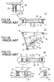
- FIGS. 1A, 1B and 1C show a conventional capstan tilt adjustment mechanism 10 in a magnetic tape recording/reproducing apparatus.
- Reference numeral 11 is the capstan
- 12 is the pinch roller
- 13 is a capstan motor
- 14 is a capstan motor support plate
- 15 is a chassis.
- the capstan 11 itself forms the spindle of the capstan motor 13.
- the capstan motor 13 is mounted on a bottom surface of the capstan motor support plate 14, with the capstan 11 protruding upward through the capstan motor support plate 14.
- the capstan motor support plate 14 is fixedly mounted on the chassis 15 at three separate locations indicated in the drawings as A, B and C.
- the pinch roller 12 is pressed against the capstan 11 in the direction of the arrow D, sandwiching the magnetic tape 16 therebetween.
- the magnetic tape 16 runs forward in the direction of arrow F.
- the magnetic tape 16 runs backward in the direction of arrow R.
- the direction in which the tilt of the capstan 11 should be adjusted is indicated by the arrows G1 and G2.
- Mounting position A comprises the capstan motor support plate 14 set on a top edge of a post 20 formed on the chassis 15, with a screw 21 screwed into the post 20 so as to fixedly mount the capstan motor support plate 14 in place.
- Mounting position B comprises a coil spring 23 fitted around a periphery of a post 22 formed on a top of the chassis 15, a hole 14a of the capstan motor support plate 14 fitted to the post 22, and a screw 24 screwed into the post 22 from a top edge of the post 22.
- the capstan motor support plate 14 is lifted upward by the coil spring 23 against a bottom surface of a head portion of the screw 24.
- Mounting position C comprises a coil spring 26 fitted around a bolt 25 formed on the chassis 15, a hole of the capstan motor support plate 14 fitted to the bolt 25, and a nut 27 fastened to the bolt 25.
- the capstan motor support plate 14 is lifted upward by the coil spring 26 and pressed against a bottom surface of a head portion of the nut 27.
- Line H is a line connecting mounting position A and mounting position B.
- Line I is a line passing through mounting location C and intersecting with line H.
- Tightening the nut 27 causes mounting location C of the capstan motor support plate 14 to sink, the capstan motor support plate 14 to tilt about the line H and an edge of the capstan 11 to tilt toward mounting position C parallel to line I. Conversely, loosening the nut 27 causes mounting location C of the capstan motor support plate 14 to rise and the capstan 11 to tilt away from mounting position C parallel to line I. In this manner the tilt of the capstan 11 is adjusted and the reverse run of the magnetic tape made the same as the forward run of the magnetic tape.
- the direction of the tilt of the capstan 11 may in some cases be changed by the force of the coil spring 23 because mounting location B supports the capstan motor support plate 14 by using a coil spring 23. If the force of the coil spring 23 is weak, then the capstan 11 will tilt in the direction shown in arrow J when the nut 27 is manipulated, and consequently the tilt of capstan 11 will deviate from the proper adjustment direction by an angle ⁇ . As a result, it can become difficult to make the reverse run of the tape the same as the forward run of the tape.
- capstan motor support plate 14 is susceptible to external vibrations because mounting location B supports the capstan motor support plate 14 by using a coil spring 23.
- the first and second supporting parts have a structure that restricts movement of the support plate in the vertical direction, so the tilt of the capstan can be adjusted smoothly in the proper adjustment direction because the support plate does not tilt along the direction of the first and second supporting parts. Accordingly, it is possible to make the magnetic tape behave the same way when run in reverse as when the magnetic tape is run forward.
- the first and second supporting parts have a structure that restricts movement of the support plate in the vertical direction, so vibration of the capstan motor support plate is not amplified in the event that external vibrations are received and the capstan and an area thereabout acquire a vibration resistance superior to that of the conventional art.
- the first and second supporting parts each comprise:
- restrictive force exerted by the capstan motor support plate on the first and second supporting parts during its adjustment is small, so the pivotal displacement clockwise and counter-clockwise of the capstan motor support plate through the range of the small angle centered on line K does not unnecessarily bend the capstan motor support plate and, accordingly, the width of the air gap does not change. As a result, the characteristics of the capstan motor are not affected.
- FIG. 2 is a diagram showing a plan view of an embodiment of a DAT streamer 50 as the magnetic tape recording/reproducing apparatus according to the present invention.
- Magnetic tape 52 is extracted from a loaded DAT tape cassette 51 by loading poles 53 and 54, wound around a rotary drum 55 having rotary heads 55a and a pinch roller 56 is pressed against a capstan 57 from a direction indicated in the drawing by arrow N.
- the magnetic tape 52 When the capstan 57 is rotated by a capstan motor 58 in a counter-clockwise direction, the magnetic tape 52 is guided by poles 59a and 59b located on both sides of the capstan 57, the magnetic tape 52 is run in a forward direction indicated by the arrow F and data is either recorded on the magnetic tape 52 by the rotary head or the rotary head reproduces data recorded on the magnetic tape 52.
- the capstan motor 58 reverses and the capstan 57 is rotated in a clockwise direction, the magnetic tape 52 is run in a reverse direction indicated in the drawing by arrow R.
- the recording of data on the magnetic tape 52 is accomplished by reproducing the recorded location to verify that the data has been recorded. As a result, the capstan repeatedly rotates in counter-clockwise and clockwise directions and the magnetic tape 52 repeatedly runs in forward and reverse directions.
- the capstan motor 58 has a stator coil 61, a rotor magnet 60, a capstan 57 that is fixedly mounted on and vertically penetrates the rotor magnet 60, a capstan motor support plate 63 and a capstan housing 64.
- the stator coil 61 is attached to a lower surface of the capstan motor support plate 63.
- the capstan 57 is supported at both a top and a base portion by bearings 64a within the capstan housing 64.
- the capstan motor support plate 63 is caulked and fixedly mounted on a lower surface of a flange part 64b of the capstan housing 64.
- the rotor magnet 60 is disposed opposite the stator coil 61 across an air gap 65 interposed therebetween.
- the capstan motor support plate 63 is mounted on an upper surface of the chassis 62 in a manner to be described later.
- the rotor magnet 60 is accommodated within an opening 62a in the chassis 62.
- the sub-chassis 66 is mounted on the upper surface of the chassis 62 so as to cover the capstan motor support plate 63.
- FIG. 3A the direction in which the tilt of the capstan 57 should be adjusted in order to make the magnetic tape behave when running in reverse the same way it behaves when running forward is indicated by arrows J1 and J2.
- Arrows J1 and J2 indicate a direction identical to the direction in which the magnetic tape 52 runs in the vicinity of the capstan 57.
- the DAT streamer 50 has a capstan tilt adjustment mechanism 70.
- the capstan tilt adjustment mechanism 70 has first and second supporting parts 71 and 72 that both support and at the same time fixedly mount the capstan motor support plate 63 at two locations, as well as an adjusting screw mechanism 73 at one location that moves vertically with respect to the surface of the capstan motor support plate 63.
- the first and second supporting parts 71 and 72 are aligned along a line K that passes through the center of the capstan 57 and runs perpendicular to the direction indicated by arrows J1, J2 and are positioned symmetrically at positions P1 and P2 on both sides of the capstan 57.
- line K is the same as the direction indicated by arrow N, which is the direction in which the pinch roller 56 presses against the capstan 57.
- the adjusting screw mechanism 73 lies on a line M that passes through the center of the capstan 57 and intersects perpendicular to the above-described line K, and is positioned at a position P3 at a distance L1 from the capstan in the direction indicated by arrow J2. This distance L1 is approximately 30 mm, which is long. Holes 63a, 63b and 63c are formed on the capstan motor support plate 63 at locations corresponding to above-mentioned locations P1, P2 and P3.
- First and second supporting parts 71 and 72 have the same structure and resemble a fulcrum. As shown in FIG. 3B and FIG. 4 , reference numerals 74 and 75 are the base portions of the fulcrum and project upward from the chassis 62 with which they form a single integrated unit, having a longer wedge-shaped axis in the direction of the line K.
- the supporting surfaces 74a and 75a at the apexes of the base portions 74 and 75 have a width W1 of only approximately 1 mm in a direction perpendicular to the direction of line K.
- the first and second supporting parts 71 and 72 have a rigidity sufficient to prevent movement of the capstan motor support plate 63 in a vertical direction with respect to the surface of the capstan motor support plate 63.
- vertical screw holes 74b and 75b are formed in each of the base portions 74 and 75 of the fulcrum.
- Reference numerals 76 and 77 are countersunk screws, with head portions 76a and 77a having a shape like that of an inverted cone.
- the countersunk screws 76 and 77 are passed through the holes 63a and 63b formed in the capstan motor support plate 63 and are screwed into the screw holes 74b and 75b, the capstan motor support plate 63 resting on top of the supporting surfaces 74a and 75a of the apexes of the base portions 74 and 75 of the fulcrum and supported by and fixedly mounted thereto.
- the supporting surfaces 74a and 75a at the apexes of the base portions 74 and 75 of the fulcrum have a narrow width W1 of approximately 1 mm in a direction perpendicular to line K.
- the portions where the head portions 76a and 77a of the countersunk screws 76 and 77 press down upon the capstan motor support plate are restricted to only the edges 63a1 and 63b1 of the holes 63a and 63b, such that the upper surface of the capstan motor support plate 63 in the periphery of the holes 63a and 63b is not suppressed.
- the restrictive force exerted on the first and second supporting parts 71 and 72 by the capstan motor support plate 63 during its swinging displacement is small.
- the swinging displacement clockwise and counter-clockwise of the capstan motor support plate 63 through the range of the small angle centered on line K does not bend the capstan motor support plate 63.
- the support surface 75a of the second supporting part 72 and the head portion 76a of the countersunk screw 76 receive the force of the pinch roller 56 pressing against the capstan 57.
- the adjusting screw mechanism 73 comprises a bolt 80 that is vertically mounted on the chassis 62, a compression coil spring 81 fitted around the bolt 80, the lower surface of the capstan motor support plate 63 around the periphery of the hole 63a formed in the capstan motor support plate 63 resting on a top edge of the compression coil spring 81, and a screw 82 engaging that portion of the bolt 80 that projects upward from the hole 63c.
- Tightening the screw 82 causes the position P3 of the capstan motor support plate 63 to sink and loosening the screw 82 causes the position P3 of the capstan motor support plate 63 to rise.
- the capstan motor support plate 63 is supported and fixedly mounted atop the supporting surfaces 74a and 75a at the apexes of the first and second supporting parts 71 and 72, so that even with the exertion of the force of the pinch roller 56 pressing against the capstan 57 the capstan motor support plate 63 does not sink at positions P1 and P2 but is maintained at a predetermined level. Accordingly, the capstan motor support plate 63 does not tilt toward the P2 position side but swings and tilts about line K. The tip of the capstan 57 is not displaced in the direction of line K but is instead displaced along line M either toward or away from position P3.
- the tilt of the capstan 57 is always adjusted so that the tip of the capstan is displaced either in the direction indicated by arrow J1 or the direction indicated by arrow J2. Accordingly, the magnetic tape is definitely adjusted so as to behave the same way when run in reverse as it does when run forward.
- the restrictive force exerted by the capstan motor support plate 63 on the first and second supporting parts 71 and 72 is small, so the swinging displacement clockwise and counter-clockwise of the capstan motor support plate 63 through the range of the small angle centered on line K does not bend the capstan motor support plate 63 and, accordingly, the width of the air gap 65 does not change. As a result, the characteristics of the capstan motor 58 are not affected.
- the above-described distance L1 is approximately 30 mm, which is long.
- the angle of deflection of the capstan 57 is small in relation to any given angle of rotation of the screw 82, so it is possible to make fine adjustments to the angle of the capstan 57.
- first and second supporting parts 71 and 72 both have rigid structures, so vibration of the capstan motor support plate 63 is not amplified in the event that external vibrations are received and the capstan 57 and the area thereabout acquire a vibration resistance superior to that of the conventional art.
- FIGS. 5A, 5B , 6 and 7 This embodiment is claimed in a divisional application, published as EP-A-1 117 097 .
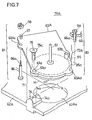
- This capstan tilt adjustment mechanism 70A uses the same supporting member 71 as the capstan tilt adjustment mechanism 70 described above but the second supporting member 72A is not fixedly mounted by a screw. Moreover, an adjusting screw mechanism 90 and a spring-loaded pushing mechanism 91 have replaced the adjusting screw mechanism 73. Otherwise, the structural parts in FIGS. 5A, 5B , 6 and 7 that are the same as the structural parts in FIGS. 3A, 3B and 4 are given the same reference numerals, and the structural parts that are not the same but which correspond are given the same reference numerals but with the letter "A" added.
- a second supporting part 72A comprises a supporting pin 95 fixedly mounted at a location of a hole 63b in a capstan motor support plate 63A.
- the supporting pin 95 protrudes downward and a rounded portion 95a at the bottom tip of the supporting pin 95 contacts an upper surface of the capstan motor support plate 63A.
- the pressing force of the pinch roller 56 is exerted downward on the supporting pin 95 and the supporting pin 95 is pressed by the upper surface of the chassis 62A.
- the first supporting part 71 and of course the second supporting part 72A as well have a rigidity which prevents the capstan motor support plate 63 from moving in a direction downward from and perpendicular to the surface of the capstan motor support plate 63.
- the spring-loaded pushing mechanism 91 is provided at the location of the adjusting screw mechanism 73 shown in FIG. 4 .
- a guide pole 96 having a bolt 96a at a tip portion thereof is fixedly mounted perpendicular to the chassis 62, a hole 63Ac in the capstan motor support plate 63A engages the guide pole 96, a compression coil spring 97 engages that portion of the guide pole 96 which protrudes above the hole 63Ac and rests atop the capstan motor support plate 63A.
- a screw 98 engages the bolt 96a, the compression coil spring 97 is compressed between the screw 98 and the capstan motor support plate 63A and the capstan motor support plate 63A is pressed downward.
- the adjusting screw mechanism 90 is atop line M and is provided at a portion opposite the spring-loaded pushing mechanism 91 with respect to the capstan 57.
- This adjusting screw mechanism 90 comprises a bolt-like adjusting screw 99 that engages a screw hole 66a in a sub-chassis 66 and which projects below a bottom of the sub-chassis, the bottom tip of the which presses on a portion 63Ad of the capstan motor support plate 63A.
- the capstan motor support plate 63A swings and tilts about line K, the tilt is adjusted so that the tip of the capstan 57 is deflected in either the direction of arrow J2 or the direction of arrow J1 and the magnetic tape behaves the same when run in reverse as it does when run forward.
- the second supporting part 72A of this capstan tilt adjustment mechanism 70A is not fixedly mounted in place by a screw, so the restrictive force exerted on the capstan motor support plate 63A is weak as compared to that of the capstan tilt adjustment mechanism 70 described above. Accordingly, the capstan motor support plate 63A is tilted more smoothly than with the capstan tilt adjustment mechanism 70 described above, and the tilt adjustment of the capstan 57 is performed more smoothly.
- capstan tilt adjustment mechanism 70B is the same as the capstan tilt adjustment mechanism 70A.described above except for the second supporting part 72A, which is replaced with a second supporting part 72B.
- the second supporting part 72B has a structure that is the reverse of the structure of the second supporting part 72A shown in FIG. 7 . That is, a supporting pin 100 is fixedly mounted on and projects upwardly from a chassis 62B. A rounded part 100a of an upper tip of the supporting pin 100 contacts a lower surface of a projecting portion 63Be of a capstan motor support plate 63B. The supporting pin 100 receives the pressing force of the pinch roller 56.
- the tilt is adjusted so that the tip of the capstan 57 is deflected in either the direction of arrow J2 or the direction of arrow J1 and the magnetic tape behaves the same when run in reverse as it does when run forward.
- the second supporting part 72B of this capstan tilt adjustment mechanism 70B is not fixedly mounted in place by a screw, so the restrictive force exerted on the capstan motor support plate 63B is weak as compared to that of the capstan tilt adjustment mechanism 70 described above. Accordingly, the capstan motor support plate 63B is tilted smoothly with even less bending than with the capstan tilt adjustment mechanism 70 described above, and the tilt adjustment of the capstan 57 is performed more smoothly.
Landscapes
- Engineering & Computer Science (AREA)
- Power Engineering (AREA)
- Adjustment Of The Magnetic Head Position Track Following On Tapes (AREA)
Claims (4)
- Appareil d'enregistrement/reproduction à bande magnétique (50) comportant:un galet presseur (56);un cabestan d'entraînement (57) contre lequel le galet presseur (56) presse de manière à entraîner une bande magnétique (52); etun mécanisme de réglage d'inclinaison de cabestan d'entraînement (70) pour régler l'inclinaison du cabestan d'entraînement (57);le mécanisme de réglage d'inclinaison de cabestan d'entraînement (70) comprenant:une plaque support (63) pour supporter le cabestan d'entraînement mobile en rotation;une première partie de support (71) et une seconde partie de support (72) pour supporter la plaque support (63) de manière pivotante à une hauteur prédéterminée par rapport à un châssis (62) à des positions des deux côtés du cabestan d'entraînement (57) de manière à incliner le cabestan d'entraînement (57) dans une direction afin de permettre à la bande magnétique (52) de défiler de manière sensiblement régulière et sans endommagement des bords de la bande; etun mécanisme à vis de réglage (73) pour pivoter la plaque support (63) par rapport au châssis (62); caractérisé en ce queles première et seconde parties de support (71, 72) comprennent chacune un élément de support sensiblement en forme de coin (74, 75) formé sur le châssis et sensiblement rigide pour empêcher tout déplacement de la plaque support dans une direction verticale.
- Appareil d'enregistrement/reproduction à bande magnétique (50) selon la revendication 1, dans lequel les première et seconde parties de support (71, 72) comprennent chacune:une vis (76, 77) qui traverse un trou (63a, 63b) dans la plaque support (63) et se visse dans un trou (74b, 75b) dans l'élément de support respectif (74, 75) et qui monte la plaque support (63) sur l'élément de support (74, 75).
- Appareil d'enregistrement/reproduction à bande magnétique (50) selon la revendication 2, dans lequel la vis est une vis à tête fraisée plate.
- Appareil d'enregistrement/reproduction à bande magnétique (50) selon l'une quelconque des revendications 1 à 3, dans lequel les première et seconde parties de support (71, 72) sont disposées le long d'une ligne qui traverse le cabestan d'entraînement (57) et qui se trouve en outre dans une direction dans laquelle le galet presseur (56) est pressé contre le cabestan d'entraînement (57).
Priority Applications (1)
| Application Number | Priority Date | Filing Date | Title |
|---|---|---|---|
| EP01109127A EP1117097A3 (fr) | 1998-12-21 | 1999-12-21 | Appareil d'enregistrement / de reproduction de bande magnétique |
Applications Claiming Priority (2)
| Application Number | Priority Date | Filing Date | Title |
|---|---|---|---|
| JP10362954A JP2000187906A (ja) | 1998-12-21 | 1998-12-21 | 磁気テープ記録再生装置 |
| JP36295498 | 1998-12-21 |
Related Child Applications (1)
| Application Number | Title | Priority Date | Filing Date |
|---|---|---|---|
| EP01109127A Division EP1117097A3 (fr) | 1998-12-21 | 1999-12-21 | Appareil d'enregistrement / de reproduction de bande magnétique |
Publications (2)
| Publication Number | Publication Date |
|---|---|
| EP1014356A1 EP1014356A1 (fr) | 2000-06-28 |
| EP1014356B1 true EP1014356B1 (fr) | 2008-10-29 |
Family
ID=18478156
Family Applications (2)
| Application Number | Title | Priority Date | Filing Date |
|---|---|---|---|
| EP01109127A Withdrawn EP1117097A3 (fr) | 1998-12-21 | 1999-12-21 | Appareil d'enregistrement / de reproduction de bande magnétique |
| EP99310342A Expired - Lifetime EP1014356B1 (fr) | 1998-12-21 | 1999-12-21 | Appareil d'enregistrement / de reproduction de bande magnétique |
Family Applications Before (1)
| Application Number | Title | Priority Date | Filing Date |
|---|---|---|---|
| EP01109127A Withdrawn EP1117097A3 (fr) | 1998-12-21 | 1999-12-21 | Appareil d'enregistrement / de reproduction de bande magnétique |
Country Status (4)
| Country | Link |
|---|---|
| US (1) | US6398095B1 (fr) |
| EP (2) | EP1117097A3 (fr) |
| JP (1) | JP2000187906A (fr) |
| DE (1) | DE69939806D1 (fr) |
Families Citing this family (6)
| Publication number | Priority date | Publication date | Assignee | Title |
|---|---|---|---|---|
| JP4161759B2 (ja) * | 2003-03-19 | 2008-10-08 | 松下電器産業株式会社 | 磁気記録再生装置 |
| KR100582897B1 (ko) * | 2004-07-26 | 2006-05-25 | 삼성전자주식회사 | 테이프 기록/재생장치 |
| US7301724B2 (en) * | 2004-09-08 | 2007-11-27 | Hewlett-Packard Development Company, L.P. | Transducing head |
| US7961430B2 (en) * | 2006-09-19 | 2011-06-14 | International Business Machines Corporation | Tape path control system with precision-aligned conjugated rollers |
| DE102011106998B4 (de) * | 2011-06-29 | 2014-07-17 | STEMPLINGER Gesellschaft für Konstruktion, Verzahnungs- und Fertigungstechnik mbH | Montagevorrichtung sowie Maschinenanordnung mit einer solchen Montagevorrichtung |
| CN105337444A (zh) * | 2015-09-25 | 2016-02-17 | 中国航空工业集团公司沈阳发动机设计研究所 | 一种双向调节底座 |
Family Cites Families (7)
| Publication number | Priority date | Publication date | Assignee | Title |
|---|---|---|---|---|
| DE1140737B (de) | 1961-12-15 | 1962-12-06 | Grundig Max | Vorrichtung zur kontinuierlichen Einstellung einer Tonwelle bei Magnettonbandgeraeten |
| US4085906A (en) | 1976-12-13 | 1978-04-25 | Three Phoenix Company | Magnetic tape cartridge transport |
| AT356410B (de) | 1978-06-09 | 1980-04-25 | Philips Nv | Aufzeichnungs- und/oder wiedergabegeraet |
| JPS622924Y2 (fr) | 1981-06-10 | 1987-01-23 | ||
| US4562946A (en) | 1982-09-16 | 1986-01-07 | Ampex Corporation | Tape transport |
| US5901011A (en) * | 1995-08-24 | 1999-05-04 | Lg Electronics Inc. | Tape guide angle controlling apparatus for magnetic tape recorder-player |
| JP3351371B2 (ja) * | 1998-03-19 | 2002-11-25 | 松下電器産業株式会社 | 磁気記録再生装置 |
-
1998
- 1998-12-21 JP JP10362954A patent/JP2000187906A/ja active Pending
-
1999
- 1999-12-10 US US09/459,188 patent/US6398095B1/en not_active Expired - Fee Related
- 1999-12-21 DE DE69939806T patent/DE69939806D1/de not_active Expired - Fee Related
- 1999-12-21 EP EP01109127A patent/EP1117097A3/fr not_active Withdrawn
- 1999-12-21 EP EP99310342A patent/EP1014356B1/fr not_active Expired - Lifetime
Also Published As
| Publication number | Publication date |
|---|---|
| JP2000187906A (ja) | 2000-07-04 |
| DE69939806D1 (de) | 2008-12-11 |
| EP1117097A2 (fr) | 2001-07-18 |
| EP1117097A3 (fr) | 2003-03-12 |
| US6398095B1 (en) | 2002-06-04 |
| EP1014356A1 (fr) | 2000-06-28 |
Similar Documents
| Publication | Publication Date | Title |
|---|---|---|
| US5610782A (en) | Floppy disk drive device | |
| US7450345B2 (en) | Magnetic head supporting mechanism with two openings proximate to pivot of load beam | |
| JP3797997B2 (ja) | ボイスコイルモータ連結構造 | |
| JPH06251517A (ja) | 磁気ディスク装置 | |
| EP1117097A2 (fr) | Appareil d'enregistrement / de reproduction de bande magnétique | |
| US6369963B1 (en) | Optical pickup apparatus | |
| US7245456B2 (en) | Head support device and disk drive using the same | |
| JPH0520748A (ja) | 磁気記録再生装置の回転ヘツドドラム装置 | |
| CA1246737A (fr) | Appareil d'enregistrement et/ou de lecture a cassette de bande magnetique | |
| JP3405652B2 (ja) | ディスク再生装置 | |
| US20030038561A1 (en) | Motor for use with thin type inner rotor and disk apparatus | |
| WO2005013269A1 (fr) | Dispositif d'enregistrement/reproduction a disque et procede pour fixer un capteur du dispositif d'enregistrement/reproduction a disque | |
| US5703737A (en) | Magnetic recording reproduction apparatus with improved adjustment characteristics for audio-control head | |
| JPS5958669A (ja) | 回転型ヘツドアクセス装置 | |
| JPH0718053Y2 (ja) | ヘッド支持装置 | |
| JP2604178Y2 (ja) | 複数のテープガイドを備えた回転磁気ヘッド | |
| JP2819997B2 (ja) | テープガイド装置 | |
| KR200154855Y1 (ko) | 브이씨알의 오디오/콘트롤 헤드 스프링장력 조절장치 | |
| JP3006793U (ja) | ビデオカセットレコーダーのオーディオヘッドの位置調節装置 | |
| JP2000187907A (ja) | 磁気テープ記録再生装置 | |
| JPH073454Y2 (ja) | 磁気ヘツド調整機構 | |
| EP0905682A1 (fr) | Mécanisme de support de tête magnétique. | |
| KR19980023820A (ko) | 브이씨알의 오디오/콘트롤 헤드 취부구조 | |
| JPS60160063A (ja) | フロツピ−デイスク装置のヘツド支持機構 | |
| JP2004171757A (ja) | 磁気ディスク装置 |
Legal Events
| Date | Code | Title | Description |
|---|---|---|---|
| PUAI | Public reference made under article 153(3) epc to a published international application that has entered the european phase |
Free format text: ORIGINAL CODE: 0009012 |
|
| AK | Designated contracting states |
Kind code of ref document: A1 Designated state(s): DE FR GB |
|
| AX | Request for extension of the european patent |
Free format text: AL;LT;LV;MK;RO;SI |
|
| 17P | Request for examination filed |
Effective date: 20001227 |
|
| AKX | Designation fees paid |
Free format text: DE FR GB |
|
| RAP1 | Party data changed (applicant data changed or rights of an application transferred) |
Owner name: HEWLETT-PACKARD COMPANY, A DELAWARE CORPORATION Owner name: MITSUMI ELECTRIC CO., LTD. |
|
| GRAP | Despatch of communication of intention to grant a patent |
Free format text: ORIGINAL CODE: EPIDOSNIGR1 |
|
| GRAS | Grant fee paid |
Free format text: ORIGINAL CODE: EPIDOSNIGR3 |
|
| GRAA | (expected) grant |
Free format text: ORIGINAL CODE: 0009210 |
|
| AK | Designated contracting states |
Kind code of ref document: B1 Designated state(s): DE FR GB |
|
| REG | Reference to a national code |
Ref country code: GB Ref legal event code: FG4D |
|
| REF | Corresponds to: |
Ref document number: 69939806 Country of ref document: DE Date of ref document: 20081211 Kind code of ref document: P |
|
| PLBE | No opposition filed within time limit |
Free format text: ORIGINAL CODE: 0009261 |
|
| STAA | Information on the status of an ep patent application or granted ep patent |
Free format text: STATUS: NO OPPOSITION FILED WITHIN TIME LIMIT |
|
| REG | Reference to a national code |
Ref country code: FR Ref legal event code: ST Effective date: 20090831 |
|
| 26N | No opposition filed |
Effective date: 20090730 |
|
| PG25 | Lapsed in a contracting state [announced via postgrant information from national office to epo] |
Ref country code: DE Free format text: LAPSE BECAUSE OF NON-PAYMENT OF DUE FEES Effective date: 20090701 |
|
| PG25 | Lapsed in a contracting state [announced via postgrant information from national office to epo] |
Ref country code: FR Free format text: LAPSE BECAUSE OF NON-PAYMENT OF DUE FEES Effective date: 20081231 |
|
| PGFP | Annual fee paid to national office [announced via postgrant information from national office to epo] |
Ref country code: GB Payment date: 20091216 Year of fee payment: 11 |
|
| GBPC | Gb: european patent ceased through non-payment of renewal fee |
Effective date: 20101221 |
|
| PG25 | Lapsed in a contracting state [announced via postgrant information from national office to epo] |
Ref country code: GB Free format text: LAPSE BECAUSE OF NON-PAYMENT OF DUE FEES Effective date: 20101221 |