EP1014523A1 - Boíte d'encastrement, notamment pour cloison sèche - Google Patents
Boíte d'encastrement, notamment pour cloison sèche Download PDFInfo
- Publication number
- EP1014523A1 EP1014523A1 EP99402965A EP99402965A EP1014523A1 EP 1014523 A1 EP1014523 A1 EP 1014523A1 EP 99402965 A EP99402965 A EP 99402965A EP 99402965 A EP99402965 A EP 99402965A EP 1014523 A1 EP1014523 A1 EP 1014523A1
- Authority
- EP
- European Patent Office
- Prior art keywords
- housing
- box according
- sleeve
- installation box
- web
- Prior art date
- Legal status (The legal status is an assumption and is not a legal conclusion. Google has not performed a legal analysis and makes no representation as to the accuracy of the status listed.)
- Granted
Links
- 238000009434 installation Methods 0.000 claims description 32
- 239000012774 insulation material Substances 0.000 claims description 20
- 238000004891 communication Methods 0.000 claims description 7
- 210000000078 claw Anatomy 0.000 claims description 6
- 239000000463 material Substances 0.000 abstract description 9
- 238000002955 isolation Methods 0.000 abstract description 2
- 230000008901 benefit Effects 0.000 description 9
- 238000009413 insulation Methods 0.000 description 4
- 238000002513 implantation Methods 0.000 description 3
- 238000005192 partition Methods 0.000 description 3
- 238000004873 anchoring Methods 0.000 description 2
- 239000004020 conductor Substances 0.000 description 2
- 229940082150 encore Drugs 0.000 description 2
- 239000011505 plaster Substances 0.000 description 2
- 206010061876 Obstruction Diseases 0.000 description 1
- 239000011324 bead Substances 0.000 description 1
- 230000015572 biosynthetic process Effects 0.000 description 1
- 239000000470 constituent Substances 0.000 description 1
- 230000000694 effects Effects 0.000 description 1
- 239000006260 foam Substances 0.000 description 1
- 230000014759 maintenance of location Effects 0.000 description 1
- 238000000465 moulding Methods 0.000 description 1
- 238000012856 packing Methods 0.000 description 1
- 230000001737 promoting effect Effects 0.000 description 1
- 238000007789 sealing Methods 0.000 description 1
- 238000006467 substitution reaction Methods 0.000 description 1
- 210000002105 tongue Anatomy 0.000 description 1
- 230000003313 weakening effect Effects 0.000 description 1
Images


Classifications
-
- H—ELECTRICITY
- H02—GENERATION; CONVERSION OR DISTRIBUTION OF ELECTRIC POWER
- H02G—INSTALLATION OF ELECTRIC CABLES OR LINES, OR OF COMBINED OPTICAL AND ELECTRIC CABLES OR LINES
- H02G3/00—Installations of electric cables or lines or protective tubing therefor in or on buildings, equivalent structures or vehicles
- H02G3/02—Details
- H02G3/08—Distribution boxes; Connection or junction boxes
- H02G3/12—Distribution boxes; Connection or junction boxes for flush mounting
- H02G3/123—Distribution boxes; Connection or junction boxes for flush mounting in thin walls
-
- H—ELECTRICITY
- H02—GENERATION; CONVERSION OR DISTRIBUTION OF ELECTRIC POWER
- H02G—INSTALLATION OF ELECTRIC CABLES OR LINES, OR OF COMBINED OPTICAL AND ELECTRIC CABLES OR LINES
- H02G3/00—Installations of electric cables or lines or protective tubing therefor in or on buildings, equivalent structures or vehicles
- H02G3/02—Details
- H02G3/08—Distribution boxes; Connection or junction boxes
- H02G3/088—Dustproof, splashproof, drip-proof, waterproof, or flameproof casings or inlets
Definitions
- the present invention relates generally to boxes type of those used for the installation of a any apparatus, and in particular any apparatus electric, even within a partition.
- this partition is a drywall.
- a drywall is a partition which, formed, the most often, prefabricated elements suitably assembled, present, internally, voids or is likely to be easily hollowed out, while comprising, on the front, a continuous facing, consisting, for example, of plasterboard duly jointed.
- Facing depends on certain characteristics, and, in particular, the fire performance and sound and / or thermal insulation.
- the proposed installation box includes a housing, which, having a side wall and a bottom, forms an open housing forward and is thus suitable for the installation of any device, and a sleeve, which surrounds the casing, at a distance from it, and which, in practical, extends beyond the bottom of this case.
- German utility model No 78 23 347 the sleeve belongs to a second box in which the first must be engaged, and the space, unique, formed between this case and the first, opens naturally forward.
- the material of insulation used is an expandable material, that is to say a material which, initially presented in a more or less compact form, is likely to expand, in this case under the action of fire, thereby generating a kind of foam.
- the lining of the space, unique, formed between the housing, the sleeve and the veil is easy, since, already preexisting, this space does not imply not, for its creation, any relative movement between the elements which delimit it.
- this space can advantageously be completely filled from the origin, and the insulation material used for this filling can then advantageously be plaster, as the constituent material of facing concerned, for the benefit of a more rigorous reconstruction of the continuity of its characteristics.
- the space to be filled therefore opens towards the rear.
- the present invention generally relates to a provision to avoid this drawback.
- a recessed box of the type comprising a housing, which, having a side wall and a bottom, forms a housing open towards the front, a sleeve, which surrounds the housing, distance from it, extending beyond the bottom of this case, and a veil, which, extending generally transversely with respect to the assembly, secures the sleeve to the housing,
- this mounting box being of a generally characterized in that the housing, the sleeve and the veil jointly define two distinct spaces, which act on both sides and on the other side of the veil, and each of which is likely to be used to the implantation of any insulation material, namely, a front space accessible from the front, and a rear space accessible from the rear, and in that these two spaces are in communication with each other.
- the veil ensuring the attachment of the sleeve to the housing is perforated by at least one recess, and, preferably, of several recesses which intervene from place in place along its surface.
- this insulation material when placing this insulation material in the front space, it acts like a vent and an overflow, which allows a particularly efficient filling of this front space.
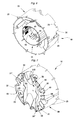
- this mounting box 10 comprises, overall, a housing 15, which, intended to receive the apparatus concerned, forms a housing 16 open towards the front, presenting, to do this, a side wall 18 and a bottom 19, a sleeve 20, which surrounds the housing 15, at distance from it, and, more precisely, from its side wall 18, in extending beyond the bottom 19 of this housing 15 relative to its outlet, and a web 21, which, extending generally transversely relative to the assembly, over at least part of the periphery of the sleeve 20, secures this sleeve 20 to housing 15.
- the housing 15 has, in plan, a generally circular outline, and it is the same of sleeve 20.
- the side wall 18 of the housing 15 is generally cylindrical.
- this side wall 18 forms, locally, in diametrically opposite positions relative to each other, two flats 22, in favor of each of which a screw 23 intervenes, for fixing the apparatus concerned when this fixing is done using such screws 23, and the internal surface of which has transverse grooves 24, in the case where this fixing is done using claws.
- the sleeve 20 is itself generally cylindrical.
- the sleeve 20 comprises, on the one hand, bosses 25, in the form of a wedge, which, distributed circularly all around its circumference, protrude from place in place on its outer surface, at the outlet of the housing 15, and, on the other hand, at least one recess 26, which recesses in hollow on its external surface, substantially following a generator, and thanks to which intervenes a claw 27 controlled by a screw 29.
- two claws 27 are provided, each controlled by a screw 29, and they operate in diametrically opposite positions, one relative to each other, to the right, each respectively, of the flats 22 of the side wall 18 of the housing 15.
- each recess 26 forms, at its base, that is to say on the side opposite the bosses 25, a recess 30, enlarged, for the initial retraction of the corresponding claw 27 in the outer contour overall of sleeve 20.
- the housing 15, the sleeve 20 and the web 21 jointly define two distinct spaces 31A, 31B, which intervene on either side of the veil 21, and each of which is likely to be profit for the implantation of any insulation material, according to arrangements described in more detail later, namely, between the wall side 18 of the housing 15 and the sleeve 20, a front space 31A accessible from the front, and, behind the bottom 19 of the housing 15, a rear space 31B accessible from the rear, and these two spaces 31A, 31B are in communication with each other.
- the web 21 is connected to the sleeve 20 set back from the free edge 32 of this sleeve 20, on a part, at least, of the periphery thereof, on the side opposite to the outlet of the box 15, for the benefit of the amplitude thus given to the rear space 31B.
- the sleeve 20 forms, at the periphery of the web 21, on at least part of the outline thereof, of the side opposite the outlet of the housing 15, a flange 33, which delimits for its part the rear space 31B, following the contour of the recess or recesses 26, and, more precisely, of the niche 30 formed by these recesses 26.
- the web 21 intervenes substantially in the vicinity of the bottom 19 of the housing 15.
- the web 21 extends to an intermediate level between the bottom 19 of the housing 15 and the free edge 32 corresponding to the sleeve 20, and, for its connection to this web 21, the side wall 18 of the housing 15 comprises, at least locally, according to provisions described in more detail later, an extension 35.
- the web 21 is, in the embodiments shown, perforated with at least minus a recess 36.
- the web 21 is perforated with several recesses 36, which intervene from place to place along its surface.
- these recesses 36 occur at a distance from the flange 33 formed by the sleeve 20, and these are circular contour bores.
- the web 21 forms, locally, for guiding a conduit, not shown, specific to the housing conductors necessary for serving the equipment concerned, at least a gutter 38, which extends from the sleeve 20 to the housing 15, and the concavity is turned towards the space before 31A.
- gutters 38 there are four gutters 38, two pairs of gutters arranged in parallel to each other, in contact with each other, in diametrically positioned opposite to each other, crosswise with the recesses 26.
- these gutters 38 locally interrupt the rim 33 formed by the sleeve 20, and they extend obliquely relative to at the bottom 19 of the housing 15.
- the gutters 38 each open at the outside by an opening 39, which affects this sleeve 20 and / or the veil 21.
- the gutters 38 each extend at right an opening 40 of this case 15, which affects its side wall 18 and / or its bottom 19, and which, as shown, is possibly obscured by means shutter 41 erasable.
- these sealing means 41 are constituted by a cover which, precut in the side wall 18 of the housing 15, is knockout.
- the gutters 38 intervene between two ribs 42, which each extend along a sleeve cord 20.
- these ribs 42 are level with the free edge 32 of the sleeve 20, and they are parallel to each other.
- the two ribs 42 each have at least one notch 43.
- notch 43 is provided, and it intervenes in the median zone of the ribs 42.
- this notch 43 has a triangular outline.
- the rear space 31B is, in the forms of shown, divided into three portions, namely, one portion median 31 ', in which the gutters 38 extend, and two portions side 31 ", on each of which the niche 30 of the recess 26 bites corresponding.
- the veil 21 is reduced to the gutters 38, and, therefore, it is devoid of any recess.
- the front space 31A is more or less partitioned by ribs 44 which extend radially by splitting at count from sleeve 20.
- the housing 15, the sleeve 20 and the web 21 are of a integral, forming, jointly, molding, a single piece.
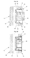
- conduits used to house the electrical conductors, extracted from the drywall 11, are introduced into the installation box 10 in favor of one and / or the other of its gutters 38, and a mass 45 of insulation material, for example plaster, is placed place in its rear space 31 B, until filling it, FIG. 5A.
- the box embedding 10 is engaged in the opening 14 of the drywall 11, up to come flush with the outer surface of the facing 12 concerned with this, as shown in Figure 5A.
- the bosses 25 of the sleeve 20 bite into the facing. 12, and, more specifically, in the portion thereof, which is sufficient to ensure anchoring, in one direction, the installation box 10 relative to this facing 12.
- the claws 27 are released from the niche 30 recesses 26 of the sleeve 20, and therefore projecting radially outwardly relative to it, they are brought into contact with the inner surface of the facing 12, which is sufficient to ensure the retention of the box embedding 10 with respect to this facing 12 in the opposite direction to the previous.
- a mass 46 of insulation material is to turn set up in the front space 31A of the installation box 10, until filling this space before 31A, as shown in Figure 5B.
- the housing 16 formed by the housing 15 can then be closed by a cover 48 until it is implemented.
- these recesses 36 are advantageously enlarged, which minimizes the risk that they may inadvertently become blocked during the placement of the mass 45 of insulation material, and this increases in advantageously also the contact surface of this mass 45 with the mass 46 present in the space before 31A, for the benefit of the cohesion of all.
- the sleeve 20 has, in correspondence, a notch 49 from its free edge 32.
- the notches 49 thus implemented promote evacuation of the insulation material towards the rim 33 of the sleeve 20 when fitting in place of the mass 45 of insulation material, for the benefit of a good spreading of the latter in this direction on the web 21.
- the veil 21 has studs 50 projecting from place to place, on its surface exterior, in the lateral portions 31 ", at least, of the rear space 31B, to perfect the anchoring of the mass 45 of insulation material.
- such pads 50 are only present than in the lateral portions 31 "of the rear space 31 B.
- these studs 50 have, in section transverse, a cruciform outline.
- the shutter means 41 associated with each opening 40 of the housing 15 are made up of elastically deformable tongues 51.
- the mounting box 10 according to the invention has, in a manner known per se, a oblong outline.
Landscapes
- Engineering & Computer Science (AREA)
- Architecture (AREA)
- Civil Engineering (AREA)
- Structural Engineering (AREA)
- Connection Or Junction Boxes (AREA)
- Sampling And Sample Adjustment (AREA)
Abstract
Description
Claims (21)
- Boíte d'encastrement du genre comportant un boítier (15), qui, présentant une paroi latérale (18) et un fond (19), forme un logement (16) ouvert vers l'avant, un manchon (20), qui entoure le boítier (15), à distance de celui-ci, en s'étendant au-delà du fond (19) de ce boítier (15), et un voile (21), qui, s'étendant globalement transversalement par rapport à l'ensemble, solidarise le manchon (20) au boítier (15), caractérisée en ce que le boítier (15), le manchon (20) et le voile (21) définissent, conjointement, deux espaces (31A, 31B) distincts, qui interviennent de part et d'autre du voile (21), et dont chacun est susceptible d'être mis à profit pour l'implantation d'un quelconque matériau d'isolation, à savoir, un espace avant (31 A) accessible de l'avant, et un espace arrière (31B) accessible de l'arrière, et en ce que ces deux espaces (31A, 31B) sont en communication l'un avec l'autre.
- Boíte d'encastrement suivant la revendication 1, caractérisée en ce que, pour l'établissement d'une communication entre les deux espaces (31A, 31B), le voile (21) est ajouré d'au moins un évidement (36).
- Boíte d'encastrement suivant la revendication 2, caractérisée en ce que le voile (21) est ajouré de plusieurs évidements (36), qui interviennent de place en place.
- Boíte d'encastrement suivant la revendication 3, caractérisée en ce que l'un au moins des évidements (36) du voile (21) intervient à la périphérie de celui-ci.
- Boíte d'encastrement suivant l'une quelconque des revendications 1 à 4, caractérisée en ce que le voile (21) se raccorde au manchon (20) en retrait par rapport au bord libre (32) de ce manchon (20), du côté opposé au débouché du boítier (15).
- Boíte d'encastrement suivant les revendications 4 et 5, prises conjointement, caractérisée en ce que, pour l'un au moins des évidements (36) du voile (21) qui interviennent à la périphérie de celui-ci, le manchon (20) présente, en correspondance, une échancrure (49) à compter de son bord libre (32).
- Boíte d'encastrement suivant l'une quelconque des revendications 1 à 6, caractérisée en ce que le voile (21) intervient au voisinage du fond (19) du boítier (15).
- Boíte d'encastrement suivant les revendications 5 et 7, prises conjointement, caractérisée en ce que le voile (21) s'étend à un niveau intermédiaire entre le fond (19) du boítier (15) et le bord libre (32) correspondant du manchon (20), et, pour son raccordement à ce voile (21), la paroi latérale (18) du boítier (15) comporte, au moins localement, un prolongement (35).
- Boíte d'encastrement suivant l'une quelconque des revendications 1 à 8, caractérisée en ce que le voile (21) forme, localement, au moins une gouttière (38) qui s'étend du manchon (20) au boítier (15).
- Boíte d'encastrement suivant la revendication 9, caractérisée en ce que, du côté du manchon (20), la gouttière (38) débouche à l'extérieur par un ajour (39) qui affecte ce manchon (20) et/ou le voile (21).
- Boíte d'encastrement suivant l'une quelconque des revendications 9, 10, caractérisée en ce que, du côté du boítier (15), la gouttière (38) s'étend au droit d'un ajour (40) de ce boítier (15), qui affecte sa paroi latérale (18) et/ou son fond (19), et qui est éventuellement occulté par des moyens d'obturation (41) effaçables.
- Boíte d'encastrement suivant l'une quelconque des revendications 9 à 11, caractérisée en ce que la gouttière (38) s'étend en oblique par rapport au fond (19) du boítier (15).
- Boíte d'encastrement suivant l'une quelconque des revendications 9 à 12, caractérisée en ce que la gouttière (38) intervient entre deux nervures (42), qui s'étendent chacune suivant une corde du manchon (20).
- Boíte d'encastrement suivant la revendication 13, caractérisée en ce que les deux nervures (42) sont à niveau avec le bord libre (32) du manchon (20).
- Boíte d'encastrement suivant l'une quelconque des revendications 12, 13, caractérisée en ce que les deux nervures (42) sont parallèles l'une à l'autre.
- Boíte d'encastrement suivant l'une quelconque des revendications 12 à 15, caractérisée en ce que les deux nervures (42) présentent, chacune, au moins une échancrure (43).
- Boíte d'encastrement suivant l'une quelconque des revendications 13 à 16, caractérisée en ce que, dans la portion médiane (31') de l'espace arrière (31B) comprise entre les deux nervures (42), le voile (21) est dépourvu de tout évidement.
- Boíte d'encastrement suivant l'une quelconque des revendications 9 à 17, caractérisée en ce qu'il y a quatre gouttières (38), à raison de deux paires de gouttières disposées parallèlement l'une à l'autre, en positions diamétralement opposées les unes par rapport aux autres.
- Boíte d'encastrement suivant l'une quelconque des revendications 1 à 18, caractérisée en ce que le voile (21) présente des plots (50) en saillie, de place en place, sur sa surface extérieure.
- Boíte d'encastrement suivant l'une quelconque des revendications 1 à 19, caractérisée en ce que le manchon (20) comporte au moins un renfoncement (26), à la faveur duquel intervient une griffe (27) commandée par une vis (29), et il forme, à la périphérie du voile (21), un rebord (33), qui délimite pour sa part l'espace arrière (31B), en suivant le contour du ou des renfoncements (26).
- Boíte d'encastrement suivant l'une quelconque des revendications 1 à 20, caractérisée en ce que le boítier (15), le manchon (20) et le voile (21) sont d'un seul tenant, en formant, conjointement, une seule et même pièce.
Applications Claiming Priority (2)
| Application Number | Priority Date | Filing Date | Title |
|---|---|---|---|
| FR9816191A FR2787644B1 (fr) | 1998-12-22 | 1998-12-22 | Boite d'encastrement, notamment pour cloison seche |
| FR9816191 | 1998-12-22 |
Publications (2)
| Publication Number | Publication Date |
|---|---|
| EP1014523A1 true EP1014523A1 (fr) | 2000-06-28 |
| EP1014523B1 EP1014523B1 (fr) | 2008-07-02 |
Family
ID=9534286
Family Applications (1)
| Application Number | Title | Priority Date | Filing Date |
|---|---|---|---|
| EP99402965A Expired - Lifetime EP1014523B1 (fr) | 1998-12-22 | 1999-11-29 | Boîte d'encastrement, notamment pour cloison sèche |
Country Status (6)
| Country | Link |
|---|---|
| EP (1) | EP1014523B1 (fr) |
| AR (1) | AR021917A1 (fr) |
| AT (1) | ATE400076T1 (fr) |
| DE (1) | DE69939004D1 (fr) |
| ES (1) | ES2307329T3 (fr) |
| FR (1) | FR2787644B1 (fr) |
Cited By (6)
| Publication number | Priority date | Publication date | Assignee | Title |
|---|---|---|---|---|
| EP1081821A1 (fr) * | 1999-09-01 | 2001-03-07 | Hagen Dipl.-Ing. Witte | Boítiers insonorisés |
| EP1221749A1 (fr) * | 2002-03-06 | 2002-07-10 | P&P Protezione e Prevenzione S.R.L. | BoItier d'installation électrique à protection passive contre le feu |
| EP1320162A1 (fr) * | 2001-12-11 | 2003-06-18 | Kaiser GmbH & Co. KG | Boíte de distribution en plastique montée au mur |
| WO2007099364A1 (fr) * | 2006-03-04 | 2007-09-07 | Nigel Dobson | Boîte arrière |
| WO2015128535A1 (fr) * | 2014-02-27 | 2015-09-03 | Colmena Bonache Jordi | Boîte d'épissurage et de raccordement encastrable |
| BE1022173B1 (de) * | 2009-10-23 | 2016-02-24 | Kaiser Gmbh & Co. Kg | Installationsdose für elektrotechnische zwecke |
Citations (3)
| Publication number | Priority date | Publication date | Assignee | Title |
|---|---|---|---|---|
| DE7734966U1 (de) * | 1977-11-15 | 1978-08-10 | Schimmeister, Erwin, 3253 Hessisch Oldendorf | Installationsdose, insbesondere zum Einbau in Wände mit leicht entflammbarer Bespannung |
| US4616104A (en) * | 1984-11-16 | 1986-10-07 | Lindsey Travis C | Fire resistant electrical junction boxes |
| US4667840A (en) * | 1984-11-16 | 1987-05-26 | Lindsey Travis C | Fire-resistant electrical junction boxes and method of manufacture |
-
1998
- 1998-12-22 FR FR9816191A patent/FR2787644B1/fr not_active Expired - Lifetime
-
1999
- 1999-11-29 ES ES99402965T patent/ES2307329T3/es not_active Expired - Lifetime
- 1999-11-29 DE DE69939004T patent/DE69939004D1/de not_active Expired - Lifetime
- 1999-11-29 EP EP99402965A patent/EP1014523B1/fr not_active Expired - Lifetime
- 1999-11-29 AT AT99402965T patent/ATE400076T1/de not_active IP Right Cessation
- 1999-12-20 AR ARP990106568A patent/AR021917A1/es active IP Right Grant
Patent Citations (3)
| Publication number | Priority date | Publication date | Assignee | Title |
|---|---|---|---|---|
| DE7734966U1 (de) * | 1977-11-15 | 1978-08-10 | Schimmeister, Erwin, 3253 Hessisch Oldendorf | Installationsdose, insbesondere zum Einbau in Wände mit leicht entflammbarer Bespannung |
| US4616104A (en) * | 1984-11-16 | 1986-10-07 | Lindsey Travis C | Fire resistant electrical junction boxes |
| US4667840A (en) * | 1984-11-16 | 1987-05-26 | Lindsey Travis C | Fire-resistant electrical junction boxes and method of manufacture |
Cited By (7)
| Publication number | Priority date | Publication date | Assignee | Title |
|---|---|---|---|---|
| EP1081821A1 (fr) * | 1999-09-01 | 2001-03-07 | Hagen Dipl.-Ing. Witte | Boítiers insonorisés |
| EP1320162A1 (fr) * | 2001-12-11 | 2003-06-18 | Kaiser GmbH & Co. KG | Boíte de distribution en plastique montée au mur |
| EP1221749A1 (fr) * | 2002-03-06 | 2002-07-10 | P&P Protezione e Prevenzione S.R.L. | BoItier d'installation électrique à protection passive contre le feu |
| WO2007099364A1 (fr) * | 2006-03-04 | 2007-09-07 | Nigel Dobson | Boîte arrière |
| GB2438350A (en) * | 2006-03-04 | 2007-11-21 | Nigel Dobson | A back box |
| BE1022173B1 (de) * | 2009-10-23 | 2016-02-24 | Kaiser Gmbh & Co. Kg | Installationsdose für elektrotechnische zwecke |
| WO2015128535A1 (fr) * | 2014-02-27 | 2015-09-03 | Colmena Bonache Jordi | Boîte d'épissurage et de raccordement encastrable |
Also Published As
| Publication number | Publication date |
|---|---|
| DE69939004D1 (de) | 2008-08-14 |
| EP1014523B1 (fr) | 2008-07-02 |
| ES2307329T3 (es) | 2008-11-16 |
| FR2787644A1 (fr) | 2000-06-23 |
| AR021917A1 (es) | 2002-09-04 |
| ATE400076T1 (de) | 2008-07-15 |
| FR2787644B1 (fr) | 2001-03-09 |
Similar Documents
| Publication | Publication Date | Title |
|---|---|---|
| WO2014096678A1 (fr) | Boite electrique d'encastrement a fixation automatique sur une paroi | |
| EP1014523B1 (fr) | Boîte d'encastrement, notamment pour cloison sèche | |
| EP1149447B1 (fr) | Support d'appareillage, notamment pour appareillage electrique, et boitier comportant un tel support d'appareillage | |
| CA2357319A1 (fr) | Dispositif pour l'implantation encastree d'au moins un appareillage electrique dans un conduit de cablage de profondeur inferieure a celle de l'appareillage | |
| FR2678118A1 (fr) | Dispositif de fixation pour boite d'encastrement et boite d'encastrement propre a sa mise en óoeuvre. | |
| FR2770937A1 (fr) | Appareillage electrique a encastrer a fixation par griffes | |
| FR2771224A1 (fr) | Procede de montage d'une boite d'encastrement dans une cloison creuse et boitier pour la mise en oeuvre d'un tel procede | |
| EP0597765B1 (fr) | Boîte d'encastrement pour suspension d'un lustre à un plafond | |
| EP0875974B1 (fr) | "Boíte d'encastrement pour cloison sèche à entrée(s) de tube articulée(s), notamment pour appareillage électrique" | |
| EP0539293B1 (fr) | Hublot d'éclairage | |
| EP0753872A1 (fr) | Boîtier pour appareil électrique | |
| EP0706252B1 (fr) | Support d'appareillage à rapporter sur une boíte d'encastrement, et bloc de fixation propre à l'équipement d'un tel support d'appareillage | |
| EP0923176B1 (fr) | Accessoire de fixation à griffe, notamment pour boíte d'encastrement et boíte d'encastrement correspondante | |
| FR3043853A1 (fr) | Bague de reception d'une boite electrique a encastrer dans une paroi murale | |
| FR2785731A1 (fr) | Socle de goulotte a trous de fixation preformes, et son procede d'obtention | |
| EP0721245A1 (fr) | Support d'appareillage à boîte semi-encastrée à travers un conduit, et son procédé de mise en oeuvre | |
| EP0918386B1 (fr) | Couvercle à plomber, en particulier platine de support pour disjoncteur | |
| EP1213811A1 (fr) | Boíte modulaire pour l'implantation encastrée d'un ou plusieurs appareillages électriques dans un conduit de câblage de profondeur inférieure à celle des appareillages et boítier formé de l'assemblage d'au moins deux de ces boítes | |
| EP3355428B1 (fr) | Boîte électrique encastrable dans des cloisons d'épaisseurs différentes | |
| FR2781097A1 (fr) | Boite d'encastrement pour cloison seche a patte(s) de serrage initialement d'un seul tenant, notamment pour appareillage electrique | |
| FR2585532A1 (fr) | Boitier de reception pour appareil electrique | |
| FR2779876A1 (fr) | Accessoire de derivation pour installation electrique, et installation electrique correspondante | |
| EP1566871A1 (fr) | Boíte électrique à encastrer à moyen d'indexation à une goulotte | |
| FR2716752A1 (fr) | Boîtier pour le logement d'une cassette contenant au moins un composant électrique, et cassette correspondante. | |
| FR2779877A1 (fr) | Boite d'encastrement a corps de boite et pied prolongeant lateralement le corps de boite, notamment pour appareil electrique |
Legal Events
| Date | Code | Title | Description |
|---|---|---|---|
| PUAI | Public reference made under article 153(3) epc to a published international application that has entered the european phase |
Free format text: ORIGINAL CODE: 0009012 |
|
| AK | Designated contracting states |
Kind code of ref document: A1 Designated state(s): AT DE ES SE |
|
| AX | Request for extension of the european patent |
Free format text: AL;LT;LV;MK;RO;SI |
|
| 17P | Request for examination filed |
Effective date: 20000902 |
|
| AKX | Designation fees paid |
Free format text: AT DE ES SE |
|
| RAP1 | Party data changed (applicant data changed or rights of an application transferred) |
Owner name: LEGRAND SNC Owner name: LEGRAND FRANCE |
|
| GRAP | Despatch of communication of intention to grant a patent |
Free format text: ORIGINAL CODE: EPIDOSNIGR1 |
|
| RIN1 | Information on inventor provided before grant (corrected) |
Inventor name: VERGNE, RAPHAEL |
|
| GRAS | Grant fee paid |
Free format text: ORIGINAL CODE: EPIDOSNIGR3 |
|
| GRAA | (expected) grant |
Free format text: ORIGINAL CODE: 0009210 |
|
| AK | Designated contracting states |
Kind code of ref document: B1 Designated state(s): AT DE ES SE |
|
| REF | Corresponds to: |
Ref document number: 69939004 Country of ref document: DE Date of ref document: 20080814 Kind code of ref document: P |
|
| REG | Reference to a national code |
Ref country code: ES Ref legal event code: FG2A Ref document number: 2307329 Country of ref document: ES Kind code of ref document: T3 |
|
| PGFP | Annual fee paid to national office [announced via postgrant information from national office to epo] |
Ref country code: AT Payment date: 20081124 Year of fee payment: 10 |
|
| PLBE | No opposition filed within time limit |
Free format text: ORIGINAL CODE: 0009261 |
|
| STAA | Information on the status of an ep patent application or granted ep patent |
Free format text: STATUS: NO OPPOSITION FILED WITHIN TIME LIMIT |
|
| 26N | No opposition filed |
Effective date: 20090403 |
|
| PG25 | Lapsed in a contracting state [announced via postgrant information from national office to epo] |
Ref country code: SE Free format text: LAPSE BECAUSE OF FAILURE TO SUBMIT A TRANSLATION OF THE DESCRIPTION OR TO PAY THE FEE WITHIN THE PRESCRIBED TIME-LIMIT Effective date: 20081002 |
|
| PG25 | Lapsed in a contracting state [announced via postgrant information from national office to epo] |
Ref country code: AT Free format text: LAPSE BECAUSE OF NON-PAYMENT OF DUE FEES Effective date: 20091129 |
|
| PGFP | Annual fee paid to national office [announced via postgrant information from national office to epo] |
Ref country code: DE Payment date: 20101112 Year of fee payment: 12 |
|
| PGFP | Annual fee paid to national office [announced via postgrant information from national office to epo] |
Ref country code: ES Payment date: 20111103 Year of fee payment: 13 |
|
| REG | Reference to a national code |
Ref country code: DE Ref legal event code: R119 Ref document number: 69939004 Country of ref document: DE Effective date: 20130601 |
|
| PG25 | Lapsed in a contracting state [announced via postgrant information from national office to epo] |
Ref country code: DE Free format text: LAPSE BECAUSE OF NON-PAYMENT OF DUE FEES Effective date: 20130601 |
|
| REG | Reference to a national code |
Ref country code: ES Ref legal event code: FD2A Effective date: 20140305 |
|
| PG25 | Lapsed in a contracting state [announced via postgrant information from national office to epo] |
Ref country code: ES Free format text: LAPSE BECAUSE OF NON-PAYMENT OF DUE FEES Effective date: 20121130 |