EP1221749A1 - BoItier d'installation électrique à protection passive contre le feu - Google Patents
BoItier d'installation électrique à protection passive contre le feu Download PDFInfo
- Publication number
- EP1221749A1 EP1221749A1 EP02004996A EP02004996A EP1221749A1 EP 1221749 A1 EP1221749 A1 EP 1221749A1 EP 02004996 A EP02004996 A EP 02004996A EP 02004996 A EP02004996 A EP 02004996A EP 1221749 A1 EP1221749 A1 EP 1221749A1
- Authority
- EP
- European Patent Office
- Prior art keywords
- shell
- box
- wall
- cavity
- flange
- Prior art date
- Legal status (The legal status is an assumption and is not a legal conclusion. Google has not performed a legal analysis and makes no representation as to the accuracy of the status listed.)
- Granted
Links
- 238000010616 electrical installation Methods 0.000 title claims abstract description 10
- 239000000463 material Substances 0.000 claims abstract description 15
- 239000003063 flame retardant Substances 0.000 claims abstract description 7
- 239000011505 plaster Substances 0.000 claims description 10
- 238000005266 casting Methods 0.000 claims description 2
- 239000000779 smoke Substances 0.000 description 5
- 239000000203 mixture Substances 0.000 description 4
- 229920005830 Polyurethane Foam Polymers 0.000 description 2
- 238000007689 inspection Methods 0.000 description 2
- 238000009434 installation Methods 0.000 description 2
- 238000004519 manufacturing process Methods 0.000 description 2
- 239000002184 metal Substances 0.000 description 2
- 239000011490 mineral wool Substances 0.000 description 2
- 239000011496 polyurethane foam Substances 0.000 description 2
- 239000000843 powder Substances 0.000 description 2
- XLYOFNOQVPJJNP-UHFFFAOYSA-N water Substances O XLYOFNOQVPJJNP-UHFFFAOYSA-N 0.000 description 2
- 229910001335 Galvanized steel Inorganic materials 0.000 description 1
- 239000002657 fibrous material Substances 0.000 description 1
- 239000008397 galvanized steel Substances 0.000 description 1
- 239000011810 insulating material Substances 0.000 description 1
- 239000004570 mortar (masonry) Substances 0.000 description 1
- 238000005192 partition Methods 0.000 description 1
- 239000011470 perforated brick Substances 0.000 description 1
- 239000004033 plastic Substances 0.000 description 1
- 229920003023 plastic Polymers 0.000 description 1
- 239000002023 wood Substances 0.000 description 1
Images

Classifications
-
- H—ELECTRICITY
- H02—GENERATION; CONVERSION OR DISTRIBUTION OF ELECTRIC POWER
- H02G—INSTALLATION OF ELECTRIC CABLES OR LINES, OR OF COMBINED OPTICAL AND ELECTRIC CABLES OR LINES
- H02G3/00—Installations of electric cables or lines or protective tubing therefor in or on buildings, equivalent structures or vehicles
- H02G3/02—Details
- H02G3/08—Distribution boxes; Connection or junction boxes
- H02G3/088—Dustproof, splashproof, drip-proof, waterproof, or flameproof casings or inlets
Definitions
- the present invention relates to electrical installation boxes, such as component boxes and junction boxes, for application to walls, and more particularly their passive fire protection.
- plasterboard walls used for internal partitions of buildings consist of a load-bearing structure (of wood or metal, in particular galvanized steel) faced on both sides with one or more plaster-based boards.
- the boards on the respective sides of the wall bound an interspace into which the service installations (in particular the electrical installation) or insulating material (mineral wool or other fibrous material) can be inserted.
- One solution consists of positioning such boxes on plasterboard walls by firstly making an on-site aperture of suitable dimensions in one of the two sides of the wall, or rather in the board or in the superimposed boards forming one side of the wall.
- the said aperture forms a point of discontinuity, which results in disqualification of the wall with respect to the laboratory-tested prototype.
- a very artisan solution normally used in an attempt to avoid this disqualification consists of preparing a mix of plaster powder, water and mineral wool, which is spread on site over the rear of the box while held in position. When the mix has hardened, a protection shell is obtained which attempts to recreate the conditions of the actual wall without the aperture for the box.
- the protection shell obtained in this manner not only has dimensions which can vary each time, and in particular a thickness which can vary from one point to another, but has to be formed on site before the plasterboard wall is finished (i.e. before the other side of the wall is applied).
- this solution it is not possible to ensure protection of the electric cable exit holes (which in certain situations could constitute a passage for fire and smoke). Again, this solution does not allow inspection once the relative wall is finished.
- such a solution cannot be certified: nobody is able to guarantee, and hence to declare, that the characteristics (in particular the simple dimensional characteristics) of a shell formed on site correspond to a prototype tested in the laboratory.
- the solution using the aforesaid insulating sheets or plates does not however prevent fire or smoke passage through the cable passage holes, unless heat-expanding material is later added in proximity thereto. More generally, all these solutions require a considerable time for their execution, and the result depends very much on the experience and ability of the installer; the result is the impossibility of certifying all these solutions as corresponding to a determined laboratory-tested prototype.
- the object of the present invention is to obviate the aforesaid drawbacks of the solutions of the known art.
- the aforesaid prefabricated shell can conveniently be of plaster or be plaster-based, obtained by casting a relative mix of plaster in powder form, water and possibly other suitable components, in an appropriate form or mould.
- the shell is preferably provided with an edge flange along the opening of its container-shaped body, the flange forming one piece with this body.
- the flange defines a surface which is positioned coplanar with the relative side of the plasterboard wall.
- the flange has an outwardly flared circular outer edge.
- an electric drill can be used in this case, provided with a suitable bit (cup or ring shaped), enabling a flared circular aperture of diameter substantially equal to that of the shell circular flange to be comfortably and quickly formed in the relative side of the wall and in the required position.
- an intumescent fire retardant material is provided within the shell cavity to close the cable passage holes when subjected to the effects of a fire.
- the means for fixing the shell to the wall preferably comprise:
- the through fixing holes provided in the shell flange have a diameter such as to enable an intumescent fire retardant material to be inserted into them, so as to eliminate any possibility of passage for fire or smoke.
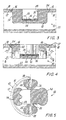
- the box 10 comprises a shell 12 the body 14 of which is formed as a container, which in this specific case (see plan view) is of overall circular shape and presents an open cavity 28.
- the shell 12 also presents a circular edge flange 16 forming one piece with the body 14.
- the flat outer face 15 of the flange 16 is coplanar with the outer face of the board 18 forming the relative outer surface of a plasterboard wall, the opposite outer surface of this wall consisting of a second board 22.
- the boards of the plasterboard wall can also be more than one per side, but this does not constitute a critical element.
- the circular flange 16 has a flared outer edge 17 (see Figures 2-4 in particular) in order to easily mate with the likewise flared edge of a circular aperture 24 previously made in the board 18.
- the circular aperture 24 can be made very easily and quickly using a common professional electric drill provided with a suitable bit (cup or circular ring shaped).
- two through holes 38 are provided in the flange 16 in symmetrical positions corresponding with two symmetrically opposing lateral recesses 32.
- each of the two toggle bolts 50 located in the relative recess 32, comprises a screw 52 with relative washer 58 and a toggle with two foldable arms 54 and 56.
- FIG. 1 clearly shows how the shell 12 is fixed by the toggle bolts 50.
- a split ring (not shown for simplicity) of intumescent fire retardant material can be inserted into the fixing holes 38, it being easily obtained from a commercially available strip of such material, as in the case of the base layer 36.
- Figure 1 shows means 29 for applying the box closure cover (not shown for simplicity) to the shell 12.
- these means can be plastic inserts embedded in the shell 18, to receive the relative screws to maintain the box cover in position.
- the box of the invention being precisely definable in all its characteristics, both dimensional and with regard to the materials used, can be certified by an authorized laboratory and is exactly reproducible.
- the intrinsic simplicity of the aforedescribed and illustrated box is also apparent, as is its ease of production (especially if the shell is formed of plaster or plaster-based material) and the simplicity and speed with which it can be installed, all of which is beneficially reflected in its production and installation costs.
- the use of the box 10 is not limited to plasterboard walls, but that it can be usefully used in all walls in which an aperture can be formed suitable to enable it to be received and be permanently fixed.
- the box can also be used in traditional masonry walls formed from perforated bricks and mortar.
Landscapes
- Engineering & Computer Science (AREA)
- Architecture (AREA)
- Civil Engineering (AREA)
- Structural Engineering (AREA)
- Connection Or Junction Boxes (AREA)
- Casings For Electric Apparatus (AREA)
- Installation Of Indoor Wiring (AREA)
Priority Applications (3)
| Application Number | Priority Date | Filing Date | Title |
|---|---|---|---|
| AT02004996T ATE475214T1 (de) | 2002-03-06 | 2002-03-06 | Elektro-installationsdose mit passiver feuerschutzeinrichtung |
| DE60237053T DE60237053D1 (de) | 2002-03-06 | 2002-03-06 | Elektro-Installationsdose mit passiver Feuerschutzeinrichtung |
| EP02004996A EP1221749B1 (fr) | 2002-03-06 | 2002-03-06 | Boîtier d'installation électrique à protection passive contre le feu |
Applications Claiming Priority (1)
| Application Number | Priority Date | Filing Date | Title |
|---|---|---|---|
| EP02004996A EP1221749B1 (fr) | 2002-03-06 | 2002-03-06 | Boîtier d'installation électrique à protection passive contre le feu |
Publications (2)
| Publication Number | Publication Date |
|---|---|
| EP1221749A1 true EP1221749A1 (fr) | 2002-07-10 |
| EP1221749B1 EP1221749B1 (fr) | 2010-07-21 |
Family
ID=8185441
Family Applications (1)
| Application Number | Title | Priority Date | Filing Date |
|---|---|---|---|
| EP02004996A Expired - Lifetime EP1221749B1 (fr) | 2002-03-06 | 2002-03-06 | Boîtier d'installation électrique à protection passive contre le feu |
Country Status (3)
| Country | Link |
|---|---|
| EP (1) | EP1221749B1 (fr) |
| AT (1) | ATE475214T1 (fr) |
| DE (1) | DE60237053D1 (fr) |
Cited By (6)
| Publication number | Priority date | Publication date | Assignee | Title |
|---|---|---|---|---|
| NL1023903C2 (nl) * | 2003-07-11 | 2005-01-12 | Cleo Holding B V | Elektrisch distributie- en verdeelsysteem met brandvertragende behoudsfunctie. |
| NL2005933C2 (nl) * | 2010-12-29 | 2012-07-03 | Abb Bv | Hollewanddoos met brandwerend inzetstuk. |
| DE102014108551B3 (de) * | 2014-06-17 | 2015-08-27 | Svt Brandschutz Vertriebsgesellschaft Mbh International | Brandschutz für Hohlwanddosen |
| GB2624952A (en) * | 2022-11-29 | 2024-06-05 | Intumescent Systems Ltd | Enclosures for electrical appliances |
| GB2625713A (en) * | 2022-11-29 | 2024-07-03 | Hoody Speaker Hoods Ltd | Covers for electrical appliances |
| FR3155376A1 (fr) | 2023-11-14 | 2025-05-16 | Legrand France | Accessoire coupe-feu à installer dans une boîte d’encastrement et ensemble coupe-feu comprenant une boîte d’encastrement et un tel accessoire coupe-feu |
Families Citing this family (1)
| Publication number | Priority date | Publication date | Assignee | Title |
|---|---|---|---|---|
| DK3280018T3 (da) | 2016-08-05 | 2020-07-27 | Abb Schweiz Ag | Elektrisk installationskasse med indsats af brandhæmmende materiale |
Citations (6)
| Publication number | Priority date | Publication date | Assignee | Title |
|---|---|---|---|---|
| US3995102A (en) * | 1974-01-25 | 1976-11-30 | Raceway Components, Inc. | Insert device for cables |
| DE2834189A1 (de) * | 1978-08-04 | 1980-02-14 | Rigips Baustoffwerke Gmbh | Hohlwanddose, insbesondere fuer elektrische installationen |
| US4616104A (en) * | 1984-11-16 | 1986-10-07 | Lindsey Travis C | Fire resistant electrical junction boxes |
| US4667840A (en) | 1984-11-16 | 1987-05-26 | Lindsey Travis C | Fire-resistant electrical junction boxes and method of manufacture |
| DE19831384A1 (de) * | 1998-07-14 | 2000-01-20 | Matthias Goepner | Baueinsatz mit erhöhtem Feuerwiderstandswert für Elektroinstallationselemente in Trockenbauwänden |
| EP1014523A1 (fr) * | 1998-12-22 | 2000-06-28 | Legrand | Boíte d'encastrement, notamment pour cloison sèche |
-
2002
- 2002-03-06 EP EP02004996A patent/EP1221749B1/fr not_active Expired - Lifetime
- 2002-03-06 DE DE60237053T patent/DE60237053D1/de not_active Expired - Lifetime
- 2002-03-06 AT AT02004996T patent/ATE475214T1/de not_active IP Right Cessation
Patent Citations (7)
| Publication number | Priority date | Publication date | Assignee | Title |
|---|---|---|---|---|
| US3995102A (en) * | 1974-01-25 | 1976-11-30 | Raceway Components, Inc. | Insert device for cables |
| US3995102B1 (fr) * | 1974-01-25 | 1985-10-08 | ||
| DE2834189A1 (de) * | 1978-08-04 | 1980-02-14 | Rigips Baustoffwerke Gmbh | Hohlwanddose, insbesondere fuer elektrische installationen |
| US4616104A (en) * | 1984-11-16 | 1986-10-07 | Lindsey Travis C | Fire resistant electrical junction boxes |
| US4667840A (en) | 1984-11-16 | 1987-05-26 | Lindsey Travis C | Fire-resistant electrical junction boxes and method of manufacture |
| DE19831384A1 (de) * | 1998-07-14 | 2000-01-20 | Matthias Goepner | Baueinsatz mit erhöhtem Feuerwiderstandswert für Elektroinstallationselemente in Trockenbauwänden |
| EP1014523A1 (fr) * | 1998-12-22 | 2000-06-28 | Legrand | Boíte d'encastrement, notamment pour cloison sèche |
Cited By (8)
| Publication number | Priority date | Publication date | Assignee | Title |
|---|---|---|---|---|
| NL1023903C2 (nl) * | 2003-07-11 | 2005-01-12 | Cleo Holding B V | Elektrisch distributie- en verdeelsysteem met brandvertragende behoudsfunctie. |
| NL2005933C2 (nl) * | 2010-12-29 | 2012-07-03 | Abb Bv | Hollewanddoos met brandwerend inzetstuk. |
| EP2472685A1 (fr) | 2010-12-29 | 2012-07-04 | Abb B.V. | Boîtier pour mur creux avec pièce insert résistante au feu |
| DE102014108551B3 (de) * | 2014-06-17 | 2015-08-27 | Svt Brandschutz Vertriebsgesellschaft Mbh International | Brandschutz für Hohlwanddosen |
| GB2624952A (en) * | 2022-11-29 | 2024-06-05 | Intumescent Systems Ltd | Enclosures for electrical appliances |
| GB2625713A (en) * | 2022-11-29 | 2024-07-03 | Hoody Speaker Hoods Ltd | Covers for electrical appliances |
| FR3155376A1 (fr) | 2023-11-14 | 2025-05-16 | Legrand France | Accessoire coupe-feu à installer dans une boîte d’encastrement et ensemble coupe-feu comprenant une boîte d’encastrement et un tel accessoire coupe-feu |
| EP4556077A1 (fr) | 2023-11-14 | 2025-05-21 | Legrand France | Accessoire coupe-feu à installer dans une boîte d'encastrement et ensemble coupe-feu comprenant une boîte d'encastrement et un tel accessoire coupe-feu |
Also Published As
| Publication number | Publication date |
|---|---|
| EP1221749B1 (fr) | 2010-07-21 |
| ATE475214T1 (de) | 2010-08-15 |
| DE60237053D1 (de) | 2010-09-02 |
Similar Documents
| Publication | Publication Date | Title |
|---|---|---|
| US6586679B2 (en) | Electrical junction box for construction panels | |
| US4667840A (en) | Fire-resistant electrical junction boxes and method of manufacture | |
| EP1221749B1 (fr) | Boîtier d'installation électrique à protection passive contre le feu | |
| CA2815721C (fr) | Methode pour realiser une penetration a protection contre les incendies dans un element de construction | |
| US20060261223A1 (en) | Wall-supporting device | |
| US20150211245A1 (en) | Free-standing form for building a pre-insulated wall and method of building a structure therewith | |
| US20180298605A1 (en) | Fire barrier box for membrane penetrations | |
| KR20090003503U (ko) | 레실리언트 채널을 이용한 건식벽체 | |
| JP7301442B2 (ja) | パネルユニット | |
| EP3280018B1 (fr) | Boîte d'installation électrique avec insert de matériau ignifuge | |
| KR102637816B1 (ko) | 경량벽체의 박스설치부위의 차음방화성능을 강화하고 복원하기 위한 차음방화철제박스 | |
| KR19990019928U (ko) | 조립건물용 패널 | |
| WO1996007043A1 (fr) | Supports | |
| CA2028929C (fr) | Boite de derivation/prise electrique | |
| CN222632641U (zh) | 一种含有线盒的预制混凝土砌块及其生产模具、墙体结构 | |
| EP2585646A1 (fr) | Élément de construction, et procédé pour fabriquer un tel élément de construction. | |
| US20060283119A1 (en) | Building unit and method of constructing buildings therewith | |
| KR100354717B1 (ko) | 일체형 벽을 사용한 조립식 욕실 | |
| EP3724545B1 (fr) | Un système constitué d'un scellement anti-incendie et ouverture dans le plancher ou le plafond d'un bâtiment et un procédé pour sceller une ouverture dans le plancher ou le plafond d'un bâtiment | |
| GB2449088A (en) | Insulation device for electrical outlets | |
| US20260071424A1 (en) | Device and method for producing and sealing a line feedthrough directly beneath a ceiling | |
| JPH1189048A (ja) | 連接配管接続用ボックス | |
| CA3263343A1 (fr) | Dispositif et méthode de production et d’étanchéité d’une conduite de câbles directement sous un plafond | |
| EP1835090A2 (fr) | Elément de conduit pour installations électriques et CVCS | |
| JPH0321146Y2 (fr) |
Legal Events
| Date | Code | Title | Description |
|---|---|---|---|
| PUAI | Public reference made under article 153(3) epc to a published international application that has entered the european phase |
Free format text: ORIGINAL CODE: 0009012 |
|
| AK | Designated contracting states |
Kind code of ref document: A1 Designated state(s): AT BE CH CY DE DK ES FI FR GB GR IE IT LI LU MC NL PT SE TR |
|
| AX | Request for extension of the european patent |
Free format text: AL;LT;LV;MK;RO;SI |
|
| 17P | Request for examination filed |
Effective date: 20021212 |
|
| AKX | Designation fees paid |
Designated state(s): AT BE CH CY DE DK ES FI FR GB GR IE IT LI LU MC NL PT SE TR |
|
| AXX | Extension fees paid |
Extension state: MK Payment date: 20021212 Extension state: LT Payment date: 20021212 Extension state: LV Payment date: 20021212 Extension state: AL Payment date: 20021212 Extension state: SI Payment date: 20021212 Extension state: RO Payment date: 20021212 |
|
| 17Q | First examination report despatched |
Effective date: 20090504 |
|
| GRAP | Despatch of communication of intention to grant a patent |
Free format text: ORIGINAL CODE: EPIDOSNIGR1 |
|
| GRAS | Grant fee paid |
Free format text: ORIGINAL CODE: EPIDOSNIGR3 |
|
| RAP1 | Party data changed (applicant data changed or rights of an application transferred) |
Owner name: MISURE CONTROLLI SICUREZZA S.AS. DI DAVIDE LURASCH |
|
| RAP1 | Party data changed (applicant data changed or rights of an application transferred) |
Owner name: MISURE CONTROLLI SICUREZZA S.AS. DI DAVIDE LURASCH |
|
| GRAA | (expected) grant |
Free format text: ORIGINAL CODE: 0009210 |
|
| AK | Designated contracting states |
Kind code of ref document: B1 Designated state(s): AT BE CH CY DE DK ES FI FR GB GR IE IT LI LU MC NL PT SE TR |
|
| AX | Request for extension of the european patent |
Extension state: AL LT LV MK RO SI |
|
| REG | Reference to a national code |
Ref country code: GB Ref legal event code: FG4D |
|
| REG | Reference to a national code |
Ref country code: CH Ref legal event code: EP |
|
| REG | Reference to a national code |
Ref country code: IE Ref legal event code: FG4D |
|
| REF | Corresponds to: |
Ref document number: 60237053 Country of ref document: DE Date of ref document: 20100902 Kind code of ref document: P |
|
| REG | Reference to a national code |
Ref country code: NL Ref legal event code: VDEP Effective date: 20100721 |
|
| LTIE | Lt: invalidation of european patent or patent extension |
Effective date: 20100721 |
|
| PG25 | Lapsed in a contracting state [announced via postgrant information from national office to epo] |
Ref country code: AT Free format text: LAPSE BECAUSE OF FAILURE TO SUBMIT A TRANSLATION OF THE DESCRIPTION OR TO PAY THE FEE WITHIN THE PRESCRIBED TIME-LIMIT Effective date: 20100721 Ref country code: FI Free format text: LAPSE BECAUSE OF FAILURE TO SUBMIT A TRANSLATION OF THE DESCRIPTION OR TO PAY THE FEE WITHIN THE PRESCRIBED TIME-LIMIT Effective date: 20100721 Ref country code: NL Free format text: LAPSE BECAUSE OF FAILURE TO SUBMIT A TRANSLATION OF THE DESCRIPTION OR TO PAY THE FEE WITHIN THE PRESCRIBED TIME-LIMIT Effective date: 20100721 |
|
| PG25 | Lapsed in a contracting state [announced via postgrant information from national office to epo] |
Ref country code: PT Free format text: LAPSE BECAUSE OF FAILURE TO SUBMIT A TRANSLATION OF THE DESCRIPTION OR TO PAY THE FEE WITHIN THE PRESCRIBED TIME-LIMIT Effective date: 20101122 Ref country code: CY Free format text: LAPSE BECAUSE OF FAILURE TO SUBMIT A TRANSLATION OF THE DESCRIPTION OR TO PAY THE FEE WITHIN THE PRESCRIBED TIME-LIMIT Effective date: 20100721 |
|
| PG25 | Lapsed in a contracting state [announced via postgrant information from national office to epo] |
Ref country code: BE Free format text: LAPSE BECAUSE OF FAILURE TO SUBMIT A TRANSLATION OF THE DESCRIPTION OR TO PAY THE FEE WITHIN THE PRESCRIBED TIME-LIMIT Effective date: 20100721 Ref country code: SE Free format text: LAPSE BECAUSE OF FAILURE TO SUBMIT A TRANSLATION OF THE DESCRIPTION OR TO PAY THE FEE WITHIN THE PRESCRIBED TIME-LIMIT Effective date: 20100721 Ref country code: GR Free format text: LAPSE BECAUSE OF FAILURE TO SUBMIT A TRANSLATION OF THE DESCRIPTION OR TO PAY THE FEE WITHIN THE PRESCRIBED TIME-LIMIT Effective date: 20101022 |
|
| PG25 | Lapsed in a contracting state [announced via postgrant information from national office to epo] |
Ref country code: DK Free format text: LAPSE BECAUSE OF FAILURE TO SUBMIT A TRANSLATION OF THE DESCRIPTION OR TO PAY THE FEE WITHIN THE PRESCRIBED TIME-LIMIT Effective date: 20100721 |
|
| PLBE | No opposition filed within time limit |
Free format text: ORIGINAL CODE: 0009261 |
|
| STAA | Information on the status of an ep patent application or granted ep patent |
Free format text: STATUS: NO OPPOSITION FILED WITHIN TIME LIMIT |
|
| 26N | No opposition filed |
Effective date: 20110426 |
|
| PG25 | Lapsed in a contracting state [announced via postgrant information from national office to epo] |
Ref country code: ES Free format text: LAPSE BECAUSE OF FAILURE TO SUBMIT A TRANSLATION OF THE DESCRIPTION OR TO PAY THE FEE WITHIN THE PRESCRIBED TIME-LIMIT Effective date: 20101101 |
|
| REG | Reference to a national code |
Ref country code: DE Ref legal event code: R097 Ref document number: 60237053 Country of ref document: DE Effective date: 20110426 |
|
| PG25 | Lapsed in a contracting state [announced via postgrant information from national office to epo] |
Ref country code: MC Free format text: LAPSE BECAUSE OF NON-PAYMENT OF DUE FEES Effective date: 20110331 |
|
| REG | Reference to a national code |
Ref country code: CH Ref legal event code: PL |
|
| GBPC | Gb: european patent ceased through non-payment of renewal fee |
Effective date: 20110306 |
|
| REG | Reference to a national code |
Ref country code: FR Ref legal event code: ST Effective date: 20111130 |
|
| REG | Reference to a national code |
Ref country code: IE Ref legal event code: MM4A |
|
| PG25 | Lapsed in a contracting state [announced via postgrant information from national office to epo] |
Ref country code: FR Free format text: LAPSE BECAUSE OF NON-PAYMENT OF DUE FEES Effective date: 20110331 Ref country code: IE Free format text: LAPSE BECAUSE OF NON-PAYMENT OF DUE FEES Effective date: 20110306 Ref country code: LI Free format text: LAPSE BECAUSE OF NON-PAYMENT OF DUE FEES Effective date: 20110331 Ref country code: CH Free format text: LAPSE BECAUSE OF NON-PAYMENT OF DUE FEES Effective date: 20110331 Ref country code: DE Free format text: LAPSE BECAUSE OF NON-PAYMENT OF DUE FEES Effective date: 20111001 |
|
| REG | Reference to a national code |
Ref country code: DE Ref legal event code: R119 Ref document number: 60237053 Country of ref document: DE Effective date: 20111001 |
|
| PG25 | Lapsed in a contracting state [announced via postgrant information from national office to epo] |
Ref country code: GB Free format text: LAPSE BECAUSE OF NON-PAYMENT OF DUE FEES Effective date: 20110306 |
|
| PGFP | Annual fee paid to national office [announced via postgrant information from national office to epo] |
Ref country code: IT Payment date: 20120227 Year of fee payment: 11 |
|
| PG25 | Lapsed in a contracting state [announced via postgrant information from national office to epo] |
Ref country code: LU Free format text: LAPSE BECAUSE OF NON-PAYMENT OF DUE FEES Effective date: 20110306 |
|
| PG25 | Lapsed in a contracting state [announced via postgrant information from national office to epo] |
Ref country code: TR Free format text: LAPSE BECAUSE OF FAILURE TO SUBMIT A TRANSLATION OF THE DESCRIPTION OR TO PAY THE FEE WITHIN THE PRESCRIBED TIME-LIMIT Effective date: 20100721 |
|
| PG25 | Lapsed in a contracting state [announced via postgrant information from national office to epo] |
Ref country code: IT Free format text: LAPSE BECAUSE OF NON-PAYMENT OF DUE FEES Effective date: 20140306 |