EP1320162A1 - Boíte de distribution en plastique montée au mur - Google Patents
Boíte de distribution en plastique montée au mur Download PDFInfo
- Publication number
- EP1320162A1 EP1320162A1 EP20020022007 EP02022007A EP1320162A1 EP 1320162 A1 EP1320162 A1 EP 1320162A1 EP 20020022007 EP20020022007 EP 20020022007 EP 02022007 A EP02022007 A EP 02022007A EP 1320162 A1 EP1320162 A1 EP 1320162A1
- Authority
- EP
- European Patent Office
- Prior art keywords
- box
- cavity wall
- double
- wall
- collar
- Prior art date
- Legal status (The legal status is an assumption and is not a legal conclusion. Google has not performed a legal analysis and makes no representation as to the accuracy of the status listed.)
- Granted
Links
- 238000003780 insertion Methods 0.000 claims abstract description 8
- 230000037431 insertion Effects 0.000 claims abstract description 8
- 238000009434 installation Methods 0.000 claims description 38
- 238000007789 sealing Methods 0.000 claims description 11
- 238000010616 electrical installation Methods 0.000 claims description 4
- 230000003993 interaction Effects 0.000 abstract 1
- 230000002093 peripheral effect Effects 0.000 abstract 1
- 238000005192 partition Methods 0.000 description 17
- 238000013461 design Methods 0.000 description 2
- 238000009413 insulation Methods 0.000 description 2
- 238000000034 method Methods 0.000 description 2
- 238000000926 separation method Methods 0.000 description 2
- 230000004913 activation Effects 0.000 description 1
- 239000000969 carrier Substances 0.000 description 1
- 150000001875 compounds Chemical class 0.000 description 1
- 238000011161 development Methods 0.000 description 1
- 238000012423 maintenance Methods 0.000 description 1
- 238000004519 manufacturing process Methods 0.000 description 1
- 239000000463 material Substances 0.000 description 1
- 239000011505 plaster Substances 0.000 description 1
- 238000012549 training Methods 0.000 description 1
- 230000007704 transition Effects 0.000 description 1
Images


Classifications
-
- H—ELECTRICITY
- H02—GENERATION; CONVERSION OR DISTRIBUTION OF ELECTRIC POWER
- H02G—INSTALLATION OF ELECTRIC CABLES OR LINES, OR OF COMBINED OPTICAL AND ELECTRIC CABLES OR LINES
- H02G3/00—Installations of electric cables or lines or protective tubing therefor in or on buildings, equivalent structures or vehicles
- H02G3/02—Details
- H02G3/08—Distribution boxes; Connection or junction boxes
- H02G3/12—Distribution boxes; Connection or junction boxes for flush mounting
- H02G3/121—Distribution boxes; Connection or junction boxes for flush mounting in plain walls
-
- H—ELECTRICITY
- H02—GENERATION; CONVERSION OR DISTRIBUTION OF ELECTRIC POWER
- H02G—INSTALLATION OF ELECTRIC CABLES OR LINES, OR OF COMBINED OPTICAL AND ELECTRIC CABLES OR LINES
- H02G3/00—Installations of electric cables or lines or protective tubing therefor in or on buildings, equivalent structures or vehicles
- H02G3/02—Details
- H02G3/08—Distribution boxes; Connection or junction boxes
- H02G3/12—Distribution boxes; Connection or junction boxes for flush mounting
- H02G3/123—Distribution boxes; Connection or junction boxes for flush mounting in thin walls
Definitions
- the invention relates to a cavity wall box Plastic for electrical installations, the front into the breakthrough of a wall can be used, the cavity wall box one Insert collar to flush Insert in the breakthrough and on the circumference Holding surfaces or edges to interact with the perforation of the opening in the wall has, as well as the cavity wall box final floor.
- a generic cavity wall box is from the DE 196 09 709 A1 known. Such cavity wall boxes are for electrical installations like for example switches, sockets or the like is useful. These are cavity wall boxes in a simple way in the breakthrough of a Cavity wall can be used by a circular Breakthrough is created in the wall the hollow wall box, which is cylindrical in cross section can be used.
- the breakthrough is marked with a Edge countersink machined, so that at the Mouth of the cavity wall box located Insertion depth limiting collar sunk into the Breakthrough is used and the can is arranged flush in the opening.
- Insertion depth limiting collar sunk into the Breakthrough is used and the can is arranged flush in the opening.
- the cavity wall box in the opening are usually set screws with corresponding holding members on the outside of the box provided and supported on the can, the corresponding screws from the front of the Can forth are accessible to the holding member on the back against the wall next to the opening press on and so for a secure fit of the To worry about cavity wall box.
- the cavity wall box itself shows a closed outer surface and one closed ground in which, if necessary can be broken out, cut out or punched out Breakthroughs for inserting cables or the like can be set.
- Breakthroughs can be arranged in the wall, so that two cavity wall boxes right next to each other can be arranged.
- the Breakthroughs into which the cavity wall boxes can be inserted are merging so that the Sealing function in the immediately adjacent Area of interlocking breakthroughs is not or not sufficiently guaranteed.
- the assembler must ensure that both cans exactly correct and at the same level are positioned.
- Such neighboring cans can be through a Combination connecting pieces are connected so that Lines from one socket to the other can be.
- the cavity wall box as oval in plan view Double box is formed.
- the cavity wall box as an oval Double socket is formed, this is one hand for example to accommodate two juxtaposed switches, sockets or the like, suitable in the usual way attached to the cavity wall box using support rings can be.
- the cavity wall box it is in a breakthrough of a wall only required two circular Provide openings in the wall, the Center axes are spaced from each other, the the distance between the central axes of the partial circles correspond to the double can.
- the one between them Holes can remain in the gusset simply manually or by means of a Be removed so that the corresponding breakthrough also oval is formed and the semicircles of the oval Wall breakthrough tangentially into a straight line Skip transition area.
- the oval double box can be used for the recess so that the double box matches the corresponding Wall opening largely windproof be upheld.
- the double box is formed by a can body that at least in the area of the collar and the Holding surfaces or edges at its longitudinal ends is rounded in a semicircle, the two Semicircular shapes over straight connection areas are connected, and that the collar only radially protruding in the area of the semicircular shapes is provided and the holding surfaces or edges by a semicircular shape and straight Connection areas surrounding uninterrupted radially projecting surface area or Edge area are formed.
- the double can has a can body on the at least close to its mouth
- Longitudinal ends are rounded in a semicircle, so that the end areas by cylindrical sections are formed in a semicircular shape that over straight Connection areas are connected, which also Extension directed parallel to the hole reveal exhibit.
- These areas should have at least one have such a height that the area itself extends over the entire height of the hole reveal. 0b and in how far the can beyond Reveal hole is tapered or other shape is not for the further facts crucial. It is only important that the Can in the immediate area of access Hole reveal of this adapted shape and height having. They have a semicircular shape rounded sections at the mouth of the can radially protruding collar.
- This Collar form the Insertion depth limit stops the appropriate recording space for the Collar parts in turn by a countersink or the like can be created, the when creating the circular shape of the corresponding Recess or breakthrough is used.
- the area of the two semicircular shapes are connecting areas connecting in a straight line such a collar is not provided because the corresponding straight connection areas not in simple way with a countersink can be edited. Because of the chosen It is possible to design the appropriate one Cavity wall box flush in the corresponding Recess or the breakthrough of the wall use.
- the double box At a distance from the mouth of the The double box is one around the entire box Holding surface or edge, for example in Form of a rib provided in the Desired installation situation all around on the perforation near the rear end in the direction of insertion Reveal holes so that a tight Arrangement of the double box in the corresponding Recess is guaranteed.
- a partition or a Intermediate bridge can be used, with inserted intermediate bridge or with inserted Partition the straight connection areas against the perforation of the opening is pressed.
- the double can inside and opposite each other in the Area in the middle between the semicircular shapes Has insertion grooves into which the partition or the intermediate bridge from the can mouth can be inserted.
- the partition in the inserted in the double box Target installation position the two installation locations completely separates the double box from one another.
- the cavity wall box according to the invention is not only for the installation of two usual Installation devices usable, but it is also possible in the one installation room for example an electronic component, a Transformer, a circuit arrangement or a to accommodate other electrical arrangement that does not have to be accessible from the outside and the for example with the other Installation space arranged installation part is in operative connection.
- the installation space too cover in which no installation device such as arranged for example switch or socket is.
- a half cover be provided is that flush with the mouth of the double can can be used and one of the two Installation places covered.
- the corresponding half-cover can alternatively be used one of the two installation locations so this installation space is covered.
- notches and notches are mainly in the area between the Mouth edge and that as a sealing surface or Sealing edge serving holding surfaces or Holding edges provided so that the Overall, the can is windproof Recesses is not affected.
- the Half cover as a tub-like molded part with a Floor and surrounding, protruding from the floor Collar is formed, the lid alternatively with the surrounding collar in the mouth of the double can be used, so that the bottom at the estuary level of the Double box sits or flush with this completes, or with the floor ahead in the Mouth can be used so that the bottom opposite edge of the collar in the mouth plane the double box sits or is flush with it concludes.
- the half cover with the ground first in the mouth of the Insert cavity wall box so that one of the both installation locations is covered, whereby the floor then lies behind the mouth.
- the order is preferably in combination with the Partition or the like provided that the half-cover is the one installation place covers, but not the upper front edge of the Partition or the like so that the Partition also in the target position located half cover can be removed or can be inserted.
- the partition forms another Support for the half cover, which is immovable between partition and the surrounding Mouth of the one installation site of the Double box is arranged.
- the collar of the half-cover is stiffened by supporting webs.
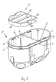
- a cavity wall box 1 which is molded from plastic and for serves electrical installations.
- a such cavity wall box 1 is known per se Way ahead in the breakthrough one Wall of a cavity wall area can be used.
- the cavity wall box points to the positioning an insertion depth limiting collar 2, see above that the cavity wall box is flush with the appropriate wall opening can be used, by the recess of the breakthrough through a rotating element is generated and the edge of the Machined recess by a countersink becomes. This makes it possible for the collar 2 flush in the wall in the the breakthrough is made.
- the cavity wall box 1 is only on the muzzle side (in FIG. 1 above) open while the walls and bottom of the Can are closed. In the bottom of the can for example, cut-out areas are provided be to put cables or the like in the can to be able to introduce. Furthermore, on Outer jacket of the box 1 facilities 4 provided in the fastening screws together Holding elements can be introduced to the To be able to clamp the can on the hollow wall. Such devices are not in the drawing shown. But they are common and well known.
- Such facilities are in the DE 196 09 709 A1 shown.
- 1 arrangements 5 are provided on the inside of the can, on which support rings of service equipment carriers or the like fastened by means of screws can be.
- the cavity wall box 1 is in total Top view designed as an oval double box.
- the Double can is formed by a can body, the at least in the area where the collar 2 and the holding surface or edge 3 or Sealing edge is arranged at the longitudinal ends is rounded in a semicircle, the two Semicircular shapes over straight connection areas 6 are connected.
- the collar 2 is only in the Range of semicircular shapes radially outwards provided protruding.
- the holding surfaces or Sealing edges 3 are semicircular in shape and the straight connection areas 6 uninterrupted surrounding radially projecting Surface area or edge area formed.
- the Width of the area between parts 2 and 3 is equal to or greater than the thickness of the wall, in which the breakthrough to accommodate the Cavity wall box 1 is introduced so that on the one hand the collar 2 is flush with the surface of the The wall lies and on the other hand the sealing edge 3 is still in the engagement area of the hole reveal.
- the cavity wall box 1 In the middle between the two semicircular shapes is the cavity wall box 1 an intermediate wall 7 used, being used by the Partition 7 the straight connection areas 6 in the target assembly position against the perforation of the Breakthrough of the wall are pressed.
- the Cavity wall box 1 faces inside and each other opposite in the area between the middle Semicircular shapes, i.e. in the area of the straight Connection areas 6, slots 8 on, in which the partition 7 from the can mouth can be inserted here.
- two installation locations of the double box completely separate from each other or one Installation gap for performing electrical lines or the like exhibit.
- a special development of the cavity wall box 1 provides that a half cover 9 is provided, in the mouth of the as a double can trained cavity wall box 1 can be used flush is, as is the case, for example, with reference to FIG. 3 is made clear so that one of the two Installation places is covered.
- the half cover for this purpose, 9 can have locking projections 10, which in Locking recesses 11 in the installation target position intervention.
- the locking recesses 11 are in an area between the collar 2 and the Sealing edge 3 is provided so that the These openings make the can windproof is not affected.
- the half cover 9 is a trough-like molded part with a bottom 12 and protruding from the bottom, circumferential collar 13, the Half-cover 9 with the circumferential collar 13 ahead can be inserted into the mouth of the double can, such as this is illustrated in Figure 1, so that the Floor 12 in the target mounting position in the Mouth level of the double box sits flush with this concludes.
- the half cover 9 also with the ground ahead in the mouth of the Cavity wall box 1 can be used, as in Figure 2 and 3 is clarified so that the Bottom 12 facing edge of the collar 13 in the Mouth level of the double can sits or with this is flush.
- the collar 13 of the half cover 9 is preferably stiffened by support webs 14.
- the half cover 9 points in the area of the arrangement of the functional parts 4 or 5 of the cavity wall box 1 on the edge Bulges so that these components are the Do not disturb inserting the lid. It can this area by a removable Material layer 15 may be covered, so that each according to the installation method with the Half-cover 9, the components 4 and 5 of covered installation space are covered or in the installation method according to Figure 2 and 3 a passage for the ends of parts 4 and 5 is created.
- the invention is not based on that Embodiment limited, but in the frame Revelation is often variable.
Landscapes
- Engineering & Computer Science (AREA)
- Architecture (AREA)
- Civil Engineering (AREA)
- Structural Engineering (AREA)
- Connection Or Junction Boxes (AREA)
- Casings For Electric Apparatus (AREA)
Applications Claiming Priority (2)
| Application Number | Priority Date | Filing Date | Title |
|---|---|---|---|
| DE10160736A DE10160736B4 (de) | 2001-12-11 | 2001-12-11 | Hohlwanddose aus Kunststoff |
| DE10160736 | 2001-12-11 |
Publications (2)
| Publication Number | Publication Date |
|---|---|
| EP1320162A1 true EP1320162A1 (fr) | 2003-06-18 |
| EP1320162B1 EP1320162B1 (fr) | 2015-12-30 |
Family
ID=7708751
Family Applications (1)
| Application Number | Title | Priority Date | Filing Date |
|---|---|---|---|
| EP02022007.5A Expired - Lifetime EP1320162B1 (fr) | 2001-12-11 | 2002-10-01 | Boîte de distribution en plastique montée au mur |
Country Status (2)
| Country | Link |
|---|---|
| EP (1) | EP1320162B1 (fr) |
| DE (1) | DE10160736B4 (fr) |
Cited By (2)
| Publication number | Priority date | Publication date | Assignee | Title |
|---|---|---|---|---|
| WO2008008198A1 (fr) * | 2006-07-07 | 2008-01-17 | Lutron Electronics Co., Inc. | dispositif de commande de charge ayant une enceinte en deux parties |
| GB2572814A (en) * | 2018-04-12 | 2019-10-16 | Circle Box Ltd | Improved Electrical Back Box |
Families Citing this family (2)
| Publication number | Priority date | Publication date | Assignee | Title |
|---|---|---|---|---|
| DE10343489A1 (de) * | 2003-09-19 | 2005-04-14 | Comatec S.N.C. | Transformator, insbesondere Sicherheitstransformator zum Einbau in Unterputzdosen |
| BE1020602A3 (de) * | 2012-04-04 | 2014-01-07 | Kaiser Gmbh & Co Kg | Hohlwanddose aus kunststoff. |
Citations (3)
| Publication number | Priority date | Publication date | Assignee | Title |
|---|---|---|---|---|
| DE2526853A1 (de) * | 1975-06-16 | 1977-01-13 | Kaiser Kg | Elektrische einbaudose |
| DE4222042A1 (de) * | 1992-04-29 | 1994-01-05 | Kaiser Gmbh & Co Kg | Elektrische Abzweigdose, insbesondere für den Installationsbus |
| EP1014523A1 (fr) * | 1998-12-22 | 2000-06-28 | Legrand | Boíte d'encastrement, notamment pour cloison sèche |
Family Cites Families (1)
| Publication number | Priority date | Publication date | Assignee | Title |
|---|---|---|---|---|
| DE19609709C2 (de) * | 1996-03-13 | 1999-05-20 | Kaiser Gmbh & Co Kg | Elektrische Hohlwanddose |
-
2001
- 2001-12-11 DE DE10160736A patent/DE10160736B4/de not_active Expired - Fee Related
-
2002
- 2002-10-01 EP EP02022007.5A patent/EP1320162B1/fr not_active Expired - Lifetime
Patent Citations (3)
| Publication number | Priority date | Publication date | Assignee | Title |
|---|---|---|---|---|
| DE2526853A1 (de) * | 1975-06-16 | 1977-01-13 | Kaiser Kg | Elektrische einbaudose |
| DE4222042A1 (de) * | 1992-04-29 | 1994-01-05 | Kaiser Gmbh & Co Kg | Elektrische Abzweigdose, insbesondere für den Installationsbus |
| EP1014523A1 (fr) * | 1998-12-22 | 2000-06-28 | Legrand | Boíte d'encastrement, notamment pour cloison sèche |
Cited By (5)
| Publication number | Priority date | Publication date | Assignee | Title |
|---|---|---|---|---|
| WO2008008198A1 (fr) * | 2006-07-07 | 2008-01-17 | Lutron Electronics Co., Inc. | dispositif de commande de charge ayant une enceinte en deux parties |
| US7375951B2 (en) | 2006-07-07 | 2008-05-20 | Lutron Electronics Co., Inc. | Load control device having a split enclosure |
| CN101507357B (zh) * | 2006-07-07 | 2012-09-26 | 路创电子公司 | 具有分离式外壳的负载控制装置 |
| GB2572814A (en) * | 2018-04-12 | 2019-10-16 | Circle Box Ltd | Improved Electrical Back Box |
| GB2572814B (en) * | 2018-04-12 | 2022-07-13 | Circle Box Ltd | Improved Electrical Back Box |
Also Published As
| Publication number | Publication date |
|---|---|
| EP1320162B1 (fr) | 2015-12-30 |
| DE10160736B4 (de) | 2004-07-29 |
| DE10160736A1 (de) | 2003-06-26 |
Similar Documents
| Publication | Publication Date | Title |
|---|---|---|
| DE2711324C2 (de) | Gehäusebausatz für elektrische Installationsgeräte, insbesondere von Sprech- und/oder Klingelanlagen | |
| DE4436147C2 (de) | Geräteeinbaudose für Installationskanäle | |
| EP0957553B1 (fr) | Goulotte de câbles | |
| DE10160736B4 (de) | Hohlwanddose aus Kunststoff | |
| EP0957552B1 (fr) | Boítier pour appareillage d'installation électrique | |
| DE3920964C2 (fr) | ||
| DE3817100A1 (de) | Unterputzdose fuer insbesondere mauerwerks- und hohlwandmontage | |
| DE20120003U1 (de) | Hohlwanddose aus Kunststoff | |
| DE102014102260B4 (de) | Baukasten für die Abdichtung des Durchganges von Kabeln oder Adern, die durch eine Platte verlaufen sowie Verfahren zum Abdichten | |
| DE3906366A1 (de) | Lampenfassung fuer kraftfahrzeuge | |
| DE3842205C2 (de) | Gehäuse für den Anschluß von Kommunikationssystemen | |
| EP2650994B1 (fr) | Agencement de prises pour canaux d'intégration d'appareils avec rail de maintien sur le fond du canal et canal d'intégration d'appareils comprenant un tel agencement de prises | |
| DE2918530A1 (de) | Halterung, insbesondere zur verlegung und befestigung von rohren von fussbodenheizungen auf fussboeden | |
| DE102008017108B4 (de) | Elektroinstallationseinrichtung und System aus nebeneinander angeordneten Elektroinstallationseinrichtungen | |
| EP0062135A2 (fr) | Armoire étanche aux projections d'eau pour appareils électriques tels que des automates, des fusibles, des bornes, des compteurs électriques et analogues | |
| AT413165B (de) | Anordnung bestehend aus einem rahmen und einer montageplatte | |
| EP3540884A1 (fr) | Boîte d'installation et entrée de boîte d'installation | |
| EP0508175A2 (fr) | Boîte de distribution à but électro-technique à monter sur crépi | |
| EP3716427B1 (fr) | Plaque de bride pour le montage dans une percée d'une paroi de boîtier | |
| DE19845335A1 (de) | Geräteaufnahme für eine Unterflurgerätedose | |
| EP1638180A1 (fr) | Protection de terminaison d'un isolateur | |
| DE4103852A1 (de) | Moebel-einbaubox | |
| EP1132682A2 (fr) | Corps creux pour une installation électrique | |
| DE202008009377U1 (de) | Kabeldurchlaß | |
| DE660340C (de) | Mehrteilige Mehrfachsteckdose |
Legal Events
| Date | Code | Title | Description |
|---|---|---|---|
| PUAI | Public reference made under article 153(3) epc to a published international application that has entered the european phase |
Free format text: ORIGINAL CODE: 0009012 |
|
| AK | Designated contracting states |
Designated state(s): AT BE BG CH CY CZ DE DK EE ES FI FR GB GR IE IT LI LU MC NL PT SE SK TR |
|
| AX | Request for extension of the european patent |
Extension state: AL LT LV MK RO SI |
|
| 17P | Request for examination filed |
Effective date: 20030710 |
|
| AKX | Designation fees paid |
Designated state(s): AT BE BG CH CY CZ DE DK EE ES FI FR GB GR IE IT LI LU MC NL PT SE SK TR |
|
| 17Q | First examination report despatched |
Effective date: 20150312 |
|
| GRAP | Despatch of communication of intention to grant a patent |
Free format text: ORIGINAL CODE: EPIDOSNIGR1 |
|
| INTG | Intention to grant announced |
Effective date: 20150729 |
|
| GRAS | Grant fee paid |
Free format text: ORIGINAL CODE: EPIDOSNIGR3 |
|
| GRAA | (expected) grant |
Free format text: ORIGINAL CODE: 0009210 |
|
| AK | Designated contracting states |
Kind code of ref document: B1 Designated state(s): AT BE BG CH CY CZ DE DK EE ES FI FR GB GR IE IT LI LU MC NL PT SE SK TR |
|
| REG | Reference to a national code |
Ref country code: GB Ref legal event code: FG4D Free format text: NOT ENGLISH |
|
| REG | Reference to a national code |
Ref country code: CH Ref legal event code: EP |
|
| REG | Reference to a national code |
Ref country code: AT Ref legal event code: REF Ref document number: 767862 Country of ref document: AT Kind code of ref document: T Effective date: 20160115 |
|
| REG | Reference to a national code |
Ref country code: IE Ref legal event code: FG4D Free format text: LANGUAGE OF EP DOCUMENT: GERMAN |
|
| REG | Reference to a national code |
Ref country code: DE Ref legal event code: R096 Ref document number: 50216111 Country of ref document: DE |
|
| REG | Reference to a national code |
Ref country code: NL Ref legal event code: MP Effective date: 20151230 |
|
| PG25 | Lapsed in a contracting state [announced via postgrant information from national office to epo] |
Ref country code: SE Free format text: LAPSE BECAUSE OF FAILURE TO SUBMIT A TRANSLATION OF THE DESCRIPTION OR TO PAY THE FEE WITHIN THE PRESCRIBED TIME-LIMIT Effective date: 20151230 Ref country code: GR Free format text: LAPSE BECAUSE OF FAILURE TO SUBMIT A TRANSLATION OF THE DESCRIPTION OR TO PAY THE FEE WITHIN THE PRESCRIBED TIME-LIMIT Effective date: 20160331 Ref country code: FI Free format text: LAPSE BECAUSE OF FAILURE TO SUBMIT A TRANSLATION OF THE DESCRIPTION OR TO PAY THE FEE WITHIN THE PRESCRIBED TIME-LIMIT Effective date: 20151230 |
|
| PG25 | Lapsed in a contracting state [announced via postgrant information from national office to epo] |
Ref country code: NL Free format text: LAPSE BECAUSE OF FAILURE TO SUBMIT A TRANSLATION OF THE DESCRIPTION OR TO PAY THE FEE WITHIN THE PRESCRIBED TIME-LIMIT Effective date: 20151230 |
|
| PG25 | Lapsed in a contracting state [announced via postgrant information from national office to epo] |
Ref country code: IT Free format text: LAPSE BECAUSE OF FAILURE TO SUBMIT A TRANSLATION OF THE DESCRIPTION OR TO PAY THE FEE WITHIN THE PRESCRIBED TIME-LIMIT Effective date: 20151230 Ref country code: ES Free format text: LAPSE BECAUSE OF FAILURE TO SUBMIT A TRANSLATION OF THE DESCRIPTION OR TO PAY THE FEE WITHIN THE PRESCRIBED TIME-LIMIT Effective date: 20151230 Ref country code: CZ Free format text: LAPSE BECAUSE OF FAILURE TO SUBMIT A TRANSLATION OF THE DESCRIPTION OR TO PAY THE FEE WITHIN THE PRESCRIBED TIME-LIMIT Effective date: 20151230 |
|
| PG25 | Lapsed in a contracting state [announced via postgrant information from national office to epo] |
Ref country code: SK Free format text: LAPSE BECAUSE OF FAILURE TO SUBMIT A TRANSLATION OF THE DESCRIPTION OR TO PAY THE FEE WITHIN THE PRESCRIBED TIME-LIMIT Effective date: 20151230 Ref country code: PT Free format text: LAPSE BECAUSE OF FAILURE TO SUBMIT A TRANSLATION OF THE DESCRIPTION OR TO PAY THE FEE WITHIN THE PRESCRIBED TIME-LIMIT Effective date: 20160502 Ref country code: EE Free format text: LAPSE BECAUSE OF FAILURE TO SUBMIT A TRANSLATION OF THE DESCRIPTION OR TO PAY THE FEE WITHIN THE PRESCRIBED TIME-LIMIT Effective date: 20151230 |
|
| REG | Reference to a national code |
Ref country code: DE Ref legal event code: R097 Ref document number: 50216111 Country of ref document: DE |
|
| PG25 | Lapsed in a contracting state [announced via postgrant information from national office to epo] |
Ref country code: DK Free format text: LAPSE BECAUSE OF FAILURE TO SUBMIT A TRANSLATION OF THE DESCRIPTION OR TO PAY THE FEE WITHIN THE PRESCRIBED TIME-LIMIT Effective date: 20151230 |
|
| PLBE | No opposition filed within time limit |
Free format text: ORIGINAL CODE: 0009261 |
|
| STAA | Information on the status of an ep patent application or granted ep patent |
Free format text: STATUS: NO OPPOSITION FILED WITHIN TIME LIMIT |
|
| 26N | No opposition filed |
Effective date: 20161003 |
|
| PG25 | Lapsed in a contracting state [announced via postgrant information from national office to epo] |
Ref country code: BE Free format text: LAPSE BECAUSE OF NON-PAYMENT OF DUE FEES Effective date: 20161031 |
|
| REG | Reference to a national code |
Ref country code: CH Ref legal event code: PL |
|
| GBPC | Gb: european patent ceased through non-payment of renewal fee |
Effective date: 20161001 |
|
| REG | Reference to a national code |
Ref country code: IE Ref legal event code: MM4A |
|
| REG | Reference to a national code |
Ref country code: FR Ref legal event code: ST Effective date: 20170630 |
|
| PG25 | Lapsed in a contracting state [announced via postgrant information from national office to epo] |
Ref country code: CH Free format text: LAPSE BECAUSE OF NON-PAYMENT OF DUE FEES Effective date: 20161031 Ref country code: FR Free format text: LAPSE BECAUSE OF NON-PAYMENT OF DUE FEES Effective date: 20161102 Ref country code: LI Free format text: LAPSE BECAUSE OF NON-PAYMENT OF DUE FEES Effective date: 20161031 Ref country code: GB Free format text: LAPSE BECAUSE OF NON-PAYMENT OF DUE FEES Effective date: 20161001 |
|
| PG25 | Lapsed in a contracting state [announced via postgrant information from national office to epo] |
Ref country code: LU Free format text: LAPSE BECAUSE OF NON-PAYMENT OF DUE FEES Effective date: 20161001 |
|
| PG25 | Lapsed in a contracting state [announced via postgrant information from national office to epo] |
Ref country code: IE Free format text: LAPSE BECAUSE OF NON-PAYMENT OF DUE FEES Effective date: 20161001 |
|
| REG | Reference to a national code |
Ref country code: BE Ref legal event code: MM Effective date: 20161031 |
|
| REG | Reference to a national code |
Ref country code: AT Ref legal event code: MM01 Ref document number: 767862 Country of ref document: AT Kind code of ref document: T Effective date: 20161001 |
|
| PG25 | Lapsed in a contracting state [announced via postgrant information from national office to epo] |
Ref country code: AT Free format text: LAPSE BECAUSE OF NON-PAYMENT OF DUE FEES Effective date: 20161001 |
|
| PG25 | Lapsed in a contracting state [announced via postgrant information from national office to epo] |
Ref country code: CY Free format text: LAPSE BECAUSE OF FAILURE TO SUBMIT A TRANSLATION OF THE DESCRIPTION OR TO PAY THE FEE WITHIN THE PRESCRIBED TIME-LIMIT Effective date: 20151230 |
|
| PG25 | Lapsed in a contracting state [announced via postgrant information from national office to epo] |
Ref country code: MC Free format text: LAPSE BECAUSE OF FAILURE TO SUBMIT A TRANSLATION OF THE DESCRIPTION OR TO PAY THE FEE WITHIN THE PRESCRIBED TIME-LIMIT Effective date: 20151230 Ref country code: TR Free format text: LAPSE BECAUSE OF FAILURE TO SUBMIT A TRANSLATION OF THE DESCRIPTION OR TO PAY THE FEE WITHIN THE PRESCRIBED TIME-LIMIT Effective date: 20151230 |
|
| PG25 | Lapsed in a contracting state [announced via postgrant information from national office to epo] |
Ref country code: BG Free format text: LAPSE BECAUSE OF FAILURE TO SUBMIT A TRANSLATION OF THE DESCRIPTION OR TO PAY THE FEE WITHIN THE PRESCRIBED TIME-LIMIT Effective date: 20151230 |
|
| PGFP | Annual fee paid to national office [announced via postgrant information from national office to epo] |
Ref country code: DE Payment date: 20211229 Year of fee payment: 20 |
|
| REG | Reference to a national code |
Ref country code: DE Ref legal event code: R071 Ref document number: 50216111 Country of ref document: DE |