EP1014531A2 - Appareil d'alimentation en énergie électrique pour composants électroniques anti-déflagrant - Google Patents
Appareil d'alimentation en énergie électrique pour composants électroniques anti-déflagrant Download PDFInfo
- Publication number
- EP1014531A2 EP1014531A2 EP99125477A EP99125477A EP1014531A2 EP 1014531 A2 EP1014531 A2 EP 1014531A2 EP 99125477 A EP99125477 A EP 99125477A EP 99125477 A EP99125477 A EP 99125477A EP 1014531 A2 EP1014531 A2 EP 1014531A2
- Authority
- EP
- European Patent Office
- Prior art keywords
- particular according
- module
- coil
- voltage
- carrier
- Prior art date
- Legal status (The legal status is an assumption and is not a legal conclusion. Google has not performed a legal analysis and makes no representation as to the accuracy of the status listed.)
- Granted
Links
Images










Classifications
-
- H—ELECTRICITY
- H02—GENERATION; CONVERSION OR DISTRIBUTION OF ELECTRIC POWER
- H02J—ELECTRIC POWER NETWORKS; CIRCUIT ARRANGEMENTS OR SYSTEMS FOR SUPPLYING OR DISTRIBUTING ELECTRIC POWER; SYSTEMS FOR STORING ELECTRIC ENERGY
- H02J50/00—Circuit arrangements or systems for wireless supply or distribution of electric power
- H02J50/40—Circuit arrangements or systems for wireless supply or distribution of electric power using two or more transmitting or receiving devices
- H02J50/402—Circuit arrangements or systems for wireless supply or distribution of electric power using two or more transmitting or receiving devices the two or more transmitting or the two or more receiving devices being integrated in the same unit, e.g. power mats with several coils or antennas with several sub-antennas
-
- H—ELECTRICITY
- H02—GENERATION; CONVERSION OR DISTRIBUTION OF ELECTRIC POWER
- H02J—ELECTRIC POWER NETWORKS; CIRCUIT ARRANGEMENTS OR SYSTEMS FOR SUPPLYING OR DISTRIBUTING ELECTRIC POWER; SYSTEMS FOR STORING ELECTRIC ENERGY
- H02J50/00—Circuit arrangements or systems for wireless supply or distribution of electric power
- H02J50/10—Circuit arrangements or systems for wireless supply or distribution of electric power using inductive coupling
-
- H—ELECTRICITY
- H02—GENERATION; CONVERSION OR DISTRIBUTION OF ELECTRIC POWER
- H02J—ELECTRIC POWER NETWORKS; CIRCUIT ARRANGEMENTS OR SYSTEMS FOR SUPPLYING OR DISTRIBUTING ELECTRIC POWER; SYSTEMS FOR STORING ELECTRIC ENERGY
- H02J50/00—Circuit arrangements or systems for wireless supply or distribution of electric power
- H02J50/10—Circuit arrangements or systems for wireless supply or distribution of electric power using inductive coupling
- H02J50/12—Circuit arrangements or systems for wireless supply or distribution of electric power using inductive coupling of the resonant type
Definitions
- the invention relates to a device for energy supply for explosion-protected functional units.
- the invention further relates to a device for Power supply of a variety of on a common Carrier of pluggable electronic functional units in a hazardous area from an operating voltage source. It is in the prior art known, a number of headers on a carrier board in which functional units, For example, plug-in cards or other modules can be inserted can. Data line contacts are made via the connector strips closed and power supply line contacts.
- the invention is based on the object at the outset Describe devices described more reliable.
- the choke is preferably a capacitor or a coil.
- the capacity of the The capacitor or the inductance of the coil is included in this way to the output frequency of the output AC voltage adapted that there is a suitable reactance results.
- Suitable reactances can be found in Range between 1 and 1000 ohms. As capacities preferably values between 1 nF and 10 nF come in Consideration. Coils from 1 ⁇ H to are used as choke coils 10 ⁇ H preferably used.
- the output voltage has preferably a frequency between 200 and 300 Hertz.
- the choke elements can be used in both power supply lines the throttle can be switched on, for example consist of two capacitors or two coils.
- the Operating voltage is an AC voltage and the functional units and the carrier or the operating voltage source and the carrier each have a core and winding having part of a separable inductive Have transformer.
- the carrier assigned transmission part either current controlled in Series or individually pre-connected mechanically in Series or electrically connected in parallel.
- each coil is preceded by a switch.
- This circuit can be used for each individual coil individually be activated or deactivated.
- the wiring by inserting or removing the Functional unit.
- the element upstream of the coil can be designed as a magnetic switch (reed contact).
- the plug-in card carries a magnet, which activates the reed switch when the card is inserted, so that the primary coil of the transformer is energized.
- the ballast is formed by a throttle. This can be yours Change reactance when inserting the card.
- the core of the choke is made from a the magnetic saturation drivable material is formed.
- the card then carries a magnet that goes into the Near the choke brought the core to saturation there drives. It can also be provided that the core the throttle forms a gap. In this gap When inserting the card, a coil is immersed in the is short-circuited. This coil can be used as a planar coil be trained.
- the operating voltage supply consists of two changes Voltage sources exist that are galvanically isolated are.
- the primary sides of the transmitters then have two primary coils, each primary coil with one AC power source is connected. If one fails Power supply can full power through the other Power supply are provided.
- a first mode it is intended that the power control of the two Power supplies on the phase position of the two AC voltages he follows.
- the Power control of the two power supplies is phase locked by adding the primary voltages.
- the Power control of the two power supplies can be done via the Phase position of the two AC voltages take place.
- the the two primary voltages can add up.
- the amplitudes of the two primary voltages can be of the same size his.
- the amplitudes of the two primary voltages can but also partially subtract. If a power supply can only perform at full capacity if it is faulty others the excess performance by subtracting the Compensate primary voltages. The increase in performance can also be achieved by combining both operating modes take place, with both the amplitude being varied as also the phase.
- the primary voltage applied can be sinusoidal. On Operation with triangular or trapezoidal or rectangular voltages is also provided. The individual impulses can cause gaps or changing pulse / pause ratios exhibit. With several primary windings, the Curve shape of the primary voltages also different his. On the secondary side, one or more Secondary coils can be provided. Become the primary coils operated in series, it is provided that at least a minimum current flows through a secondary coil.
- the operating voltage is supplied by an upstream Power supply unit that supplies a DC voltage tapped from the module via plug contacts can be.
- the known modules are around plug-in cards in the form of circuits Circuit boards.
- the data transmission connection is also made through a plug connection.
- This variant makes a generic signal conversion device so educated that they are within of the hazardous area can be that during the operation of the fieldbus system the individual modules are removed from the module carrier can be put back on the module carrier can be.
- the module carrier with a AC voltage is powered and that the operating voltage connection is essentially spark-free is separable.
- the individual modules also in hazardous areas Area from the module carrier without damaging, an explosion-causing spark in particular occur when disconnecting the operating voltage connection.
- This type of power transfer between power supply and provided the module carrier so can Power supply cards without sparks arising from the device pulled out for the purpose of maintenance, for example become.
- the energy feed is preferred by one separable, inductive transformer.
- the separable transformer can be a first, fixed to the Module carrier connected, receiving a primary winding Core half and a second, firmly connected to the module, have a core half having a secondary winding.
- the operating voltage connection thus consists of a two-part Transformer, one half of the transformer the module carrier and the other half of the transformer Module is assigned.
- the primary winding consists of two half-windings, the half-windings of each of the rows lying side by side Primary core halves connected in series are and the half-windings of the last half of the primary core connected in series.
- the secondary winding a variety of electrically isolated individual windings.
- the separable transformer can Transform operating voltage up or down.
- the primary voltage an AC voltage of, for example, approximately 20 volts and the secondary voltage is a highly transformed voltage 30 volts, for example.
- the AC voltage lies to ensure power transmission preferably in the high frequency range and there in the range from 200 to 300 kHz. It can also be provided be that the operating voltage through reactors is limited. This measure too is ensures that sparking when pulling the Card is suppressed.
- the reactance can are also in the circuit of the secondary windings. From the operating alternating voltage can be on the modules a DC operating voltage can be obtained again. It can also be provided that both lines of the Power supply one capacitor each for power limitation exhibit.
- the modules are especially for carriers of electronic circuits. It but can also be provided that the modules only Plug elements are the ones removed from the Signal conversion device arranged circuit carriers are wired. The operating AC voltage, which is transferred to the modules can be from a DC voltage can be obtained.
- the Modules via electrically conductive connections on the part of the module carrier is supplied with the operating voltage become.
- the power supply side contacts a throttle upstream.
- This throttle is there from a coil and a ferrite core.
- One each Module slot can be a choke on the module carrier be assigned.
- the choke can be designed as a planar coil be, the respective coil essentially only the two outer legs of the particular E-shaped Coil core is assigned to which leg Reach through the openings of the module carrier board.
- the Choke coil is also preferred from a fully insulated Conductor track of a multilayer circuit board formed.
- the conductor track is each about 1 mm strong epoxy layer on the outside and a about 0.5 mm thick epoxy layer insulated from the other conductor track.
- the essentially E-shaped coil cores are located side by side on the carrier board. This enables inexpensive collective mounting. To do this the entire row is covered by a U-shaped bar and held. Assembly is simplified if one of the two core halves of the choke core with the Board is glue-bonded, with the legs in some areas protrude through the openings of the board. Then the kernels are from the other side closed by gluing the associated core counterparts. On both sides of the board then the support of the U-shaped bar over the respective Core halves. The strips are at the end by connecting elements in the form of rivets or screws connected with each other.
- the parameters of the choke coil such as core material, coil diameter and number of turns are chosen so that the permeability is essentially is constant in temperature over the entire period Area of control of the operating voltage supply, in particular in the case of a short circuit occurring maximum value of the B field.
- Another variant of the invention relates to power limitation the energy supply on one module.
- the throttle used to limit the power needs not physically independent according to this variant to be available. Rather, it is intended that the Effect of the throttle is provided by a transformer.
- a transformer with a magnetic shunt used are the parasitic inductances of the transformer designed accordingly large.
- the leakage inductance of the transformer can, for example. 4 to 10% of the total inductance or more.
- the core of the transformer made of two elongated U halves consist.
- the four-legged, rectangular ring-shaped core bears on its narrow-sided Legs each the primary coil or Secondary coil, so that they are relatively far apart are spaced.
- primary coil and Secondary coil each constructed as a planar coil, in some areas overlap.
- the primary coil be formed by a first conductor track layer and the secondary coil from a second conductor layer.
- the supply voltage second Power supplies become separable by way of one Transmitter fed to the carrier, the secondary coil of the transformer the carrier and the primary coil of the Power supply board is assigned, with the secondary coil only when plugged in and supplying voltage Power supply is connected to the secondary circuit.
- a switch can be provided in this case, which the coil only switches if it is from an inductive AC field is applied.
- This switch can be designed as a relay, which of one in the primary circuit of the power supply switched auxiliary transformer is energized.
- the one supplied by the auxiliary transformer Voltage and low power is over conductive Contacts supplied to the carrier board.
- you can the auxiliary transformer can be a separable transformer.
- the primary coil can be the power supply and the secondary coil be assigned to the module carrier. The plug contacts can then be omitted.
- the fieldbus system shown in Fig. 1 consists of a master computer 1, which uses a digital data line 7 with a device for signal conversion 2 connected is. A is located in the signal converter 2 Power supply 9 and a module carrier 4.
- the module carrier 4 has a variety of communication port openings 14, 16 and an element 15 for the operating voltage connection.
- the module carrier 4 is also capable of a large number, preferably sixteen modules to be carried in the form of plug-in cards.
- the individual plug-in cards 5 are by means of plugs 10, 12 on the corresponding Plug connections 14, 16 of the module carrier 4 attached. The cards 5 can during operation of the fieldbus system are plugged in and / or removed.
- the data transmission connections 14, 16 are two different data transmission connections 14, 16 provided. There are first data transmission connections 14, enter the connector 10 of the card 5. The data transmitted over it are digital Data line 7 transmitted to the host computer or come from the host computer 1. The plug 12 of the module card 5 engage in plug openings 16 of the module carrier 4. The transmitted over this data connection 12, 16 Data are the analog or digital signals that via an analog or digital signal line 6 from the Sensors 3 come or reach the actuators 3.
- the signal conversion device can be in the form an all-metal housing or a plastic housing be trained.
- the module carrier is on the rear wall of the housing 4 arranged in the form of a circuit board with rows arranged plug connections 14, 15, 16 for insertion of the modules 5.
- a power supply 9 is provided to provide the operating voltage.
- the power supply 9 generates an AC voltage.
- the sensors / actuators 3 are just like the signal conversion device in an explosive area 8.
- the operating AC voltage over one of two halves 11, 15 existing inductive converter on the module carrier transfer is preferably with an AC voltage of a few volts and a frequency of 200 kHz operated.
- the secondary coil 19 can be of a variety of secondary coils 19 'exist.
- the one in the secondary coil 19 induced alternating voltage 22 can on the module carrier 5 rectified by rectifiers, not shown become. With this rectified voltage circuit elements arranged on the module carrier be powered.
- Fig. 6 is the secondary winding of the two-part transformer formed in several parts. Are merely exemplary a total of four electrically isolated secondary windings 19 'shown, in each of which an AC voltage 22 is induced. The induced AC voltage will each via capacitor pairs 23, 24 of a signal evaluation circuit 25 fed.
- the operating alternating voltage is not separable Transfer transformer to module 5.
- a connector 27 for transmission a power-limited AC voltage is provided.
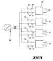
- the circuit shown in Fig. 7 initially has an AC voltage generator 22, the one generated in particular high-frequency AC voltage 26.
- Each connector 27 for transmitting the operating voltage is a power limiter in the form of a pair of capacitors 23, 24 upstream. It is in each of the two lines of the supply voltage the capacitor 23, 24 switched.
- the height of the connector 27 to be transferred is by the Capacitance of the pair of capacitors 23, 24 determined.
- the Performance is so limited that when you pull the Card on the connector 27 to no essential Sparking is coming.
- the power limit can also can be achieved by a coil.
- There is a circuit 25 for the card Signal evaluation of the channel The assigned to channel 25 Signal is also limited in performance Signal decoupling connection 28 to an analog signal line 6 given or comes from such a signal line 6.
- FIG. 8 shows a power limiting circuit, by means of which one of a high frequency alternator 26 generated AC voltage in a power-limited DC voltage is transferred. For this is used in the AC circuit Capacitor 29, which sits in front of a rectifier 30. A smoothing capacitor is located behind the rectifier 30 31 and a large number of Zener diodes 32.
- the module carrier with the reference number 18 4 assigned core halves shown.
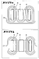
- the primary winding 20 can be used as a conductor track on the module carrier 4 forming circuit board be formed and each semicircular in the form of half-windings 20 ' middle core thigh surrounded.
- the two lines the operating voltage each form a half-winding 20 ', with the two half-windings 20' lying opposite one another.
- the individual half-windings 20 ' lie in rows next to each other in such a way that those in the row last half-windings 20 '' connected together are.
- the AC operating voltage about 1 volt.
- the Zener diodes shown in Figures 8 and 9 can also be done by adding a power transistor be supplemented.
- the signal converter according to the invention generates only low surface temperatures on the Components so that it is in the hazardous area can be arranged immediately. Because of the Reactive resistances are the thermal power losses reduced. As a result of the configuration according to the invention it is ensured that removal and attachment of the individual modules 5 can be done without sparking. It is irrelevant whether on the modules 5 themselves Circuits 13 are arranged or whether the modules only Plug parts are and via a cable connection are connected to circuit carriers.
- the novelty of the device according to the invention is that the divisible transformer makes it spark-free Plug connection is guaranteed and a current limit in the AC circuit through reactive resistors is achieved, which of capacitors or of coils can be formed. In this resistance network can have both complex and real resistances his. It is also important that a common Energy transfer takes place via the module carrier, with all primary coils either in parallel or in series be switched. The primary circles can be used as a planar coil be realized on the module carrier.
- the primary winding can be inserted separately two independent effects working primary coils exist.
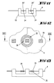
- FIG 11 is a first primary winding with the reference number 20 'shown, which consists of a planar coil on a Board side of the carrier 4 is made.
- On the back side There is another planar coil on this board 34, which belongs to the second power supply.
- a planar coil 35 surrounds spirally the middle leg of the core 18. By a Via 36 sits on planar coil 35 the opposite side of the board.
- each primary winding 20 Ballast element 37 upstream.
- these ballasts 37 can be switches, for example a reed switch.
- the one to be inserted into the plug contact Functional unit 5 can be the reed switch have actuating magnets so that when plugged in Functional unit 5 of the switch 37 closes, so that the coil 20 can be energized with alternating current.
- the function carrier 5 a Magnets 40 carries the 5 in when the module immediate neighborhood lies to a throttle 37, which forms the ballast element 37.
- the throttle 37 may have a core made of a material which can be driven into magnetic saturation. At Normal operation, this choke can be used as a current limit be used.
- Another alternative is one provided such control inductance. This is in Fig. 16 shown.
- the throttle 37 has one Core 39 with a gap. A section can be placed in this gap the functional unit 5 protrude. this section can carry a planar coil 41 that is shorted is.
- the voltage supply 9 consists of a Power supply 30, which provides a DC voltage, the is voltage limited by means of Zener diodes 32. about an inverter 26 becomes a trapezoidal AC voltage generated with a frequency of approx. 200 kHz. This alternating voltage is transferred via a jumper Conductor tracks of the module carrier 4 supplied.
- a plurality of primary windings 20 of the separable transformer halves On the Module carriers 4 are connected in parallel (cf. 14) a plurality of primary windings 20 of the separable transformer halves. Everyone this primary winding 20 is a ballast element upstream.
- the secondary sides of the transformers form secondary single coils 19 ', a rectifier via a choke 44 30 are connected upstream, which rectifier 30 an individual and galvanically isolated power supply trains for a circuit 25.
- the primary windings 20 are connected in series.
- the Rectifier 30 is followed by a current limit 42.
- the current limit 42 is an inverter 26 subordinate. Is located behind the inverter 26 a current regulator 43 to control the current in the AC circuit on the module carrier 4 readjust so that always enough current through the primary windings 20 flows, regardless of how many modules 5 are attached are. In this circuit it is provided that at least a minimum current flows through a secondary coil.
- FIG 19 shows a circuit example of one of two redundant power supplies existing power supply.
- Each transmitter half assigned to the module carrier 4 has two galvanically isolated primary coils 20 which are each connected to a power supply 9.
- the two primary voltages can be phase locked, so that the Add the effect of both primary windings.
- the amplitudes the primary voltages can, but do not have to be the same size.
- the phase angles of both primary voltages can be shifted against each other so that subtract the effects. If, for example, a power supply works incorrectly and delivers full performance, for example, can the second, properly working power supply Compensate for excess performance. This is also coming explosion protection.
- Both primary and Secondary windings can be designed as a planar coil his.
- the primary voltage applied can be sinusoidal. On Operation with triangular or trapezoidal or rectangular voltages is also conceivable.
- the individual impulses can - As shown in Fig. 22 - Key gaps or themselves have changing pulse / pause ratios. In particular can be provided that - as shown in Fig. 21 - the one power supply the positive half wave and the other power supply the negative phase-shifted Deliver half wave.
- the ballast element 37 is a property of the magnetic plug contact integrated (Fig. 23).
- the magnetic plug contact can also be used as in Figure 16 be formed. In this version it does not consist of a divisible transformer that follows closing has a smaller air gap than in open state.
- the magnetic plug contact exists then from a transformer with a constant air gap.
- Gap is a part of the module board 5, a secondary winding in the form of a planar coil when inserted of the module.
- the planar coil 41 not a short-circuited coil, but the Secondary coil 19.
- capacitors as reactive resistors for current limitation can be connected in parallel.
- FIG. 23 shows schematically a development of a voltage supply for one module.
- the supply voltage line on the module carrier 4 are for each slot of a module 5 leads switched for power supply of the respective module 5.
- the performance is over electrical contacts supplied to the module 5, these electrical contacts released when removing the module become. Sparking when removing the module plug-in card 5 is to be avoided individually before Plug contact switched a throttle 37. After that you can the throttle both in one of the two utilities, as well as switched in both supply lines be (Fig. 24).
- the supply voltage is in the Embodiment a square wave voltage, so that current flowing through the choke is a triangular shape has (Fig. 16).
- Fig. 26 shows an embodiment of such Throttle 37.
- the throttle has one of two E-shaped core halves 39 existing core.
- the two middle core legs are at a distance from each other and form an air gap.
- the two outer core legs touch each other. All three core legs protrude through openings 45 of the circuit board of the module carrier.
- Only at the outer legs of the core 39 are the coil windings 38 the throttle.
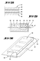
- the coil 38 is one Planar coil and is spaced apart by two Traces formed.
- the circuit board 47 has a total of three insulating layers 48 (Fig. 28). These form two outer ones Insulating layers, each with a thickness of 1 mm and a middle insulating layer with a thickness of 1/2 mm. Between these insulating layers, the epoxy there are conductor tracks 46.
- the first core halves 39 are assembled during assembly Glue 51 glued to the board so that the Leg of the core halves through the openings 45 of the Stick the board through (Fig. 29). Then the rear core halves 39 against the end faces 52 the outer leg glued. A fixation takes place through a U-shaped bar 49 that has a variety of cores 39 placed one behind the other in rows becomes. There is one on each side of the circuit board 47 such U-shaped bar 49. At both ends are the strips 49 with each other by means of fastening pins 50 connected, with the mounting pins through protrude through the board (Fig. 30).
- FIG. 31 schematically shows a transformer, which For example, on a circuit board of module 5 or the module carrier 4 or the power supply can be installed.
- the carrier is the core 55 of the transformer the board itself.
- the primary coil 54 and the secondary coil 56 are also here again formed by conductor tracks of the board.
- This transformer has not only the function, the secondary side to be galvanically separated from the primary side or transform the primary voltage to a secondary voltage.
- This transformer also has the function a secondary or primary throttle.
- this transformer in the in Fig. 17 or also 18 shown on a module 5 used.
- the transformer is used to power the Module.
- the core which is composed of two core halves has an essentially rectangular ring shape, the narrow legs 55 'of the core 55 of the Primary winding 54 and the secondary winding 56 assigned are.
- the longitudinal legs 55 '' connect the two the legs 55 'associated with the windings 55, 56.
- the Width B i.e. the distance between the two in the center of the coils 54, 56 lying leg 55 'is preferred greater than the height H, the distance between the two other leg 55 ''.
- This form of transformer core and the coil arrangement has the consequence that the in the equivalent circuit shown with 54 'and 56' parasitic Inductors become relatively large and so Have the effect of a throttle.
- Fig. 33 shows an embodiment in which the primary coil 54 and Secondary coil 56 do not overlap each other. Possible, but an overlap is not currently preferred the primary coil 54 with the secondary coil 56.
- the leakage inductance can range between 4 and 10% of the total inductance. One is preferred Leakage inductance of 4%. But it can also be larger be as 10%.
- FIG. 34 shows a circuit in which a 300 kHz square wave voltage via a choke 37 and subsequent plug contacts on Module 5 is transmitted.
- the plug contacts lead to Primary side of a transmitter, as shown in FIG. 33 is shown.
- the choke inductance shown there with 56 ' is a parasitic inductance and will caused by the magnetic shunt of the consisting of windings 54 and 56 transformer.
- a rectifier 30 connected to a filter capacitor 31 for providing an output DC voltage, which is present at the output terminals.
- the module carrier 4 is supplied with voltage preferably by two redundant power supplies 9 (Fig. 34).
- Each power supply 9 can be designed as a plug-in card and is therefore interchangeable.
- the redundancy of the two power supplies 9 has the consequence that an exchange of Power supplies can be done during operation.
- the Exchange of network cards should be spark-free.
- the power is transferred from Network card 9 on the module carrier 4 also in the way of a separate transformer, the primary winding 59 sits on the network card 9 and its secondary winding 57 sits on the module carrier 4. To design a such transformer is based on Figure 4 and related description referenced.
- a switch 58 On the module carrier 4 are the two secondary windings 57 connected in parallel to each other, however with the interposition of a switch 58 (Fig. 35).
- This switch 58 is only closed when in a voltage is induced in the secondary coil 57 or when the network card 9 is inserted and the primary coil 59 is energized '.
- Circuit example sits on the power supply 9 in The primary coil is connected in series with the primary coil 59 of an auxiliary transformer 60.
- the connections of the secondary coil this auxiliary transformer 60 are about conductive plug connections on a rectifier of the Transfer module carrier. Sitting behind the rectifier a relay 61 which operates the switch 58.
- the Auxiliary transformer 60 is designed to be very delivers little power, so when loosening the conductive Contacts to module carrier 4 no sparks arise. Becomes the connection is released, the relay 61, the switch 58 opens and the coil 57 is open. Also the Auxiliary transformer can be used as a separable transformer be trained.
- connection terminal 63 which are in the explosion-protected area.
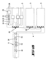
- a power supply line runs parallel to the data bus, which is fed by a power supply 9.
- the connection terminal 63 engages from this power supply line the operating voltage.
- the decoupled Energy is passed through a choke 44. So that out the connection terminal 63 a throttled AC voltage can be coupled out. This is due to one Plug connector on which a plug of a field device 3 can be plugged on.
- the configuration of the throttle shown in FIG. 37 44 show FIGS. 38 and 39.
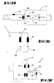
- the choke 44 shown is a capacitive one Throttle.
- the capacitors can be such Show value that the reactance between 50 and 1000 ohms.
- Capacitors for example, come as capacitors between 1 nF and 10 nF for an AC voltage between 200 kHz and 300 kHz.
- the throttle 44 shown in FIG. 39 has one Coil 33. However, this can also be provided as an alternative be that a further coil 33 switched on in the other operating voltage line is.
- the inductances of the coils are preferably between 1 and 10 ⁇ H.
- a reactance can be here be between 1 and 20 ohms.
- the supply voltage is preferably between 20 and 30 volts.
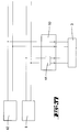
- 40 is a power supply unit according to the invention shown how to supply an explosion-proof Functional unit serves. The extraction of energy takes place here via the coil 33.
- FIG. 42 shows a Power supply according to Figures 40 or 41, as with a Connection terminal 63 is connected.
- the connection terminal 63 is line-connected to a field device 3 and supplied the field device 3 with that provided by the power supply unit 9 Operating voltage or ensures data exchange between the field device 3 and an evaluation unit 62.
- the power supply 9 can be outside of the explosion-proof Area 8 are.
- connection terminals 63 In the circuit example shown in Fig. 43 there is a switch box 2 together with a Master computer 1 outside the explosion-protected area 8. There are a large number in switch box 2 of connection terminals 63. For the sake of clarity only a connection terminal 63 is shown.
- the Connection terminals can be on a separate PCB be built. But it is also possible that the connection terminals 63 on a common board sit.
- the connection terminal 63 is a choke 44 assigned as shown in Figures 38 and 39, respectively.
- the choke 44 is powered by a power supply 9.
- the energy throttled as a result of throttle 44 is coupled out to a field device 3.
- the field device 3 lies in the explosion-protected area.
Landscapes
- Engineering & Computer Science (AREA)
- Computer Networks & Wireless Communication (AREA)
- Power Engineering (AREA)
- Dc-Dc Converters (AREA)
- Remote Monitoring And Control Of Power-Distribution Networks (AREA)
- Rectifiers (AREA)
Applications Claiming Priority (4)
| Application Number | Priority Date | Filing Date | Title |
|---|---|---|---|
| DE19859715 | 1998-12-23 | ||
| DE19859715 | 1998-12-23 | ||
| DE19949649 | 1999-10-14 | ||
| DE19949649A DE19949649A1 (de) | 1998-12-23 | 1999-10-14 | Energieversorgung für explosionsgeschützte elektronische Funktionseinheiten |
Publications (3)
| Publication Number | Publication Date |
|---|---|
| EP1014531A2 true EP1014531A2 (fr) | 2000-06-28 |
| EP1014531A3 EP1014531A3 (fr) | 2001-08-01 |
| EP1014531B1 EP1014531B1 (fr) | 2010-03-10 |
Family
ID=26051001
Family Applications (1)
| Application Number | Title | Priority Date | Filing Date |
|---|---|---|---|
| EP99125477A Expired - Lifetime EP1014531B1 (fr) | 1998-12-23 | 1999-12-21 | Appareil d'alimentation en énergie électrique pour composants électroniques anti-déflagrant |
Country Status (1)
| Country | Link |
|---|---|
| EP (1) | EP1014531B1 (fr) |
Cited By (9)
| Publication number | Priority date | Publication date | Assignee | Title |
|---|---|---|---|---|
| WO2003085797A3 (fr) * | 2002-04-06 | 2004-02-05 | Wampfler Ag | Procede de transmission inductive d'energie electrique |
| DE202013008747U1 (de) | 2013-10-01 | 2013-12-12 | Abb Technology Ag | Energieversorgungseinrichtung für explosionsgeschützte elektronische Funktionseinheiten |
| DE202013009502U1 (de) | 2013-10-24 | 2014-01-09 | Abb Technology Ag | Energieversorgungseinrichtung für explosionsgeschützte elektronische Funktionseinheiten |
| DE202013009990U1 (de) | 2013-11-04 | 2014-01-16 | Abb Technology Ag | Energieversorgungseinrichtung für explosionsgeschützte elektronische Funktionseinheiten |
| DE202014010424U1 (de) | 2014-06-20 | 2015-09-03 | Abb Technology Ag | Energieversorgungseinrichtung für explosionsgeschützte elektronische Funktionseinheiten |
| EP3089342B1 (fr) * | 2015-04-28 | 2021-10-20 | Foxboro Eckardt Gmbh | Appareil de terrain à sécurité intrinsèque avec circuit de conversion de tension et commande a retroaction |
| EP4307058A1 (fr) | 2022-07-15 | 2024-01-17 | Turck Holding GmbH | Station destinée à être utilisée dans un réseau de terrain entre un ou plusieurs appareils de terrain et une unité centrale ainsi que module de commutation enfichable amovible dans un support de module |
| EP4078302B1 (fr) | 2019-12-19 | 2024-11-06 | PHOENIX CONTACT GmbH & Co. KG | Appareil d'échange de signaux entre un dispositif de commande et des dispositifs de terrain |
| PL444965A1 (pl) * | 2023-05-19 | 2024-11-25 | Instytut Techniki Górniczej Komag | Bezprzewodowy układ przesyłu energii w wykonaniu przeciwwybuchowym |
Family Cites Families (5)
| Publication number | Priority date | Publication date | Assignee | Title |
|---|---|---|---|---|
| ZA733581B (en) * | 1972-07-27 | 1974-04-24 | Gen Electric | Automatic voltage control for an electric precipitator |
| US4342061A (en) * | 1981-03-04 | 1982-07-27 | Frank W. Murphy Manufacturer, Inc. | Voltage reduction safety circuit |
| JPH0747957Y2 (ja) * | 1987-03-31 | 1995-11-01 | トツパン・ム−ア株式会社 | 非接触式電力供給装置 |
| US5301096A (en) * | 1991-09-27 | 1994-04-05 | Electric Power Research Institute | Submersible contactless power delivery system |
| DE69535873D1 (de) * | 1994-07-13 | 2008-12-04 | Auckland Uniservices Ltd | Induktiv gespeiste Beleuchtung |
-
1999
- 1999-12-21 EP EP99125477A patent/EP1014531B1/fr not_active Expired - Lifetime
Cited By (16)
| Publication number | Priority date | Publication date | Assignee | Title |
|---|---|---|---|---|
| WO2003085797A3 (fr) * | 2002-04-06 | 2004-02-05 | Wampfler Ag | Procede de transmission inductive d'energie electrique |
| CN104518523B (zh) * | 2013-10-01 | 2018-08-17 | Abb瑞士股份有限公司 | 用于防爆的电子功能单元的能量供给装置 |
| DE202013008747U1 (de) | 2013-10-01 | 2013-12-12 | Abb Technology Ag | Energieversorgungseinrichtung für explosionsgeschützte elektronische Funktionseinheiten |
| EP2858203A1 (fr) | 2013-10-01 | 2015-04-08 | ABB Technology AG | Dispositif d'alimentation en énergie pour des unités de fonctionnement électroniques protégées contre les explosions |
| CN104518523A (zh) * | 2013-10-01 | 2015-04-15 | Abb技术股份公司 | 用于防爆的电子功能单元的能量供给装置 |
| US9396864B2 (en) | 2013-10-01 | 2016-07-19 | Abb Technology Ag | Energy supply device for explosion-proof electronic functional units |
| DE202013009502U1 (de) | 2013-10-24 | 2014-01-09 | Abb Technology Ag | Energieversorgungseinrichtung für explosionsgeschützte elektronische Funktionseinheiten |
| EP2871647A1 (fr) | 2013-10-24 | 2015-05-13 | ABB Technology AG | Dispositif d'alimentation en énergie pour des unités de fonctionnement électroniques protégées contre les explosions |
| DE202013009990U1 (de) | 2013-11-04 | 2014-01-16 | Abb Technology Ag | Energieversorgungseinrichtung für explosionsgeschützte elektronische Funktionseinheiten |
| EP2871648A1 (fr) | 2013-11-04 | 2015-05-13 | ABB Technology AG | Dispositif d'alimentation en énergie pour des unités de fonctionnement électroniques protégées contre les explosions |
| DE202014010424U1 (de) | 2014-06-20 | 2015-09-03 | Abb Technology Ag | Energieversorgungseinrichtung für explosionsgeschützte elektronische Funktionseinheiten |
| EP3089342B1 (fr) * | 2015-04-28 | 2021-10-20 | Foxboro Eckardt Gmbh | Appareil de terrain à sécurité intrinsèque avec circuit de conversion de tension et commande a retroaction |
| EP4078302B1 (fr) | 2019-12-19 | 2024-11-06 | PHOENIX CONTACT GmbH & Co. KG | Appareil d'échange de signaux entre un dispositif de commande et des dispositifs de terrain |
| EP4307058A1 (fr) | 2022-07-15 | 2024-01-17 | Turck Holding GmbH | Station destinée à être utilisée dans un réseau de terrain entre un ou plusieurs appareils de terrain et une unité centrale ainsi que module de commutation enfichable amovible dans un support de module |
| DE102022117693A1 (de) | 2022-07-15 | 2024-01-18 | Turck Holding Gmbh | Station zum Einsatz in einem Feldnetz zwischen einem oder mehreren Feldgeräten und einer Zentraleinheit sowie in einen Modulträger auswechselbar einsteckbares Switch-Modul |
| PL444965A1 (pl) * | 2023-05-19 | 2024-11-25 | Instytut Techniki Górniczej Komag | Bezprzewodowy układ przesyłu energii w wykonaniu przeciwwybuchowym |
Also Published As
| Publication number | Publication date |
|---|---|
| EP1014531B1 (fr) | 2010-03-10 |
| EP1014531A3 (fr) | 2001-08-01 |
Similar Documents
| Publication | Publication Date | Title |
|---|---|---|
| EP1275208B1 (fr) | Dispositif de transmission sans contact de signaux electriques ou d'energie electrique | |
| EP2803143B1 (fr) | Dispositif d'alimentation en énergie inductive | |
| DE2409884B2 (de) | Stromversorgungsteil für einen elektronischen Rundsteuerempfänger | |
| DE10026175C2 (de) | Anordnung zur kontaktlosen Übertragung elektrischer Signale bzw. Energie zwischen einer feststehenden Einheit und mehreren ortsveränderlichen Einheiten | |
| DE10084799T5 (de) | Universelle eigensichere Schaltstromversorgung | |
| DE102012110173A1 (de) | Modulares Elektroniksystem und Busteilnehmer | |
| DE102008044429B4 (de) | Energieumwandlungssystem für ein Kraftfahrzeug | |
| EP1014531B1 (fr) | Appareil d'alimentation en énergie électrique pour composants électroniques anti-déflagrant | |
| DE19640367A1 (de) | Leitungslose Energie- und Datenübertragung für ein modulares Peripherie-System | |
| EP1285501A1 (fr) | Dispositif de couplage | |
| EP3169891B1 (fr) | Schéma d'enroulement pour un transformateur d'un convertisseur élévateur de tension et système d'allumage servant à alimenter en énergie électrique un éclateur d'un moteur à combustion interne | |
| DE19949649A1 (de) | Energieversorgung für explosionsgeschützte elektronische Funktionseinheiten | |
| DE3508267A1 (de) | Ablenk-netzteil-konzept fuer fersehgeraete | |
| DE102016202922A1 (de) | Energieübertrager und Verfahren zum Betreiben eines Energieübertragers | |
| DE4425250C1 (de) | Anordnung zur potentialgetrennten Energie- und Datenübertragung über eine Zweidrahtbusleitung | |
| WO2016046023A1 (fr) | Dispositif à valeur de capacité ajustable permettant d'accorder un système oscillant, système oscillant et système de transmission d'énergie | |
| DE102014102936A1 (de) | Elektronische Baugruppe mit interner Nahfeldkommunikation | |
| DE4436592A1 (de) | Galvanisch getrennte Daten- und Energieübertragung | |
| EP1252698B1 (fr) | Systeme de distribution de courant presentant une resistance aux courts-circuits inherente | |
| DE102017217198A1 (de) | Adaptervorrichtung für eine mindestens zwei Spulen aufweisende induktive Ladeanordnung und Verfahren. | |
| DE2826897B1 (de) | Schaltungsanordnung zur erdfreien UEbertragung von Signalen ueber Trennstellen in Fernmeldeanlagen | |
| DE19951114A1 (de) | Lampenansteuerschaltung | |
| DE3511967A1 (de) | Einrichtung zur kontrolle von elektrischen verbrauchern in kraftfahrzeugen | |
| WO2019193095A1 (fr) | Dispositif électronique d'entrée/sortie pour la transmission de signaux, de données et/ou de puissance avec isolation galvanique | |
| EP4531260A1 (fr) | Convertisseur de tension et procédé de fonctionnement d'un convertisseur de tension |
Legal Events
| Date | Code | Title | Description |
|---|---|---|---|
| PUAI | Public reference made under article 153(3) epc to a published international application that has entered the european phase |
Free format text: ORIGINAL CODE: 0009012 |
|
| AK | Designated contracting states |
Kind code of ref document: A2 Designated state(s): AT BE CH CY DE DK ES FI FR GB GR IE IT LI LU MC NL PT SE |
|
| AX | Request for extension of the european patent |
Free format text: AL;LT;LV;MK;RO;SI |
|
| PUAL | Search report despatched |
Free format text: ORIGINAL CODE: 0009013 |
|
| AK | Designated contracting states |
Kind code of ref document: A3 Designated state(s): AT BE CH CY DE DK ES FI FR GB GR IE IT LI LU MC NL PT SE |
|
| AX | Request for extension of the european patent |
Free format text: AL;LT;LV;MK;RO;SI |
|
| 17P | Request for examination filed |
Effective date: 20011123 |
|
| AKX | Designation fees paid |
Free format text: AT BE CH CY DE DK ES FI FR GB GR IE IT LI LU MC NL PT SE |
|
| AXX | Extension fees paid |
Free format text: AL PAYMENT 20011123;LT PAYMENT 20011123;LV PAYMENT 20011123;MK PAYMENT 20011123;RO PAYMENT 20011123;SI PAYMENT 20011123 |
|
| 17Q | First examination report despatched |
Effective date: 20081007 |
|
| GRAP | Despatch of communication of intention to grant a patent |
Free format text: ORIGINAL CODE: EPIDOSNIGR1 |
|
| RTI1 | Title (correction) |
Free format text: POWER SUPPLY APPARATUS FOR EXPLOSION-PROOF ELECTRONIC COMPONENTS |
|
| GRAS | Grant fee paid |
Free format text: ORIGINAL CODE: EPIDOSNIGR3 |
|
| GRAA | (expected) grant |
Free format text: ORIGINAL CODE: 0009210 |
|
| AK | Designated contracting states |
Kind code of ref document: B1 Designated state(s): AT BE CH CY DE DK ES FI FR GB GR IE IT LI LU MC NL PT SE |
|
| AX | Request for extension of the european patent |
Extension state: AL LT LV MK RO SI |
|
| REG | Reference to a national code |
Ref country code: GB Ref legal event code: FG4D Free format text: NOT ENGLISH |
|
| REG | Reference to a national code |
Ref country code: CH Ref legal event code: EP |
|
| REG | Reference to a national code |
Ref country code: IE Ref legal event code: FG4D |
|
| REF | Corresponds to: |
Ref document number: 59915140 Country of ref document: DE Date of ref document: 20100422 Kind code of ref document: P |
|
| REG | Reference to a national code |
Ref country code: CH Ref legal event code: NV Representative=s name: R. A. EGLI & CO. PATENTANWAELTE |
|
| REG | Reference to a national code |
Ref country code: ES Ref legal event code: FG2A Ref document number: 2340744 Country of ref document: ES Kind code of ref document: T3 |
|
| REG | Reference to a national code |
Ref country code: NL Ref legal event code: VDEP Effective date: 20100310 |
|
| LTIE | Lt: invalidation of european patent or patent extension |
Effective date: 20100310 |
|
| PG25 | Lapsed in a contracting state [announced via postgrant information from national office to epo] |
Ref country code: FI Free format text: LAPSE BECAUSE OF FAILURE TO SUBMIT A TRANSLATION OF THE DESCRIPTION OR TO PAY THE FEE WITHIN THE PRESCRIBED TIME-LIMIT Effective date: 20100310 |
|
| REG | Reference to a national code |
Ref country code: IE Ref legal event code: FD4D |
|
| PG25 | Lapsed in a contracting state [announced via postgrant information from national office to epo] |
Ref country code: SE Free format text: LAPSE BECAUSE OF FAILURE TO SUBMIT A TRANSLATION OF THE DESCRIPTION OR TO PAY THE FEE WITHIN THE PRESCRIBED TIME-LIMIT Effective date: 20100310 Ref country code: NL Free format text: LAPSE BECAUSE OF FAILURE TO SUBMIT A TRANSLATION OF THE DESCRIPTION OR TO PAY THE FEE WITHIN THE PRESCRIBED TIME-LIMIT Effective date: 20100310 Ref country code: GR Free format text: LAPSE BECAUSE OF FAILURE TO SUBMIT A TRANSLATION OF THE DESCRIPTION OR TO PAY THE FEE WITHIN THE PRESCRIBED TIME-LIMIT Effective date: 20100611 Ref country code: CY Free format text: LAPSE BECAUSE OF FAILURE TO SUBMIT A TRANSLATION OF THE DESCRIPTION OR TO PAY THE FEE WITHIN THE PRESCRIBED TIME-LIMIT Effective date: 20100310 |
|
| PLBE | No opposition filed within time limit |
Free format text: ORIGINAL CODE: 0009261 |
|
| STAA | Information on the status of an ep patent application or granted ep patent |
Free format text: STATUS: NO OPPOSITION FILED WITHIN TIME LIMIT |
|
| PG25 | Lapsed in a contracting state [announced via postgrant information from national office to epo] |
Ref country code: PT Free format text: LAPSE BECAUSE OF FAILURE TO SUBMIT A TRANSLATION OF THE DESCRIPTION OR TO PAY THE FEE WITHIN THE PRESCRIBED TIME-LIMIT Effective date: 20100712 Ref country code: IE Free format text: LAPSE BECAUSE OF FAILURE TO SUBMIT A TRANSLATION OF THE DESCRIPTION OR TO PAY THE FEE WITHIN THE PRESCRIBED TIME-LIMIT Effective date: 20100310 Ref country code: DK Free format text: LAPSE BECAUSE OF FAILURE TO SUBMIT A TRANSLATION OF THE DESCRIPTION OR TO PAY THE FEE WITHIN THE PRESCRIBED TIME-LIMIT Effective date: 20100310 |
|
| 26N | No opposition filed |
Effective date: 20101213 |
|
| PG25 | Lapsed in a contracting state [announced via postgrant information from national office to epo] |
Ref country code: IT Free format text: LAPSE BECAUSE OF FAILURE TO SUBMIT A TRANSLATION OF THE DESCRIPTION OR TO PAY THE FEE WITHIN THE PRESCRIBED TIME-LIMIT Effective date: 20100310 |
|
| BERE | Be: lapsed |
Owner name: HANS TURCK G.M.B.H. & CO. KG Effective date: 20101231 |
|
| PG25 | Lapsed in a contracting state [announced via postgrant information from national office to epo] |
Ref country code: MC Free format text: LAPSE BECAUSE OF NON-PAYMENT OF DUE FEES Effective date: 20101231 |
|
| REG | Reference to a national code |
Ref country code: CH Ref legal event code: PL |
|
| GBPC | Gb: european patent ceased through non-payment of renewal fee |
Effective date: 20101221 |
|
| REG | Reference to a national code |
Ref country code: FR Ref legal event code: ST Effective date: 20110831 |
|
| PG25 | Lapsed in a contracting state [announced via postgrant information from national office to epo] |
Ref country code: BE Free format text: LAPSE BECAUSE OF NON-PAYMENT OF DUE FEES Effective date: 20101231 |
|
| PG25 | Lapsed in a contracting state [announced via postgrant information from national office to epo] |
Ref country code: FR Free format text: LAPSE BECAUSE OF NON-PAYMENT OF DUE FEES Effective date: 20110103 Ref country code: LI Free format text: LAPSE BECAUSE OF NON-PAYMENT OF DUE FEES Effective date: 20101231 Ref country code: CH Free format text: LAPSE BECAUSE OF NON-PAYMENT OF DUE FEES Effective date: 20101231 |
|
| PG25 | Lapsed in a contracting state [announced via postgrant information from national office to epo] |
Ref country code: GB Free format text: LAPSE BECAUSE OF NON-PAYMENT OF DUE FEES Effective date: 20101221 |
|
| REG | Reference to a national code |
Ref country code: ES Ref legal event code: FD2A Effective date: 20120206 |
|
| PG25 | Lapsed in a contracting state [announced via postgrant information from national office to epo] |
Ref country code: AT Free format text: LAPSE BECAUSE OF NON-PAYMENT OF DUE FEES Effective date: 20101221 |
|
| REG | Reference to a national code |
Ref country code: AT Ref legal event code: MM01 Ref document number: 460764 Country of ref document: AT Kind code of ref document: T Effective date: 20101221 |
|
| PG25 | Lapsed in a contracting state [announced via postgrant information from national office to epo] |
Ref country code: ES Free format text: LAPSE BECAUSE OF NON-PAYMENT OF DUE FEES Effective date: 20101222 |
|
| PG25 | Lapsed in a contracting state [announced via postgrant information from national office to epo] |
Ref country code: LU Free format text: LAPSE BECAUSE OF NON-PAYMENT OF DUE FEES Effective date: 20101221 |
|
| PGFP | Annual fee paid to national office [announced via postgrant information from national office to epo] |
Ref country code: DE Payment date: 20181207 Year of fee payment: 20 |
|
| REG | Reference to a national code |
Ref country code: DE Ref legal event code: R071 Ref document number: 59915140 Country of ref document: DE |