EP1014719A1 - Wiedergabe von fotografischen Bildern auf einem Fernsehschirm, wobei einen Videorecorder benutzt wird - Google Patents
Wiedergabe von fotografischen Bildern auf einem Fernsehschirm, wobei einen Videorecorder benutzt wird Download PDFInfo
- Publication number
- EP1014719A1 EP1014719A1 EP99420239A EP99420239A EP1014719A1 EP 1014719 A1 EP1014719 A1 EP 1014719A1 EP 99420239 A EP99420239 A EP 99420239A EP 99420239 A EP99420239 A EP 99420239A EP 1014719 A1 EP1014719 A1 EP 1014719A1
- Authority
- EP
- European Patent Office
- Prior art keywords
- cassette
- vcr
- strip
- film
- rotation
- Prior art date
- Legal status (The legal status is an assumption and is not a legal conclusion. Google has not performed a legal analysis and makes no representation as to the accuracy of the status listed.)
- Withdrawn
Links
Images

Classifications
-
- H—ELECTRICITY
- H04—ELECTRIC COMMUNICATION TECHNIQUE
- H04N—PICTORIAL COMMUNICATION, e.g. TELEVISION
- H04N1/00—Scanning, transmission or reproduction of documents or the like, e.g. facsimile transmission; Details thereof
- H04N1/00127—Connection or combination of a still picture apparatus with another apparatus, e.g. for storage, processing or transmission of still picture signals or of information associated with a still picture
- H04N1/00129—Connection or combination of a still picture apparatus with another apparatus, e.g. for storage, processing or transmission of still picture signals or of information associated with a still picture with a display device, e.g. CRT or LCD monitor
-
- H—ELECTRICITY
- H04—ELECTRIC COMMUNICATION TECHNIQUE
- H04N—PICTORIAL COMMUNICATION, e.g. TELEVISION
- H04N1/00—Scanning, transmission or reproduction of documents or the like, e.g. facsimile transmission; Details thereof
- H04N1/00127—Connection or combination of a still picture apparatus with another apparatus, e.g. for storage, processing or transmission of still picture signals or of information associated with a still picture
- H04N1/00281—Connection or combination of a still picture apparatus with another apparatus, e.g. for storage, processing or transmission of still picture signals or of information associated with a still picture with a telecommunication apparatus, e.g. a switched network of teleprinters for the distribution of text-based information, a selective call terminal
- H04N1/00283—Connection or combination of a still picture apparatus with another apparatus, e.g. for storage, processing or transmission of still picture signals or of information associated with a still picture with a telecommunication apparatus, e.g. a switched network of teleprinters for the distribution of text-based information, a selective call terminal with a television apparatus
-
- H—ELECTRICITY
- H04—ELECTRIC COMMUNICATION TECHNIQUE
- H04N—PICTORIAL COMMUNICATION, e.g. TELEVISION
- H04N1/00—Scanning, transmission or reproduction of documents or the like, e.g. facsimile transmission; Details thereof
- H04N1/04—Scanning arrangements, i.e. arrangements for the displacement of active reading or reproducing elements relative to the original or reproducing medium, or vice versa
- H04N1/19—Scanning arrangements, i.e. arrangements for the displacement of active reading or reproducing elements relative to the original or reproducing medium, or vice versa using multi-element arrays
- H04N1/195—Scanning arrangements, i.e. arrangements for the displacement of active reading or reproducing elements relative to the original or reproducing medium, or vice versa using multi-element arrays the array comprising a two-dimensional [2D] array
-
- H—ELECTRICITY
- H04—ELECTRIC COMMUNICATION TECHNIQUE
- H04N—PICTORIAL COMMUNICATION, e.g. TELEVISION
- H04N5/00—Details of television systems
- H04N5/76—Television signal recording
- H04N5/78—Television signal recording using magnetic recording
- H04N5/782—Television signal recording using magnetic recording on tape
-
- H—ELECTRICITY
- H04—ELECTRIC COMMUNICATION TECHNIQUE
- H04N—PICTORIAL COMMUNICATION, e.g. TELEVISION
- H04N2201/00—Indexing scheme relating to scanning, transmission or reproduction of documents or the like, and to details thereof
- H04N2201/04—Scanning arrangements
- H04N2201/0402—Arrangements not specific to a particular one of the scanning methods covered by groups H04N1/04 - H04N1/207
- H04N2201/0404—Scanning transparent media, e.g. photographic film
- H04N2201/0408—Scanning film strips or rolls
Definitions
- the invention relates to the display of photographs on a television screen and especially to a video cassette recorder (VCR), such as for example VHS ®, enabling the display by means of a conventional commercial VCR of photographs recorded on a strip of film wound on a spool or reel such as for example photographs in APS ® format.
- VCR video cassette recorder
- US Patent 5 025 331 describes a VCR that can receive two types of cassettes of different sizes.
- US Patent 5 280 400 describes a magnetic tape adapter cassette enabling a smaller size magnetic tape cassette to be inserted in a larger size magnetic tape cassette.
- US Patent 5 587 853 describes a VHS ® format adapter videocassette able to receive a smaller VHS-C ® videocassette.
- the invention offers to provide a small sized device, for example of the standard size of a VHS ® cassette.
- the invention further offers to provide a cheap device useable in commercial VCRs, for example VHS ® type.
- the device according to the invention can be inserted into a VCR and enable the display of images recorded on a strip of photographic film wound on a spool or reel.
- the device comprises: a) means to load a reel on which is wound a strip of photographic film having photographic images recorded thereon; b) transport means controlled by the operation of the VCR to unwind and rewind the strip of film wound on the reel and move this strip in an indexed way in relation to an analysis position; c) analysis means to provide a video signal of the image stored on the strip of film and located in front of the analysis position.
- the invention further aims at a new type of VCR adapted to receiving a cassette provided with a recognition means and connection means.
- the VCR comprising: a) a detector of the recognition means carried by the cassette; and b) a connection means for, when the cassette is introduced into the VCR, linking up the connection means of the cassette and those of the VCR to direct the control signals of the VCR to the cassette, the cassette comprising: a) means to receive a reel on which is wound a strip of photographic film having photographic images recorded thereon; b) transport means controlled by the operation of the VCR to unwind and rewind the strip of film wound on the reel and move this strip in an indexed way in relation to an analysis position; c) analysis means to provide a video signal of the image stored on the strip of film and located in front of the analysis position.
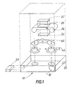
- Figure 1 represents a cut-away of the device according to the invention.
- FIG. 2 represents diagrammatically the various functions required in the device according to the invention.
- the type of film having been used for recording is identified by means of a switch 14 that shows whether the views were recorded on negative film or on positive film.
- the device 10 according to the invention also hereafter called the adapter cassette, is introduced into the VCR.
- the adapter cassette is provided with an electrical connecting means 16, such as for example a coaxial cable, leaving the VCR by the opening for loading cassettes and enabling the adapter cassette to be linked to the television set.
- the adapter cassette has the shape and dimensions of a VHS ® cassette and the VCR used is a VHS ® VCR.
- the external dimensions of the adapter cassette 10 have to satisfy certain dimensions and characteristics of standard NF EN 60774-1 relating to VHS videotape cassettes.
- the strip of film is contained in a cartridge that has the shape of an APS ® cartridge.
- the "Redbook" can be referred to which is also to be found on the Internet ® Kodak ® site.
- the output signal is transmitted to the television by a coaxial cable coming from the adapter cassette and leaving the VCR case by the opening for loading the cassettes in the VCR.
- VCRs are supplied with safety systems enabling the detection of various operational faults or anomalies due to the introduction of a defective cassette.
- Those skilled in the art will be able to allow for these safety systems to prevent stopping the operation of the VCR when an adapter cassette according to the invention is introduced and design a new type of VCR that can also be used to display, on a television screen, photographic views recorded on the films contained in APS ® type cartridges.
- the cassette and the VCR can in this case be adapted so that they are fitted with connection means.
- the connection means interact and the VCR can send control information directly to the adapter cassette.
- the video display information generated by the cassette can be sent automatically to the television by the existing liaison linking the VCR to the television.
- the adapter cassette 10 will allow for current safety systems used in actual VCRs to be able to be used directly by most potential users having a VHS ® type VCR. With VCRs, when they detect an operational anomaly, they go into a "standby" operational mode wherein the two spindles for driving the spools do not rotate.
- Conventional cassettes have a location on the lower panel into which, on introducing the cassette into the VCR, a light source solid with the VCR and supplied by the VCR penetrates; this location has to be conserved to prevent damage to the VCRs.
- the side panels of conventional cassettes each have an opening to permit a detector located inside the VCR to detect the start or end of the tape, which has a transparent leader, by the transmission of a light pencil coming from the source mentioned above.
- the light coming from the source should be prevented from exciting the sensors detecting the end of the tape, which would cause the VCR to stop.
- the adapter cassette will thus comprise a winding spool and an unwinding spool interlinked by a kinematic chain 64.
- the shape and dimensions of the spools will satisfy the relevant parts of the previously mentioned standard.
- an odd number of toothed wheels is used to drive the unwinding spool when the winding spool is rotating to prevent the stop of the VCR.
- one gear of the kinematic chain 64 used is provided with a mechanism for delaying the reversal of the direction of rotation by about one turn.
- the tape drive mechanism located inside the VCR, extracts the cassette tape by means of two arms to wind it on the reading capstan; the left arm is associated with a brake tensioner which, in the absence of tape prevents the rotation of the left spool and stops the VCR.
- the adapter cassette has to prevent the operation of this safety device. To achieve this, it is sufficient to immobilize the tensioner associated with the left arm for example with part of the adapter cassette that prevents the movement of this tensioner.
- the shape of the cassette shall thus be slightly modified compared with the previously mentioned standard.
- VHS cassettes which are not being used in a VCR
- an internal spool locking mechanism prevents unwanted unwinding of the tape.
- VCRs thus have, fixed on the chassis, a stud that penetrates via a hole in the cassette to unlock the internal spool locking mechanism.
- the adapter cassette shall thus be provided with the corresponding hole.
- the adapter cassette 10 comprises a reception module 18 for an APS cartridge to be displayed.
- This module has a loading slot 12 for an APS type cartridge.
- This module allows an APS type cartridge to be received in a set orientation.
- the magazine comprises a detection element 20 for the presence of a cartridge located inside the magazine.
- This element 20 extends beyond the volume described by the adapter cassette 10 when no cartridge is introduced in the loading slot 12.
- the element 20 is designed to prevent the introduction of the adapter cassette 10 in the VCR when the magazine is empty.
- the reception module 18 is associated with a transport module 22 for the film strip contained in the cartridge located in the loading slot 12.
- This module comprises a film guide 24 provided with an opening 26 and a receiving magazine 28 as well as a film drive motor (not shown).
- the opening 26 defines an analysis position.
- assemblies developed for various types of APS ® cameras can be used.
- the adapter cassette 10 is fitted with an analysis module 30 that essentially comprises an extended diffuse light source 32 to illuminate the image recorded on the strip of film 34 and a sensor 36, preferably CCD type bitmap, which enables the supply of an electrical signal representing the image.
- the signal is transformed into a digital signal.
- the analysis module 30 can be similar to that developed by the Eastman Kodak Company ® and used in the device "Kodak Advantix Film Drive FD 300" ®. This module also comprises the transport module 22 mentioned above.
- the adapter cassette 10 also comprises a module 38 for transforming the signal representing the image generated by the analysis device into video signal that can be used directly by the television and that is sent via the cable 16 mentioned above.
- the adapter cassette is fitted with a transformation circuit 38 adapted to the television standard used in the sale country of the adapter cassette.
- several separate electric signal transformation modules can also be planned whose operation will be triggered according to the position of a switch 40 arranged on the adapter cassette.
- the adapter cassette also comprises a control module 42 whose operation is controlled by the VCR remote control 60 by means of the rotation of the spools.
- This module comprises a sensor 46 that enables detection of the direction of rotation of the spools and estimation of their speed of rotation. The operation of this module will be described later.
- the cassette comprises an electronic card 48 controlling the various modules and a power supply either internal by independent battery 50, or external 52 that can come to the adapter cassette by a wire penetrating in the VCR through the cassette loading opening.
- a switch 54 allows the power supply mode of the adapter cassette 10 to be selected; clearly this switching can also be effected automatically.
- the control module 42 whose operation is controlled by the VCR remote control 60 by means of the rotation of the spools will now be described in more detail. It has been noticed that the speed of rotation of the spools is a function of the VCR's mode of operation.
- VCRs usually having a standby or pause mode in which the right and left spools do not rotate, a play mode in which the right and left spools rotate at an initial speed in an initial direction corresponding to the tape advance, a fast forward play mode in which the right and left spools rotate at a second speed higher than the initial speed of rotation in the initial direction of rotation, a fast rewind play mode in which the right and left spools rotate at the second speed in a second direction the reverse of the initial direction of rotation, a fast forward mode in which the right and left spools rotate at a third speed higher than the second speed of rotation and in the initial direction of rotation and a fast rewind mode in which the right and left spools rotate at the third speed higher than the second speed of rotation and in the second direction of rotation, as well as a cassette eject mode in which the left spool rotates in the second direction of rotation to tension the tape and come to a stop as the right spool is braked.
- VCR operating modes are remotely controlled by a remote control 60 that has a ⁇ button for the play mode, a ⁇ button for the pause or standby mode, a ⁇ button for the fast forward play mode when the VCR is in play mode and fast forward mode when the VCR is in standby or fast rewind mode, a ⁇ button for the fast rewind play mode when the VCR is in play (normal or fast) and fast rewind mode when the VCR is in standby or fast forward mode.
- the eject mode is triggered by a button located on the VCR case.
- the VCR goes into standby mode when the transparent leader allows the light to pass to the previously mentioned detector.
- the control module 42 of the adapter cassette uses the various speeds of rotation of the spools to control the various step involved in displaying the images carried by the strip of film 34 contained in the APS cartridge inserted in the slot 12 of the adapter cassette 10.
- the VCR After having introduced an adapter cassette 10 in the VCR, the VCR goes into standby mode, the spools do not rotate. A press on one of the buttons of the remote control causes the spools to rotate at a set speed.
- the kinematic chain 64 interlinking the spools supplies the same speed and in the same direction to both spools. Thus it is sufficient to detect the direction of rotation and assess the speed of rotation to control the various modes of operation.
- the sensor 46 thus comprises two similar detection devices. Each detection device reads a repetitive design of alternating black and white fields arranged on a spool, the black fields having a different width than the white fields to supply a signal close to a pulse.
- the fields scanned by one of the detection devices are slightly offset from the fields scanned by the other detection device to enable detection of the direction of rotation.
- the number of fields scanned by one sensor during a given interval of time allowing the speed of rotation to be assessed.
- the detection signal is only transmitted to the control card when the speed of rotation of the spools changes.
- the ⁇ button orders the rotation of the spools at an initial transport speed which is detected by the sensor 46 previously mentioned.
- An order to move the strip 34 of film wound in the APS cartridge is sent to the transport module 22 of the strip by an electronic card 48 so that a first image is indexed in front of the opening 26 made in the guide using for example the detection of the perforations 56.
- the analysis module is excited and the image sensor 36, preferably bitmap, supplies the analogue signal representing the image to the transformation module.
- This analogue signal is transformed into a video signal, which is sent to the television by the electrical connecting means 16 with a view to displaying the corresponding image.
- the VCR interrupts the rotation of the spools, a signal is sent to the electronic control card 48 which stops the display of the image on the television screen.
- the ⁇ button has to pressed to stop the rotation of the spools, and the ⁇ button is pressed again which makes the spools rotate at the initial transport speed. The previously described cycle is then repeated.
- the ⁇ button is pressed when the VCR is in standby mode, the spools are nct rotating, the signal sent to the control card does not cause any action on the part of any of the modules. However, if the ⁇ button is pressed when the VCR is in play mode and the spools rotate at the initial speed, the signal coming to the video signal generating module is changed so as to display an image rotated +90°. If the ⁇ button is pressed when the VCR is in play mode and the spools rotate at the initial speed, the signal coming to video signal generating module is changed so as to display an image rotated -90°. How this image rotation is achieved will be described later.
- the electronic card moves the strip 34 of film.
- One perforation arranged on one edge of the strip of film and representing the end of the strip enables a contacter 58, for example a sprung blade, sliding along the edge of the strip to penetrate into the perforation and close an electrical circuit.
- the contacter closes the electrical circuit, data is sent to the electronic card 48 which orders rewinding of the strip 34 into the cartridge and the VCR going to standby in the manner described below.
- the left spool starts rotating at the third speed in the second direction of rotation and sends a corresponding signal to the electronic control card 48.
- the control card orders the rewinding of the strip 34 of film inside the cartridge and the stopping of the VCR.
- This stopping, or switch of the VCR to standby mode can be obtained by allowing the luminous flux coming from the source to go through at least one of the side holes for detecting the end of the tape provided on conventional cassettes.
- the hole can be blocked by a moving shutter which is arranged to block the hole at rest and is moved by a signal supplied by the electronic control card 48 when the rotation of the spool in the second direction of rotation at the third speed is detected.
- the unlocking stud of the internal mechanism for locking the spools is used to detect the ejection of the adapter cassette by pressing on the VCR button.
- a suitable detector checks the presence of the stud in the adapter cassette, when this stud disappears, this means that the adapter cassette has been removed and is being ejected.
- the detector sends data to the electronic control card that orders the rewinding of the strip of film in the APS cartridge to enable its removal from the slot 12.
- Clearly various safety systems that exist on APS type cameras can be used that prevent the opening of the cartridge loading slot when the strip of film is not rewound.
- a first embodiment has just been described wherein a kinematic chain 64 interlinks both spools in order to prevent the VCR stopping in case of malfunctioning of the rotation between the two spools.
- the spools are not linked by a kinematic chain.
- the VCR goes into standby mode after about 5 s. If during this period the direction and the rotation of the spools can be determined, the operation of the adapter cassette can be controlled. It may be noticed that, in the operational mode, certain operational modes of the VCR cannot be triggered, which are the fast forward and rewind play modes. Furthermore, in this operational mode, detection of forward rotation (play or fast forward) only rotates the right spool while rotation in rewind (fast rewind) only rotates the left spool.
- the ⁇ button will be used for the functions previously indicated, that is advance of the strip of film one view, scanning of the image recorded on the strip and display of the image. It will be noticed that there is no need to press the ⁇ button to stop the rotation of the spools and that renewed pressure on the button ⁇ enables the next view to be displayed directly.
- the ⁇ button will be used in the way indicated in the first embodiment to rewind the strip of film in the cartridge and put the VCR into standby mode.
- the ⁇ button will be used to cause the rotation of the image. However, it may be noticed that the rotation of the spools at an intermediate speed is no longer available and that successive presses on the same button should be able to display images having the four possible orientations.
- the recording of data corresponding to each pixel can be envisaged and, according to the orientation required, a scanning of the memory carried out in a set order.
- the rotation of the bitmap analysis device can be arranged; it will be interesting to provide for a return to the initial state at each movement of the strip. If the rotation of the image bitmap sensor is used, the display will have to allow for the fact that the height of the television screen is less than its width. With electronic rotation this allowance can easily be obtained by suitable addressing. When the rotation of a sensor is used, to prevent any data loss, the image projected onto the sensor will have to be reduced so that its length corresponds to the width of the sensor.
- either one optical system can be replaced with another optical system, or the position of one or more lenses can be modified, or an additional lens can be introduced at a set position in the light path.
- Clearly mirrors can be used to bend the optical beam and thus reduce the field angles of the optical systems.
- a device for recognizing the type of film, sensitivity and origin can be introduced into the adapter cassette, in order to allow for the hue of the colored or masked base and apply a correction to the signals coming from the image sensor.
- This device can be a device for reading data encoded in APS type products, or analysis devices that are known and used on some photographic printers to automatically detect the hue of the mask and to work out the correction to provide.
- the encoded data relating to the image to be displayed and enabling the display format to be encoded can be allowed for.
- the image sensor 36 has been described as a CCD type bitmap sensor.
- This type of sensor can be replaced by a linear sensor, for example of CCD type, associated with controlled movement of the strip of film in order to obtain scanning of the image.
- a stepped motor can obtain movement of the strip of film and the signals can be memorized in order to be able to maintain the display on the television screen.
Landscapes
- Engineering & Computer Science (AREA)
- Multimedia (AREA)
- Signal Processing (AREA)
- Human Computer Interaction (AREA)
- Television Signal Processing For Recording (AREA)
- Facsimiles In General (AREA)
- Studio Devices (AREA)
- Photographic Developing Apparatuses (AREA)
Applications Claiming Priority (2)
| Application Number | Priority Date | Filing Date | Title |
|---|---|---|---|
| FR9816281A FR2787667B1 (fr) | 1998-12-18 | 1998-12-18 | Visualisation de photographies sur ecran de television a l'aide d'un magnetoscope |
| FR9816281 | 1998-12-18 |
Publications (1)
| Publication Number | Publication Date |
|---|---|
| EP1014719A1 true EP1014719A1 (de) | 2000-06-28 |
Family
ID=9534362
Family Applications (1)
| Application Number | Title | Priority Date | Filing Date |
|---|---|---|---|
| EP99420239A Withdrawn EP1014719A1 (de) | 1998-12-18 | 1999-12-06 | Wiedergabe von fotografischen Bildern auf einem Fernsehschirm, wobei einen Videorecorder benutzt wird |
Country Status (4)
| Country | Link |
|---|---|
| US (1) | US6594438B1 (de) |
| EP (1) | EP1014719A1 (de) |
| JP (1) | JP2000232547A (de) |
| FR (1) | FR2787667B1 (de) |
Cited By (1)
| Publication number | Priority date | Publication date | Assignee | Title |
|---|---|---|---|---|
| US8220020B2 (en) | 2003-09-30 | 2012-07-10 | Sharp Laboratories Of America, Inc. | Systems and methods for enhanced display and navigation of streaming video |
Families Citing this family (1)
| Publication number | Priority date | Publication date | Assignee | Title |
|---|---|---|---|---|
| US20070028730A1 (en) * | 2003-08-20 | 2007-02-08 | Sawyer Philip P | Apparatus and methods for double ended processing |
Citations (2)
| Publication number | Priority date | Publication date | Assignee | Title |
|---|---|---|---|---|
| EP0581241A1 (de) * | 1992-07-27 | 1994-02-02 | Minolta Co., Ltd. | Wiedergabegerät eines photographierten Bildes |
| EP0804020A2 (de) * | 1996-04-25 | 1997-10-29 | Konica Corporation | Photographisches Bildverarbeitungsgerät |
Family Cites Families (6)
| Publication number | Priority date | Publication date | Assignee | Title |
|---|---|---|---|---|
| US3917144A (en) * | 1974-05-06 | 1975-11-04 | Polaroid Corp | Adapter apparatus for a film-handling cassette |
| US4587572A (en) * | 1983-04-14 | 1986-05-06 | Cinema Products Corporation | Film to tape transfer system |
| JPS60182884A (ja) * | 1984-03-01 | 1985-09-18 | Victor Co Of Japan Ltd | 複合映像信号の記録,再生装置 |
| JPH0652607B2 (ja) | 1987-11-10 | 1994-07-06 | 日本ビクター株式会社 | 磁気記録/再生装置 |
| US5280400A (en) | 1991-09-23 | 1994-01-18 | Staub Craig W | Microcassette to standard cassette adapter |
| US5587853A (en) | 1995-08-08 | 1996-12-24 | Tai; David | Manually operated video cassette adapter |
-
1998
- 1998-12-18 FR FR9816281A patent/FR2787667B1/fr not_active Expired - Fee Related
-
1999
- 1999-09-21 US US09/399,015 patent/US6594438B1/en not_active Expired - Fee Related
- 1999-12-06 EP EP99420239A patent/EP1014719A1/de not_active Withdrawn
- 1999-12-13 JP JP11352585A patent/JP2000232547A/ja active Pending
Patent Citations (2)
| Publication number | Priority date | Publication date | Assignee | Title |
|---|---|---|---|---|
| EP0581241A1 (de) * | 1992-07-27 | 1994-02-02 | Minolta Co., Ltd. | Wiedergabegerät eines photographierten Bildes |
| EP0804020A2 (de) * | 1996-04-25 | 1997-10-29 | Konica Corporation | Photographisches Bildverarbeitungsgerät |
Cited By (1)
| Publication number | Priority date | Publication date | Assignee | Title |
|---|---|---|---|---|
| US8220020B2 (en) | 2003-09-30 | 2012-07-10 | Sharp Laboratories Of America, Inc. | Systems and methods for enhanced display and navigation of streaming video |
Also Published As
| Publication number | Publication date |
|---|---|
| FR2787667B1 (fr) | 2001-02-16 |
| US6594438B1 (en) | 2003-07-15 |
| FR2787667A1 (fr) | 2000-06-23 |
| JP2000232547A (ja) | 2000-08-22 |
Similar Documents
| Publication | Publication Date | Title |
|---|---|---|
| US5159458A (en) | Camera sensing when a memory cartridge is installed | |
| US5633977A (en) | Photographed image reproducing apparatus | |
| US6594438B1 (en) | Displaying photographs on a television screen using a videocassette recorder | |
| JPH10148878A (ja) | 写真フィルム上に記録された画像を磁気テープ上に選択的に記録するカメラ | |
| US6104885A (en) | Camera for selectively recording images on a photographic film or on a magnetic tape | |
| US5768642A (en) | Method and apparatus for magnetic recording and regeneration | |
| US5742857A (en) | System for reproducing film image | |
| US20020028075A1 (en) | Film image signal generation apparatus | |
| US5883729A (en) | Scanner device | |
| JPH0476526A (ja) | カメラ | |
| US6351615B2 (en) | Photographic camera equipped with magnetic recording head and magnetic reproducing head | |
| JP2787088B2 (ja) | 記録情報の転記装置 | |
| JP3397223B2 (ja) | 磁気記録方法 | |
| US5339200A (en) | Signal recording apparatus with rerecording facility | |
| JP3363779B2 (ja) | 画像情報記録装置における画像ファイリング方法 | |
| JPH0534797A (ja) | カメラ | |
| JP3712016B2 (ja) | フイルム観察装置のフイルムカートリッジ用出入蓋構造 | |
| JPH03127043A (ja) | 静止画観賞装置 | |
| JPH09230414A (ja) | 磁気記録再生装置及びフィルムのコマ判別装置 | |
| JPH07307894A (ja) | テレビフォトプレーヤ | |
| JP2003195429A (ja) | フィルムスキャナのフィルムアダプタ | |
| JPH1115069A (ja) | フィルム自動装填機能を有するカメラ | |
| JPH1115070A (ja) | フィルム自動装填機能を有するカメラ | |
| JPH1130820A (ja) | フイルム画像読取装置 | |
| JP2001169221A (ja) | ビデオテープレコーダ |
Legal Events
| Date | Code | Title | Description |
|---|---|---|---|
| PUAI | Public reference made under article 153(3) epc to a published international application that has entered the european phase |
Free format text: ORIGINAL CODE: 0009012 |
|
| AK | Designated contracting states |
Kind code of ref document: A1 Designated state(s): DE FR GB |
|
| AX | Request for extension of the european patent |
Free format text: AL;LT;LV;MK;RO;SI |
|
| 17P | Request for examination filed |
Effective date: 20001125 |
|
| AKX | Designation fees paid |
Free format text: DE FR GB |
|
| GRAP | Despatch of communication of intention to grant a patent |
Free format text: ORIGINAL CODE: EPIDOSNIGR1 |
|
| STAA | Information on the status of an ep patent application or granted ep patent |
Free format text: STATUS: THE APPLICATION HAS BEEN WITHDRAWN |
|
| 18W | Application withdrawn |
Effective date: 20041027 |