EP1018404A2 - Schleifbürste - Google Patents
Schleifbürste Download PDFInfo
- Publication number
- EP1018404A2 EP1018404A2 EP00100110A EP00100110A EP1018404A2 EP 1018404 A2 EP1018404 A2 EP 1018404A2 EP 00100110 A EP00100110 A EP 00100110A EP 00100110 A EP00100110 A EP 00100110A EP 1018404 A2 EP1018404 A2 EP 1018404A2
- Authority
- EP
- European Patent Office
- Prior art keywords
- brush
- abrasive
- hub
- brushes
- section
- Prior art date
- Legal status (The legal status is an assumption and is not a legal conclusion. Google has not performed a legal analysis and makes no representation as to the accuracy of the status listed.)
- Granted
Links
Images




Classifications
-
- B—PERFORMING OPERATIONS; TRANSPORTING
- B24—GRINDING; POLISHING
- B24D—TOOLS FOR GRINDING, BUFFING OR SHARPENING
- B24D13/00—Wheels having flexibly-acting working parts, e.g. buffing wheels; Mountings therefor
- B24D13/02—Wheels having flexibly-acting working parts, e.g. buffing wheels; Mountings therefor acting by their periphery
- B24D13/10—Wheels having flexibly-acting working parts, e.g. buffing wheels; Mountings therefor acting by their periphery comprising assemblies of brushes
-
- B—PERFORMING OPERATIONS; TRANSPORTING
- B24—GRINDING; POLISHING
- B24D—TOOLS FOR GRINDING, BUFFING OR SHARPENING
- B24D13/00—Wheels having flexibly-acting working parts, e.g. buffing wheels; Mountings therefor
- B24D13/20—Mountings for the wheels
-
- Y—GENERAL TAGGING OF NEW TECHNOLOGICAL DEVELOPMENTS; GENERAL TAGGING OF CROSS-SECTIONAL TECHNOLOGIES SPANNING OVER SEVERAL SECTIONS OF THE IPC; TECHNICAL SUBJECTS COVERED BY FORMER USPC CROSS-REFERENCE ART COLLECTIONS [XRACs] AND DIGESTS
- Y10—TECHNICAL SUBJECTS COVERED BY FORMER USPC
- Y10T—TECHNICAL SUBJECTS COVERED BY FORMER US CLASSIFICATION
- Y10T29/00—Metal working
- Y10T29/45—Scale remover or preventor
- Y10T29/4567—Brush type
Definitions
- the present invention relates to an abrasive brush, and particularly to a roll-shaped laminated abrasive brush.
- Kokai Publication 8-25229 discloses a holder for an abrasive disk tool.
- a plurality of disk-shaped sheet members each composed solely of abrasive material, are aligned next to each other and secured, in a compressed state, to each other by snap-fit type fasteners.
- a separate spacer is placed or interposed between adjacent disk-shaped sheet members.
- Kokai Publication 9-201232 discloses an abrasive brush having disk-shaped sheet members composed of abrasive material that are aligned next to each other and compressed together to form a laminated roll brush with a jig, and then adhesive impregnated in the sheet members is cured to maintain a laminated roll shape.
- the laminated brush is mounted on a spindle of a rotating device via a center through-hole.
- the device reported in Kokia 8-25229 has a problem in that the dimensions (lengths) of the snap-fit type fasteners determine an overall width of the resultant brush.
- the dimensions (lengths) of the snap-fit type fasteners determine an overall width of the resultant brush.
- a brush assembly of a highly compressed type is manufactured using intervening spacers, there is a further problem in that a specialized device or tool is necessary for the assembly of the brush, resulting in difficult assembly at a job site.
- the present invention preferably provides a reasonable and economical abrasive brush having a strength and abrasive characteristic similar or superior to those of conventional brushes, and which allows a brush assembly having a desired width dimension and a desired brush surface hardness to be readily and easily manufactured.
- the present invention provides a disk-shaped abrasive brush that may be combined to form a roll-shaped brush.
- This abrasive brush includes a hub and a radial outer brush section, the hub being integrally formed with the brush section, characterized in that the hub comprises a flat part, a recessed part and a projecting part. At least one of the flat, recessed and projecting parts of one abrasive brush is engaged with at least one of the flat, recessed and projecting pans of another adjacent abrasive brush in order to define a pitch between the two abrasive brushes.
- the projecting part of one abrasive brush is engaged respectively with the flat, recessed and projecting parts of another abrasive brush in order to define mutually different pitches between the abrasive brushes.
- the hub is formed through injection molding a predetermined plastic or resin, wherein at least an inner periphery of the brush section is formed from a material having numbers of openings, to permit molten resin for the injection molding of the hub to flow into the openings, and wherein the hub is integrally formed with the brush section, in such a manner that a radial inner portion of an abrasive material penetrates into an outer peripheral side surface of the hub, and that the molten resin for the injection molding of the hub flows into and is solidified within the openings of the penetrated radial inner portion of the brush section.
- Figs. 1 to 4 illustrate a first embodiment of an abrasive brush 1.
- Figs. 5 to 7 illustrate a second embodiment of an abrasive brush 21.
- the abrasive brush 1 includes a radial outer brush section 3 of a doughnut-shaped plate and a radial hub 5 in a shape of a small disk.
- the brush section 3 is formed of a non-woven abrasive material made of polyester or polyamide fibers having a thickness, for example, in a range from 5 to 50 denier.
- the hub 5 is formed of a plastic or resin material such as ABS, polyamide, polyester or others, for example, by an injection molding process, but of course is not limited thereto, provided a predetermined strength and a proper bonding of the brush section to the hub is obtainable.
- the brush section 3 and the hub 5 are integrally coupled with each other by the adhesion obtained by the use of a predetermined adhesive or by a bonding force generated when a molten plastic or resin is solidified after flowing into fibrous interstices or voids in material of the brush section 3 during the injection molding of the hub 5.
- the brush section 3 (abrasive material) may be formed of any material other than the non-woven fabric provided it has the material interstices having a characteristic satisfying the above-mentioned requisites, such as a sand paper, a woven fabric or a grindstone (stone + adhesive).
- the hub 5 of the abrasive brush 1 has a basic thickness, for example, approximately equal to half of the thickness of the brush section 3 (radial outer abrasive material brush section) and is provided with a projecting part 7, a recessed part 9 and a through-hole part 11. That is, in each of two cross-sections A-A of the hub 5, a projecting part 7 (Fig. 2(a)) extending parallel to the axial direction is provided on one side of the hub. Namely, four projecting parts 7 are equi-distantly arranged at four positions on a predetermined diametrical circle on one side of the hub.
- a recess part 9 having a depth approximately equal to half of the projected height of the projecting part 7 is provided in each of two cross-sections B-B of the hub 5. That is, four recesses 9 are equi-distantly arranged at four positions on a predetermined diametrical circle on a side of the hub that has no projections 7 present.
- a through-hole part 11 of a shape complementary to that of the projecting part (i.e., smoothly engageable with the projecting part 7) is provided. That is, four through-hole parts 11 are equi-distantly arranged at four positions on a predetermined diametrical circle.
- An attachment hole 13 is provided in the center of the hub for mounting the brush onto a rotary shaft of a tool such as a grinder, not shown.
- An abrasive brush assembly of a wider width is assembled from a plurality of the abrasive brushes 1 of the above-mentioned structure.
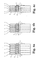
- a predetermined number (five in Fig. 4(a)) of the abrasive brushes 1 are arranged so that the projecting part 7 (in the cross-section A-A) of the hub 5 of one abrasive brush 1 is brought into contact with a flat part (in the cross-section A-A) which is neither the recessed part 9 nor the through-hole part 11 of the hub 5 of the adjacent abrasive brush 1, whereby the abrasive brushes are coupled together at a pitch (equal pitch) defined by the engagement relationship between the hubs to form an abrasive brush assembly.
- the brush sections 3 are minimally compressed to result in the abrasive brush assembly having the widest width.
- a predetermined number of the abrasive brushes 1 are arranged so that the projecting part 7 (in the cross-section A-A) of the hub 5 of one abrasive brush 1 is inserted into the recessed part 9 (in the cross-section B-B) which is neither the through-hole part 11 nor the flat part of the hub 5 of the adjacent abrasive brush 1, whereby the abrasive brushes are coupled together at a pitch (equal pitch) defined by the engagement relationship between the hubs to form an abrasive brush assembly.
- the brush sections 3 are more compressed compared to Fig. 4(a) to result in the abrasive brush assembly with a width narrower by a predetermined amount than in the embodiment of Fig. 4(a).
- a predetermined number of the abrasive brushes 1 are arranged so that the projecting part 7 (in the cross-section A-A) of the hub 5 of one abrasive brush 1 is inserted into the through-hole part 11 (in the cross-section C-C) which is neither the recessed part 9 nor the flat part of the hub 5 of the adjacent abrasive brush 1 (so that the flat portions of the adjacent hubs are brought in contact with each other), whereby the abrasive brushes are coupled together at a pitch (equal pitch) defined by the engagement relationship between the hubs to form an abrasive brush assembly with a width narrower than the brush assembly illustrated in Fig. 4(b).
- the present invention should not be limited to the above three embodiments, but includes various abrasive brush assemblies with different widths, and also having different brush surface hardness, by variously combining the projecting, recessed and through-hole parts of the assembly hubs.
- abrasive brush assemblies with different overall width dimensions by providing in the hub 5 of the abrasive brush 1 a so-called concave (the recessed part 9 and the through-hole 11) and a so-called convex (the projecting part 7) and differentiating the engagement relationship between the concave and the convex when the abrasive brushes are adjacent to each other to form the brush assembly.
- the compressive degree of the abrasive material i.e., the brush surface hardness is also variable.
- the hub provided in a central region (radial inner region) which ought to be required for a high compressive force in the prior art is formed of a solid member (which is not required to be compressed, in other words, which could be considered to have been compressed in advance to a predetermined dimension) and a portion necessary for being compressed during the process for superposing the abrasive brushes with each other is limited to the abrasive material section (radial outer region), a high compressive force (or installation) becomes unnecessary unlike the prior art.
- the customer at a job site can readily and quickly assemble a desired abrasive brush assembly.
- An abrasive brush 21 includes a brush section 3 and a hub 25.
- the hub 25 has a basic thickness, for example, approximately equal to half a thickness of the brush section 3 (radial outer abrasive material section) and is provided with a projecting part, recessed part and through-hole part. That is, in two cross-sections A-A' of the hub 25, a projecting part 27a extending parallel to the axial direction is provided on one side of the hub. On the other side of the radial inner section relative to the projecting part 27a, a recessed part 29a is provided, and a through-hole part 31 a is provided in a further radial inner section, wherein the recessed part 29a is continuous to the through-hole part 31 a.
- the projecting part 27a, the recessed part 29a and the through-hole part 31a are equi-distantly arranged at four positions on a predetermined diametrical circle on the one or other sides of the hub.
- a recessed part 29b is provided on one side, and a through-hole part 31b is provided in a further radial inner section, wherein the recessed part 29b is continuous to the through-hole part 31b.
- a projecting part 27b extending parallel to the axial direction is provided in another radial inner section.
- the recessed part 29b, the through-hole 31b and the projecting part 27b are equi-distantly arranged at four positions on a predetermined diametrical circle.
- a through-hole part 31c is provided and a projecting part 27c is provided on one side of a further inner section, while a recessed part 29c is provided on the other side of a the inner section.
- the recessed part 29c, the through-hole part 31c and the projecting part 27c are equi-distantly ranged at four positions on a predetermined diametrical circle.
- Each of the projecting parts 27a to 27c of the hub 25 have an approximately equal projected height and each of the recessed parts 29a to 29c has a depth approximately equal to half a projected height.
- abrasive brushes of the embodiment of Figs. 5-7 are arranged adjacent to each other, it is possible to obtain various abrasive brush assemblies having different width dimensions as well as brush surface hardness in accordance with manner of assembly similar to those already described with reference to the embodiment of Figs. 1-4.
- the concave and the through-hole and the convex features may be individually determined in consideration of the strength of material constituting the hub or the magnitude of torque applied on the brush when used. Since the structure is such that the brush pitch is defined when the projecting part is in contact with the bottom of the recessed part, it is favorable that the concave/convex engagement is made with sufficient mutual clearance; particularly, the projecting part is preferably, for example, of a trapezoidal cross-sectional shape so that it is easily engageable with and/or guided into the mating recess part.
- concave or the convex features are equi-distantly arranged at four positions on a predetermined diametrical circle in either of both the above-mentioned embodiments, the present invention should not be limited to only those embodiments. Unless a rotational balance becomes unstable, these features may be equi-distantly arranged optionally at N positions (N ⁇ 3).
- the through-hole provided at a center of the hub mainly serves for mounting the abrasive brush assembly on a rotary shaft, but may be used for the relative positioning and alignment of the brushes when they are superposed (assembled) with each other, or if necessary, another through-hole may be separately provided for this purpose.
- Any material may be used for forming the hub provided it has suitable processability, including materials such as plastics or resins, metal and wood. Plastics or resins are preferred because they are processable using molding methods, dimensional, stable, and lightweight.
- a flange may be attached to each of opposite sides of the brush to reduce a (so-called) blooming phenomenon of an outer peripheral edge of the brush.
- the above-mentioned two embodiments are those typically applied to an abrasive brush assembly used for a large-sized grinder.
- the present invention should not be limited to the application to such a large-sized device, but may be applied, for example, to a hand-held type grinder (a so-called straight grinder) not shown. That is, if the abrasive brush of the hand-held tool has the structure disclosed in the above-mentioned embodiments, it is possible to readily and quickly construct the abrasive brush assembly on site. Also, it is possible to obtain various brushes having different width dimensions by the simple angular positioning of adjacent hubs.
- a brush assembly having a desired width dimension and therefore a desired brush surface hardness can be extremely quickly, readily and simply constructed to provide a reasonable and economical abrasive brush.
Landscapes
- Engineering & Computer Science (AREA)
- Mechanical Engineering (AREA)
- Polishing Bodies And Polishing Tools (AREA)
- Brushes (AREA)
Applications Claiming Priority (3)
| Application Number | Priority Date | Filing Date | Title |
|---|---|---|---|
| JP255199 | 1999-01-08 | ||
| JP00255199A JP4493112B2 (ja) | 1999-01-08 | 1999-01-08 | 研磨ブラシ |
| US09/478,044 US6431971B2 (en) | 1999-01-08 | 2000-01-05 | Abrasive brush |
Publications (3)
| Publication Number | Publication Date |
|---|---|
| EP1018404A2 true EP1018404A2 (de) | 2000-07-12 |
| EP1018404A3 EP1018404A3 (de) | 2003-02-05 |
| EP1018404B1 EP1018404B1 (de) | 2004-12-08 |
Family
ID=26335952
Family Applications (1)
| Application Number | Title | Priority Date | Filing Date |
|---|---|---|---|
| EP00100110A Expired - Lifetime EP1018404B1 (de) | 1999-01-08 | 2000-01-05 | Schleifbürste |
Country Status (3)
| Country | Link |
|---|---|
| US (1) | US6431971B2 (de) |
| EP (1) | EP1018404B1 (de) |
| JP (1) | JP4493112B2 (de) |
Cited By (6)
| Publication number | Priority date | Publication date | Assignee | Title |
|---|---|---|---|---|
| EP1666230A1 (de) * | 2004-12-01 | 2006-06-07 | Gerd Elfgen | Vlieskörper und Verfahren zu dessen Herstellung |
| WO2007098045A1 (en) | 2006-02-17 | 2007-08-30 | 3M Innovative Properties Company | Sleeve for use in making abrasive articles |
| EP1986818A4 (de) * | 2006-02-17 | 2010-12-22 | 3M Innovative Properties Co | Schleifartikel mit einzelnen schleifelementen, wie z. b. klappen, und dessen herstellung |
| US8137423B2 (en) | 2004-08-20 | 2012-03-20 | 3M Innovative Properties Company | Method of making abrasive article |
| US8740675B2 (en) | 2009-12-25 | 2014-06-03 | 3M Innovative Properties Company | Method of making a grinding disk and a grinding disk |
| US9764449B2 (en) | 2014-05-29 | 2017-09-19 | Saint-Gobain Abrasives, Inc. | Abrasive article having a core including a polymer material |
Families Citing this family (11)
| Publication number | Priority date | Publication date | Assignee | Title |
|---|---|---|---|---|
| USD472565S1 (en) | 2002-05-30 | 2003-04-01 | Sanwa Kenma, Ltd. | Grindstone |
| US7121937B2 (en) * | 2003-03-17 | 2006-10-17 | 3M Innovative Properties Company | Abrasive brush elements and segments |
| JP2007030153A (ja) * | 2005-07-27 | 2007-02-08 | Kowa Co Ltd | ロール |
| US20080052857A1 (en) * | 2006-08-31 | 2008-03-06 | Mcconnell Richard George | Rotary scrub brush |
| JP5130430B2 (ja) * | 2007-02-02 | 2013-01-30 | 三光産業株式会社 | 表面処理用ブラシ |
| CN101332013B (zh) * | 2007-06-25 | 2011-10-05 | 3M创新有限公司 | 清洁刷 |
| US8579677B2 (en) | 2010-09-15 | 2013-11-12 | Saint-Gobain Abrasives, Inc. | Abrasive impregnated brush |
| US20130252521A1 (en) * | 2010-11-29 | 2013-09-26 | Shin-Etsu Chemical Co., Ltd. | Super hard alloy baseplate outer circumference cutting blade and manufacturing method thereof |
| JP5945679B2 (ja) * | 2012-07-17 | 2016-07-05 | 株式会社光陽社 | バリ取りブラシ用の研磨布紙保持具、及びこれを用いたバリ取りブラシ用のブラシ構成盤、並びにこれを積層して成るバリ取り用ブラシ |
| CN107378806A (zh) * | 2017-07-20 | 2017-11-24 | 江苏苏北砂轮厂有限公司 | 高厚度砂轮 |
| DE102022117629A1 (de) * | 2022-07-14 | 2024-01-25 | Eve Ernst Vetter Gmbh | Radialbürste für Schleif- oder Polierzwecke |
Family Cites Families (16)
| Publication number | Priority date | Publication date | Assignee | Title |
|---|---|---|---|---|
| US2720064A (en) * | 1954-04-07 | 1955-10-11 | Michael C Klug | Abrasive wheels |
| US2811816A (en) * | 1955-10-04 | 1957-11-05 | Back James | Tire and metal buffing tool |
| US3080637A (en) * | 1960-03-17 | 1963-03-12 | Albany Felt Co | Napping device for modifying the surface characteristic of a fibrous material |
| US5016311A (en) * | 1988-04-27 | 1991-05-21 | Minnesota Mining And Manufacturing Company | Apparatus and brush segment arrangement for finishing wheel brushes; and method |
| US4872292A (en) * | 1988-06-22 | 1989-10-10 | Aleck Block | Flap wheel |
| TW307801B (de) | 1992-03-19 | 1997-06-11 | Minnesota Mining & Mfg | |
| TW222668B (de) | 1992-03-19 | 1994-04-21 | Minnesota Mining & Mfg | |
| US5588172A (en) * | 1994-07-11 | 1996-12-31 | Abtex Corporation | Radial brush |
| JP3549923B2 (ja) | 1994-07-13 | 2004-08-04 | ミネソタ マイニング アンド マニュファクチャリング カンパニー | 研磨ディスク工具用保持具 |
| US5554068A (en) * | 1994-12-13 | 1996-09-10 | Minnesota Mining And Manufacturing Company | Abrasive flap brush and method and apparatus for making same |
| US5679067A (en) * | 1995-04-28 | 1997-10-21 | Minnesota Mining And Manufacturing Company | Molded abrasive brush |
| MX9708204A (es) | 1995-04-28 | 1997-12-31 | Minnesota Mining & Mfg | Articulo abrasivo que tiene un sistema de adhesion que comprende un polisiloxano. |
| US5903951A (en) | 1995-11-16 | 1999-05-18 | Minnesota Mining And Manufacturing Company | Molded brush segment |
| JP3708610B2 (ja) | 1996-01-26 | 2005-10-19 | ミネソタ マイニング アンド マニュファクチャリング カンパニー | 研磨ブラシとその製造方法 |
| US5964006A (en) | 1997-01-13 | 1999-10-12 | 3M Innovative Properties Company | Rotary surface treatment tool |
| US5983434A (en) | 1997-07-15 | 1999-11-16 | Minnesota Mining And Manufacturing Company | Rotary bristle tool with preferentially oriented bristles |
-
1999
- 1999-01-08 JP JP00255199A patent/JP4493112B2/ja not_active Expired - Lifetime
-
2000
- 2000-01-05 EP EP00100110A patent/EP1018404B1/de not_active Expired - Lifetime
- 2000-01-05 US US09/478,044 patent/US6431971B2/en not_active Expired - Lifetime
Cited By (8)
| Publication number | Priority date | Publication date | Assignee | Title |
|---|---|---|---|---|
| US8137423B2 (en) | 2004-08-20 | 2012-03-20 | 3M Innovative Properties Company | Method of making abrasive article |
| EP1666230A1 (de) * | 2004-12-01 | 2006-06-07 | Gerd Elfgen | Vlieskörper und Verfahren zu dessen Herstellung |
| WO2007098045A1 (en) | 2006-02-17 | 2007-08-30 | 3M Innovative Properties Company | Sleeve for use in making abrasive articles |
| EP1986821A4 (de) * | 2006-02-17 | 2009-08-19 | 3M Innovative Properties Co | Hülse zur verwendung bei der herstellung von schleifartikeln |
| EP1986818A4 (de) * | 2006-02-17 | 2010-12-22 | 3M Innovative Properties Co | Schleifartikel mit einzelnen schleifelementen, wie z. b. klappen, und dessen herstellung |
| US8740675B2 (en) | 2009-12-25 | 2014-06-03 | 3M Innovative Properties Company | Method of making a grinding disk and a grinding disk |
| US9764449B2 (en) | 2014-05-29 | 2017-09-19 | Saint-Gobain Abrasives, Inc. | Abrasive article having a core including a polymer material |
| US10213903B2 (en) | 2014-05-29 | 2019-02-26 | Saint-Gobain Abrasives, Inc. | Abrasive article having a core including a polymer material |
Also Published As
| Publication number | Publication date |
|---|---|
| EP1018404B1 (de) | 2004-12-08 |
| EP1018404A3 (de) | 2003-02-05 |
| US6431971B2 (en) | 2002-08-13 |
| JP4493112B2 (ja) | 2010-06-30 |
| JP2000198078A (ja) | 2000-07-18 |
| US20010041528A1 (en) | 2001-11-15 |
Similar Documents
| Publication | Publication Date | Title |
|---|---|---|
| US6431971B2 (en) | Abrasive brush | |
| US10414012B2 (en) | Grinding pad apparatus | |
| AU2020202149B2 (en) | Polishing or grinding pad assembly | |
| EP3348352B1 (de) | Schleifkissenvorrichtung | |
| US5281244A (en) | Flexible abrasive pad with ramp edge surface | |
| EP3737530B1 (de) | Polier- oder schleifkissen mit mehrschichtverstärkung | |
| DE69905135T2 (de) | Poliermaschine mit einem Drehkopf, der eine Vielzahl von Poliersektoren mit segmentierten und elastischen Strukturen trägt | |
| CN102026777B (zh) | 粗磨磨削盘 | |
| US5628679A (en) | Holder for an abrading disk tool | |
| JPH01103268A (ja) | ブラシロール | |
| JPS6254632B2 (de) | ||
| CN117769479A (zh) | 抛光刷系统 | |
| KR102779210B1 (ko) | 연삭용 컵 휠 | |
| EP1657462A1 (de) | Kupplungsreibbelag | |
| JPH0637669Y2 (ja) | 製麺用切刃ロール | |
| KR101321154B1 (ko) | 연마휠 | |
| JPS60109764U (ja) | せんい強化プラスチツク材料切断用カツタ− | |
| AU2001239025A1 (en) | Surface finishing pad |
Legal Events
| Date | Code | Title | Description |
|---|---|---|---|
| PUAI | Public reference made under article 153(3) epc to a published international application that has entered the european phase |
Free format text: ORIGINAL CODE: 0009012 |
|
| AK | Designated contracting states |
Kind code of ref document: A2 Designated state(s): DE FR GB |
|
| AX | Request for extension of the european patent |
Free format text: AL;LT;LV;MK;RO;SI |
|
| PUAL | Search report despatched |
Free format text: ORIGINAL CODE: 0009013 |
|
| AK | Designated contracting states |
Designated state(s): DE FR GB |
|
| AX | Request for extension of the european patent |
Extension state: AL LT LV MK RO SI |
|
| 17P | Request for examination filed |
Effective date: 20030805 |
|
| AKX | Designation fees paid |
Designated state(s): DE FR GB |
|
| 17Q | First examination report despatched |
Effective date: 20031107 |
|
| GRAP | Despatch of communication of intention to grant a patent |
Free format text: ORIGINAL CODE: EPIDOSNIGR1 |
|
| RIN1 | Information on inventor provided before grant (corrected) |
Inventor name: NAGAFUCHI, NAOHIRO |
|
| GRAA | (expected) grant |
Free format text: ORIGINAL CODE: 0009210 |
|
| GRAS | Grant fee paid |
Free format text: ORIGINAL CODE: EPIDOSNIGR3 |
|
| AK | Designated contracting states |
Kind code of ref document: B1 Designated state(s): DE FR GB |
|
| REG | Reference to a national code |
Ref country code: GB Ref legal event code: FG4D |
|
| REF | Corresponds to: |
Ref document number: 60016472 Country of ref document: DE Date of ref document: 20050113 Kind code of ref document: P |
|
| PLBE | No opposition filed within time limit |
Free format text: ORIGINAL CODE: 0009261 |
|
| STAA | Information on the status of an ep patent application or granted ep patent |
Free format text: STATUS: NO OPPOSITION FILED WITHIN TIME LIMIT |
|
| 26N | No opposition filed |
Effective date: 20050909 |
|
| ET | Fr: translation filed | ||
| PGFP | Annual fee paid to national office [announced via postgrant information from national office to epo] |
Ref country code: GB Payment date: 20051229 Year of fee payment: 7 |
|
| PGFP | Annual fee paid to national office [announced via postgrant information from national office to epo] |
Ref country code: FR Payment date: 20060117 Year of fee payment: 7 |
|
| PGFP | Annual fee paid to national office [announced via postgrant information from national office to epo] |
Ref country code: DE Payment date: 20060228 Year of fee payment: 7 |
|
| PG25 | Lapsed in a contracting state [announced via postgrant information from national office to epo] |
Ref country code: DE Free format text: LAPSE BECAUSE OF NON-PAYMENT OF DUE FEES Effective date: 20070801 |
|
| GBPC | Gb: european patent ceased through non-payment of renewal fee |
Effective date: 20070105 |
|
| REG | Reference to a national code |
Ref country code: FR Ref legal event code: ST Effective date: 20070930 |
|
| PG25 | Lapsed in a contracting state [announced via postgrant information from national office to epo] |
Ref country code: GB Free format text: LAPSE BECAUSE OF NON-PAYMENT OF DUE FEES Effective date: 20070105 |
|
| PG25 | Lapsed in a contracting state [announced via postgrant information from national office to epo] |
Ref country code: FR Free format text: LAPSE BECAUSE OF NON-PAYMENT OF DUE FEES Effective date: 20070131 |