EP1018828A2 - Corrélateur et procédé de corrélation d'interval de garde pour signaux OFDM - Google Patents
Corrélateur et procédé de corrélation d'interval de garde pour signaux OFDM Download PDFInfo
- Publication number
- EP1018828A2 EP1018828A2 EP99125963A EP99125963A EP1018828A2 EP 1018828 A2 EP1018828 A2 EP 1018828A2 EP 99125963 A EP99125963 A EP 99125963A EP 99125963 A EP99125963 A EP 99125963A EP 1018828 A2 EP1018828 A2 EP 1018828A2
- Authority
- EP
- European Patent Office
- Prior art keywords
- output
- guard interval
- correlation
- correlator
- reset pulse
- Prior art date
- Legal status (The legal status is an assumption and is not a legal conclusion. Google has not performed a legal analysis and makes no representation as to the accuracy of the status listed.)
- Withdrawn
Links
Images



Classifications
-
- H—ELECTRICITY
- H04—ELECTRIC COMMUNICATION TECHNIQUE
- H04L—TRANSMISSION OF DIGITAL INFORMATION, e.g. TELEGRAPHIC COMMUNICATION
- H04L27/00—Modulated-carrier systems
- H04L27/26—Systems using multi-frequency codes
- H04L27/2601—Multicarrier modulation systems
- H04L27/2647—Arrangements specific to the receiver only
- H04L27/2655—Synchronisation arrangements
- H04L27/2662—Symbol synchronisation
-
- H—ELECTRICITY
- H04—ELECTRIC COMMUNICATION TECHNIQUE
- H04L—TRANSMISSION OF DIGITAL INFORMATION, e.g. TELEGRAPHIC COMMUNICATION
- H04L27/00—Modulated-carrier systems
- H04L27/26—Systems using multi-frequency codes
- H04L27/2601—Multicarrier modulation systems
- H04L27/2647—Arrangements specific to the receiver only
- H04L27/2655—Synchronisation arrangements
- H04L27/2668—Details of algorithms
- H04L27/2673—Details of algorithms characterised by synchronisation parameters
- H04L27/2676—Blind, i.e. without using known symbols
- H04L27/2678—Blind, i.e. without using known symbols using cyclostationarities, e.g. cyclic prefix or postfix
-
- H—ELECTRICITY
- H04—ELECTRIC COMMUNICATION TECHNIQUE
- H04L—TRANSMISSION OF DIGITAL INFORMATION, e.g. TELEGRAPHIC COMMUNICATION
- H04L7/00—Arrangements for synchronising receiver with transmitter
- H04L7/04—Speed or phase control by synchronisation signals
- H04L7/041—Speed or phase control by synchronisation signals using special codes as synchronising signal
- H04L2007/045—Fill bit or bits, idle words
Definitions
- the present invention relates to a guard interval correlator suitable for the calculation of a guard interval correlation, and a correlation producing method therefore.
- An OFDM (Orthogonal Frequency Division Multiplexing) system belongs to a family of systems available for transmitting, e.g., coded digital video signals by use of a limited frequency band.
- the OFDM system sends digital information subjected to QAM (256 Quadrature Amplitude Modulation) or similar multilevel modulation by using a number of carrier waves.
- QAM 256 Quadrature Amplitude Modulation
- the OFDM system includes a guard interval correlator or synchronizing circuit for calculating a guard interval correlation.
- a conventional guard interval correlator has the following problems left unsolved. Assume that a guard interval has a length N. Then, to calculate n newest cumulative values (correlation values) by real-time operation, N accumulators are necessary. The number of required accumulators increases with an increase in the guard interval length N, scaling up the circuitry. Should the frequency of accumulation be reduced in order to scale down the circuitry, the calculation or correlation would lack in accuracy.
- a guard interval correlator includes a first delay for delaying an input value by the length of a guard interval.
- a subtractor performs subtraction with the output of the first delay and a correlation output delayed by one clock.
- An adder adds the input value and the output of the subtractor.
- a second delays the output of the adder by one clock to thereby output the correlation output, and feeds the correlation output to the subtractor.
- a method of producing a guard interval correlation includes the steps of delaying an input value by the length of a guard interval to thereby produce a delayed output, executing subtraction with the delayed output and a correlation output delayed by one clock to thereby produce a difference, adding the input value and the difference to thereby produce a sum, and delaying the sum by one clock to thereby produce the correlation output and feeding the correlation output to the subtraction step.
- the guard interval correlator includes accumulators 6 through 9, a selector 10, and a timing adjuster 11.
- the accumulators 6 through 9 each accumulate one to N data (products).
- the selector 10 selects one of the outputs of the accumulators 6 through 9 at a time and outputs it.
- the timing adjuster 11 generates timing signals for resetting the accumulators 6 through 9 and a timing signal for switching the selector 10. Specifically, the timing adjuster 11 sequentially shifts the accumulating operations of the accumulators 6 through 9 by one clock and shifts the selecting operation of the selector 10 by one clock.
- the accumulators 6 through 9 each repeatedly perform calculation during intervals indicated by arrows in FIG. 2 under the control of the timing adjuster 11. At the end of calculation, the selector 10 outputs the result of calculation (correlation value) under the control of the timing adjuster 11.
- a guard interval correlator of the present invention delays an input value by the length of a guard interval, performs subtraction with the delayed input value and a correlation output delayed by one clock, adds the input value and the result of subtraction, and delays the resulting sum by one clock to thereby produce a correlation output.
- the correlator includes a delay or first delay means 1, a subtraction 2, an addition 3, a resetting 4, and a delay or second delay means 5.
- the delay 1 delays an input value (product) by the length of a guard interval.
- the subtraction 2 subtracts the output of the delay 1 from a correlation value output from the delay 5.
- the addition 3 adds the product input thereto and the output of the subtraction 2.
- the resetting 4 resets the delay 1, subtraction 2, and addition 3.
- the delay 5 delays the output of the addition 3 by one clock.
- the resetting 4 monitors the statuses of the resetting 4, delay 1, subtraction 2 and addition 3 and generates a reset pulse when any one of them varies.
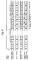
- the delay 1, subtraction 2 and addition 3 are reset to "0" by the reset pulse output form the resetting 4 (RESETTING OPERATION, FIG. 4).
- data (product) A1 is input just after the resetting, that data A2, A3 and so forth follow the data A1, and that a guard interval has a length n .
- the delay 1 delays the data by n clocks, i.e., outputs "0” over the duration of n clocks and outputs the data A1 after the "n+1" clock.
- the output of the delay 1 to the subtraction 2 and the output of the delay 5 both are "0", so that the output of the subtraction 2 is also "0".
- the input data A1 appears on the output terminal of the addition 3.
- the delay 5 delays this data A1 by one clock to thereby output a correlation.
- One clock later than the reset pulse the data A1 and "0" are input to the subtraction 2.
- the subtraction 2 subtracts "0" from the data A1 and therefore outputs the data A1.
- the data A1 output form the subtraction 2 and the data A2 input one clock later than the data A1 are input to the addition 3.
- the addition 3 produces (A1 + A2) and feeds it to the delay 5.
- the delay 5 delays the sum output from the addition 3 by one clock to thereby produce a correlation. Assume that the correlation output form the delay 5 is S(1,2).
- the above procedure is repeated n consecutive times to produce S(1,n).
- the correlator After the resetting operation, the correlator operates in a usual mode (USUAL OPERATION, FIG. 4). During usual operation, n (guard interval length) newest cumulative values are needed. At the time when the above resetting operation ends, n newest cumulative values (correlation values) have been obtained.
- the delay 1 After the input of the "n+1" clock, the delay 1 outputs A1 with the result that the subtraction 2 calculates S(1,n) - A1.
- the addition 3 adds An + 1 to the resulting output of the subtraction 2 and thereby produces S(1,n) - A1 + (An + 1) which is equal to S(2, n+1). This procedure is repeated to produce n newest cumulative values at all times.
- the delay 1 delays an input value by the length of a guard interval while the subtraction 2 subtracts a correlation delayed by one clock from a delayed output.
- the addition 3 adds the input value and the delayed output.
- the delay 5 delays the resulting sum by one clock to thereby output a correlation. This is successful to prevent the circuitry from being scaled up without degrading the accuracy of the correlation.
- FIG. 5 shows an alternative embodiment of the present invention.
- the subtraction 2 is connected to the outside side of the addition 3 in order to perform subtraction with the output of the addition 3 and that of the delay 1.
- the alternative embodiment achieves the same advantage as the previous embodiment.
- the present invention provides a guard interval correlator capable of insuring accurate correlations with a minimum of circuit scale, and a correlation producing method therefore.
Landscapes
- Engineering & Computer Science (AREA)
- Computer Networks & Wireless Communication (AREA)
- Signal Processing (AREA)
- Synchronisation In Digital Transmission Systems (AREA)
Applications Claiming Priority (2)
| Application Number | Priority Date | Filing Date | Title |
|---|---|---|---|
| JP11000115A JP3082757B2 (ja) | 1999-01-04 | 1999-01-04 | ガードインターバル相関器及びその相関取得方法 |
| JP11599 | 1999-01-04 |
Publications (2)
| Publication Number | Publication Date |
|---|---|
| EP1018828A2 true EP1018828A2 (fr) | 2000-07-12 |
| EP1018828A3 EP1018828A3 (fr) | 2003-02-05 |
Family
ID=11465066
Family Applications (1)
| Application Number | Title | Priority Date | Filing Date |
|---|---|---|---|
| EP99125963A Withdrawn EP1018828A3 (fr) | 1999-01-04 | 1999-12-27 | Corrélateur et procédé de corrélation d'interval de garde pour signaux OFDM |
Country Status (2)
| Country | Link |
|---|---|
| EP (1) | EP1018828A3 (fr) |
| JP (1) | JP3082757B2 (fr) |
Cited By (3)
| Publication number | Priority date | Publication date | Assignee | Title |
|---|---|---|---|---|
| GB2382963A (en) * | 2001-11-13 | 2003-06-11 | Nec Corp | Adaptive optimal guard interval length determination in an OFDM receiver |
| US20100183099A1 (en) * | 2007-04-24 | 2010-07-22 | Kyocera Corporation | Reception Control Method and Wireless Communication Apparatus |
| US8005157B2 (en) * | 2007-08-24 | 2011-08-23 | Oki Semiconductor Co., Ltd. | Correlation calculation unit and correlation calculation apparatus |
Family Cites Families (4)
| Publication number | Priority date | Publication date | Assignee | Title |
|---|---|---|---|---|
| JP2603134B2 (ja) * | 1989-06-06 | 1997-04-23 | 三菱電機株式会社 | 移動平均処理装置 |
| SE514986C2 (sv) * | 1995-03-01 | 2001-05-28 | Telia Ab | Metod och anordning för synkronisering vid OFDM-system |
| GB2307155B (en) * | 1995-11-02 | 1999-09-15 | British Broadcasting Corp | Synchronisation of OFDM signals |
| DE69739012D1 (de) * | 1997-09-04 | 2008-11-06 | Sony Deutschland Gmbh | Übertragungssystem für OFDM-Signale mit optimierter Synchronisation |
-
1999
- 1999-01-04 JP JP11000115A patent/JP3082757B2/ja not_active Expired - Lifetime
- 1999-12-27 EP EP99125963A patent/EP1018828A3/fr not_active Withdrawn
Cited By (6)
| Publication number | Priority date | Publication date | Assignee | Title |
|---|---|---|---|---|
| GB2382963A (en) * | 2001-11-13 | 2003-06-11 | Nec Corp | Adaptive optimal guard interval length determination in an OFDM receiver |
| GB2382963B (en) * | 2001-11-13 | 2004-03-10 | Nec Corp | Guard interval length control method in OFDM, and related OFDM system, transmitting and receiving apparatuses |
| US7336598B2 (en) | 2001-11-13 | 2008-02-26 | Nec Corporation | Guard interval length control method in OFDM system and OFDM transmitting and receiving apparatuses |
| US20100183099A1 (en) * | 2007-04-24 | 2010-07-22 | Kyocera Corporation | Reception Control Method and Wireless Communication Apparatus |
| US8467484B2 (en) * | 2007-04-24 | 2013-06-18 | Kyocera Corporation | Reception control method and wireless communication apparatus |
| US8005157B2 (en) * | 2007-08-24 | 2011-08-23 | Oki Semiconductor Co., Ltd. | Correlation calculation unit and correlation calculation apparatus |
Also Published As
| Publication number | Publication date |
|---|---|
| EP1018828A3 (fr) | 2003-02-05 |
| JP2000201129A (ja) | 2000-07-18 |
| JP3082757B2 (ja) | 2000-08-28 |
Similar Documents
| Publication | Publication Date | Title |
|---|---|---|
| EP0829988B1 (fr) | Synchronisation par symbole et réglage de la fréquence d'échantillonnage dans un récepteur pour MDFO | |
| US5940458A (en) | Method and compensating for time error of time/frequency generator using global positioning system | |
| JP2006502665A (ja) | 受信信号の直接取得のためのシステム | |
| EP0802644A3 (fr) | Système de communication à multiplexage fréquentiel à largeur de bande variable | |
| CN112953593B (zh) | LoRa高级接收器 | |
| EP0729679B1 (fr) | Dispositif et procede d'estimation efficacement de la synchronisation dans un recepteur numerique | |
| EP1018828A2 (fr) | Corrélateur et procédé de corrélation d'interval de garde pour signaux OFDM | |
| JP2005527154A (ja) | 信号およびエコーの受信時の同期のための方法および装置 | |
| KR101278031B1 (ko) | 병렬 자동 주파수 오프셋 추정장치 및 방법 | |
| JP4644713B2 (ja) | 相関値を決定するための装置および方法 | |
| JP2003338775A (ja) | 符号分割多重伝送システム、送信装置、受信装置、送信方法、受信方法、符号生成装置、符号生成方法、ならびに、プログラム | |
| JP3406167B2 (ja) | 同期装置 | |
| JP7027216B2 (ja) | 放送波中継システム及び放送波中継方法 | |
| JP3686547B2 (ja) | 受信装置 | |
| JP4791307B2 (ja) | 受信装置、中継装置のサンプリングクロック制御方法 | |
| KR20060015306A (ko) | 수신된 데이터의 위상을 추적하는 위상 추적기, 이러한위상 추적기를 포함하는 시스템, 디바이스, 프로세서, 위상추적 방법 및 프로세서 프로그램 제품 | |
| JP3639120B2 (ja) | 拡散変調信号受信装置 | |
| US20250184202A1 (en) | Device for synchronizing a symbol clock during data transmission and transmission system | |
| JP2005064983A (ja) | スペクトラム拡散信号受信装置 | |
| JP3584393B2 (ja) | ガード相関器 | |
| KR20000048164A (ko) | 기지국 장치 및 송신 브랜치 선택 방법 | |
| JP3688147B2 (ja) | サンプリングシステム | |
| JPH0354981A (ja) | 振幅評価装置 | |
| US5995535A (en) | Rapid time and frequency acquistion of spread spectrum waveforms via ambiguity transform | |
| JP2963431B1 (ja) | Ofdm信号同期装置 |
Legal Events
| Date | Code | Title | Description |
|---|---|---|---|
| PUAI | Public reference made under article 153(3) epc to a published international application that has entered the european phase |
Free format text: ORIGINAL CODE: 0009012 |
|
| AK | Designated contracting states |
Kind code of ref document: A2 Designated state(s): AT BE CH CY DE DK ES FI FR GB GR IE IT LI LU MC NL PT SE |
|
| AX | Request for extension of the european patent |
Free format text: AL;LT;LV;MK;RO;SI |
|
| PUAL | Search report despatched |
Free format text: ORIGINAL CODE: 0009013 |
|
| AK | Designated contracting states |
Designated state(s): AT BE CH CY DE DK ES FI FR GB GR IE IT LI LU MC NL PT SE |
|
| AX | Request for extension of the european patent |
Extension state: AL LT LV MK RO SI |
|
| 17P | Request for examination filed |
Effective date: 20030110 |
|
| 17Q | First examination report despatched |
Effective date: 20030417 |
|
| STAA | Information on the status of an ep patent application or granted ep patent |
Free format text: STATUS: THE APPLICATION HAS BEEN WITHDRAWN |
|
| 18W | Application withdrawn |
Effective date: 20030711 |