EP1022811B1 - Interconnecteur électrique du type à contact par pression et méthode de sa fabrication - Google Patents
Interconnecteur électrique du type à contact par pression et méthode de sa fabrication Download PDFInfo
- Publication number
- EP1022811B1 EP1022811B1 EP00100607A EP00100607A EP1022811B1 EP 1022811 B1 EP1022811 B1 EP 1022811B1 EP 00100607 A EP00100607 A EP 00100607A EP 00100607 A EP00100607 A EP 00100607A EP 1022811 B1 EP1022811 B1 EP 1022811B1
- Authority
- EP
- European Patent Office
- Prior art keywords
- insulative
- rubber sheet
- sheet
- conductive threads
- foam
- Prior art date
- Legal status (The legal status is an assumption and is not a legal conclusion. Google has not performed a legal analysis and makes no representation as to the accuracy of the status listed.)
- Expired - Lifetime
Links
- 238000004519 manufacturing process Methods 0.000 title claims description 18
- 229920001971 elastomer Polymers 0.000 claims abstract description 163
- 229920001821 foam rubber Polymers 0.000 claims abstract description 49
- 230000001681 protective effect Effects 0.000 claims abstract description 32
- 239000011295 pitch Substances 0.000 claims abstract description 14
- 239000000463 material Substances 0.000 claims description 69
- 238000000465 moulding Methods 0.000 claims description 35
- 239000006260 foam Substances 0.000 claims description 31
- 238000003825 pressing Methods 0.000 claims description 9
- 239000004020 conductor Substances 0.000 claims description 4
- 238000005452 bending Methods 0.000 claims description 3
- 238000005520 cutting process Methods 0.000 claims description 3
- 238000010438 heat treatment Methods 0.000 claims description 3
- 238000005187 foaming Methods 0.000 claims description 2
- 238000010030 laminating Methods 0.000 claims description 2
- 238000000034 method Methods 0.000 claims 7
- 229920002379 silicone rubber Polymers 0.000 description 50
- 239000004945 silicone rubber Substances 0.000 description 50
- 229910052751 metal Inorganic materials 0.000 description 16
- 239000002184 metal Substances 0.000 description 16
- 239000003795 chemical substances by application Substances 0.000 description 10
- 150000001875 compounds Chemical class 0.000 description 10
- 229920000139 polyethylene terephthalate Polymers 0.000 description 9
- 239000005020 polyethylene terephthalate Substances 0.000 description 9
- 238000004073 vulcanization Methods 0.000 description 9
- 230000000694 effects Effects 0.000 description 7
- 239000004973 liquid crystal related substance Substances 0.000 description 7
- 238000002156 mixing Methods 0.000 description 7
- 239000011888 foil Substances 0.000 description 6
- -1 polyethylene terephthalate Polymers 0.000 description 6
- 230000002950 deficient Effects 0.000 description 4
- 238000010348 incorporation Methods 0.000 description 4
- 238000011417 postcuring Methods 0.000 description 4
- 238000002360 preparation method Methods 0.000 description 4
- 229910001020 Au alloy Inorganic materials 0.000 description 3
- 229910001369 Brass Inorganic materials 0.000 description 3
- 230000032683 aging Effects 0.000 description 3
- 239000010951 brass Substances 0.000 description 3
- 239000000806 elastomer Substances 0.000 description 3
- 239000004088 foaming agent Substances 0.000 description 3
- PCHJSUWPFVWCPO-UHFFFAOYSA-N gold Chemical compound [Au] PCHJSUWPFVWCPO-UHFFFAOYSA-N 0.000 description 3
- 229910052737 gold Inorganic materials 0.000 description 3
- 239000010931 gold Substances 0.000 description 3
- 239000003353 gold alloy Substances 0.000 description 3
- 239000000126 substance Substances 0.000 description 3
- 229910000906 Bronze Inorganic materials 0.000 description 2
- KAKZBPTYRLMSJV-UHFFFAOYSA-N Butadiene Chemical compound C=CC=C KAKZBPTYRLMSJV-UHFFFAOYSA-N 0.000 description 2
- RYGMFSIKBFXOCR-UHFFFAOYSA-N Copper Chemical compound [Cu] RYGMFSIKBFXOCR-UHFFFAOYSA-N 0.000 description 2
- YCKRFDGAMUMZLT-UHFFFAOYSA-N Fluorine atom Chemical compound [F] YCKRFDGAMUMZLT-UHFFFAOYSA-N 0.000 description 2
- XEEYBQQBJWHFJM-UHFFFAOYSA-N Iron Chemical compound [Fe] XEEYBQQBJWHFJM-UHFFFAOYSA-N 0.000 description 2
- PXHVJJICTQNCMI-UHFFFAOYSA-N Nickel Chemical compound [Ni] PXHVJJICTQNCMI-UHFFFAOYSA-N 0.000 description 2
- 239000004698 Polyethylene Substances 0.000 description 2
- 239000006087 Silane Coupling Agent Substances 0.000 description 2
- 229920006311 Urethane elastomer Polymers 0.000 description 2
- 230000002411 adverse Effects 0.000 description 2
- 239000010974 bronze Substances 0.000 description 2
- 229920005549 butyl rubber Polymers 0.000 description 2
- 229910052802 copper Inorganic materials 0.000 description 2
- 239000010949 copper Substances 0.000 description 2
- KUNSUQLRTQLHQQ-UHFFFAOYSA-N copper tin Chemical compound [Cu].[Sn] KUNSUQLRTQLHQQ-UHFFFAOYSA-N 0.000 description 2
- 238000013461 design Methods 0.000 description 2
- 230000007613 environmental effect Effects 0.000 description 2
- 239000000945 filler Substances 0.000 description 2
- 239000011737 fluorine Substances 0.000 description 2
- 229910052731 fluorine Inorganic materials 0.000 description 2
- 238000007429 general method Methods 0.000 description 2
- 229920003049 isoprene rubber Polymers 0.000 description 2
- 150000002739 metals Chemical class 0.000 description 2
- 150000002825 nitriles Chemical class 0.000 description 2
- 230000036961 partial effect Effects 0.000 description 2
- 230000002093 peripheral effect Effects 0.000 description 2
- 238000007747 plating Methods 0.000 description 2
- BASFCYQUMIYNBI-UHFFFAOYSA-N platinum Chemical compound [Pt] BASFCYQUMIYNBI-UHFFFAOYSA-N 0.000 description 2
- 229920001084 poly(chloroprene) Polymers 0.000 description 2
- 229920001707 polybutylene terephthalate Polymers 0.000 description 2
- 229920006267 polyester film Polymers 0.000 description 2
- 229920000573 polyethylene Polymers 0.000 description 2
- 229920001721 polyimide Polymers 0.000 description 2
- 229920001296 polysiloxane Polymers 0.000 description 2
- 229910052703 rhodium Inorganic materials 0.000 description 2
- 239000010948 rhodium Substances 0.000 description 2
- MHOVAHRLVXNVSD-UHFFFAOYSA-N rhodium atom Chemical compound [Rh] MHOVAHRLVXNVSD-UHFFFAOYSA-N 0.000 description 2
- 229910001220 stainless steel Inorganic materials 0.000 description 2
- 239000010935 stainless steel Substances 0.000 description 2
- ZOKXTWBITQBERF-UHFFFAOYSA-N Molybdenum Chemical compound [Mo] ZOKXTWBITQBERF-UHFFFAOYSA-N 0.000 description 1
- 229920000459 Nitrile rubber Polymers 0.000 description 1
- OAICVXFJPJFONN-UHFFFAOYSA-N Phosphorus Chemical compound [P] OAICVXFJPJFONN-UHFFFAOYSA-N 0.000 description 1
- 229910000676 Si alloy Inorganic materials 0.000 description 1
- 229910001069 Ti alloy Inorganic materials 0.000 description 1
- 229920002433 Vinyl chloride-vinyl acetate copolymer Polymers 0.000 description 1
- CSDREXVUYHZDNP-UHFFFAOYSA-N alumanylidynesilicon Chemical compound [Al].[Si] CSDREXVUYHZDNP-UHFFFAOYSA-N 0.000 description 1
- 229910052782 aluminium Inorganic materials 0.000 description 1
- XAGFODPZIPBFFR-UHFFFAOYSA-N aluminium Chemical compound [Al] XAGFODPZIPBFFR-UHFFFAOYSA-N 0.000 description 1
- 229910052790 beryllium Inorganic materials 0.000 description 1
- ATBAMAFKBVZNFJ-UHFFFAOYSA-N beryllium atom Chemical compound [Be] ATBAMAFKBVZNFJ-UHFFFAOYSA-N 0.000 description 1
- 230000015572 biosynthetic process Effects 0.000 description 1
- NTXGQCSETZTARF-UHFFFAOYSA-N buta-1,3-diene;prop-2-enenitrile Chemical compound C=CC=C.C=CC#N NTXGQCSETZTARF-UHFFFAOYSA-N 0.000 description 1
- MTAZNLWOLGHBHU-UHFFFAOYSA-N butadiene-styrene rubber Chemical compound C=CC=C.C=CC1=CC=CC=C1 MTAZNLWOLGHBHU-UHFFFAOYSA-N 0.000 description 1
- YACLQRRMGMJLJV-UHFFFAOYSA-N chloroprene Chemical compound ClC(=C)C=C YACLQRRMGMJLJV-UHFFFAOYSA-N 0.000 description 1
- 230000000052 comparative effect Effects 0.000 description 1
- 230000006835 compression Effects 0.000 description 1
- 238000007906 compression Methods 0.000 description 1
- 238000010276 construction Methods 0.000 description 1
- 229920001577 copolymer Polymers 0.000 description 1
- IUYOGGFTLHZHEG-UHFFFAOYSA-N copper titanium Chemical compound [Ti].[Cu] IUYOGGFTLHZHEG-UHFFFAOYSA-N 0.000 description 1
- 230000003247 decreasing effect Effects 0.000 description 1
- 230000005489 elastic deformation Effects 0.000 description 1
- 229910052742 iron Inorganic materials 0.000 description 1
- 229910052750 molybdenum Inorganic materials 0.000 description 1
- 239000011733 molybdenum Substances 0.000 description 1
- 229910052759 nickel Inorganic materials 0.000 description 1
- 239000010956 nickel silver Substances 0.000 description 1
- 231100000252 nontoxic Toxicity 0.000 description 1
- 230000003000 nontoxic effect Effects 0.000 description 1
- 229910052697 platinum Inorganic materials 0.000 description 1
- 229920000642 polymer Polymers 0.000 description 1
- 239000004814 polyurethane Substances 0.000 description 1
- 229920003225 polyurethane elastomer Polymers 0.000 description 1
- 230000002829 reductive effect Effects 0.000 description 1
- 230000006641 stabilisation Effects 0.000 description 1
- 238000011105 stabilization Methods 0.000 description 1
- 230000001629 suppression Effects 0.000 description 1
- WFKWXMTUELFFGS-UHFFFAOYSA-N tungsten Chemical compound [W] WFKWXMTUELFFGS-UHFFFAOYSA-N 0.000 description 1
- 229910052721 tungsten Inorganic materials 0.000 description 1
- 239000010937 tungsten Substances 0.000 description 1
- 238000004804 winding Methods 0.000 description 1
Images


Classifications
-
- H—ELECTRICITY
- H01—ELECTRIC ELEMENTS
- H01R—ELECTRICALLY-CONDUCTIVE CONNECTIONS; STRUCTURAL ASSOCIATIONS OF A PLURALITY OF MUTUALLY-INSULATED ELECTRICAL CONNECTING ELEMENTS; COUPLING DEVICES; CURRENT COLLECTORS
- H01R13/00—Details of coupling devices of the kinds covered by groups H01R12/70 or H01R24/00 - H01R33/00
- H01R13/02—Contact members
- H01R13/22—Contacts for co-operating by abutting
- H01R13/24—Contacts for co-operating by abutting resilient; resiliently-mounted
- H01R13/2407—Contacts for co-operating by abutting resilient; resiliently-mounted characterized by the resilient means
- H01R13/2414—Contacts for co-operating by abutting resilient; resiliently-mounted characterized by the resilient means conductive elastomers
-
- H—ELECTRICITY
- H01—ELECTRIC ELEMENTS
- H01R—ELECTRICALLY-CONDUCTIVE CONNECTIONS; STRUCTURAL ASSOCIATIONS OF A PLURALITY OF MUTUALLY-INSULATED ELECTRICAL CONNECTING ELEMENTS; COUPLING DEVICES; CURRENT COLLECTORS
- H01R43/00—Apparatus or processes specially adapted for manufacturing, assembling, maintaining, or repairing of line connectors or current collectors or for joining electric conductors
- H01R43/007—Apparatus or processes specially adapted for manufacturing, assembling, maintaining, or repairing of line connectors or current collectors or for joining electric conductors for elastomeric connecting elements
Definitions
- the present invention relates to a press-contact electrical interconnector used for interconnecting a liquid crystal display and a circuit board or interconnecting circuit boards, and an improvement of the method for producing the same.
- U-shape metal line interconnector has been used for interconnecting a liquid crystal display and a circuit board or interconnecting circuit boards.
- the U-shaped metal line interconnector comprises, as shown in FIG.
- an insulative foam elastomer 15 formed into a block having a section roughly in a half oval shape by using a sponge silicone rubber material; an insulative rubber sheet 2A having a section roughly in a U shape attached to the surface, a curved one side and the backside on the periphery of the insulative foam elastomer 15 by covering them; and a plurality of conductive threads 3 bonded and secured in a U shape on the surface of the insulative rubber sheet 2A and provided in proximity in a row arrangement in parallel at equal pitches in the direction of from one end face to the other end face of the insulative foam elastomer 15s.
- the metal line interconnector in a U shape constructed in this manner is pressed against and clamped between an unillustrated electrode of an electronic circuit board, serving as an electrical joiner and an unillustrated electrode of a subject electronic circuit board, serving as an object to be electrically interconnected, to thereby press the electronic circuit board with a pressure, causing elastic deformation in the electronic circuit board.
- the electronic circuit board and the subject electronic circuit board are interconnected electrically and softly with a plurality of conductive threads 3.
- the conventional press-contact electrical interconnector 17 is simply formed by using only a sponge silicone rubber, as described above, hence it has a feature that it easily sticks and lacks a slip property. Therefore, if the height of the electrical interconnector 17 is high, incorporation workability is deteriorated, and interconnection between the electronic circuit board and the subject electronic circuit board becomes very unstable, often causing non-conductivity. As a result, non-interconnection between the electronic circuit board and the subject electronic circuit board occurs, to thereby cause a big problem that the quality thereof cannot be stabilized.
- the conventional press-contact electrical interconnector is constructed as described above, and has a disposition pitch of the conductive threads 3 as narrow as 50 ⁇ m to 100 ⁇ m, and a diameter of each conductive thread 3 as small as 30 ⁇ m to 40 ⁇ m.
- a small force applied to press the conductive threads 3 can cause deformation in the conductive threads, causing such a problem that the percent defective of products such as mobile phones becomes high.
- the surface of the electrical interconnector 17 is easily deformed by only the application of a small force, the interconnection between the electronic circuit board and the subject electronic circuit board becomes very unstable, causing such a problem that it lacks incorporation workability.
- US-A-4,203,203 describes a press contact electrical connector comprising an insulative foam elastomer formed in columnar shape and having a u-shaped section.
- a plurality of conductors is provided in a u-shape on the surface of the elastomer foam and juxtaposed at equal pitches in the direction from one end face toward the other end face of the insulative foam elastomer.
- a protective rubber sheet containing a filler in a large amount is provided on the remaining part of the periphery of the insulative foam elastomer, hence the slip property is improved due to the roughness of the exposed face of the protective rubber sheet.
- an electrical interconnector is disposed between an electrical joiner and an object to be electrically interconnected, either one of the plurality of conductive threads on the surface of the insulative rubber sheet or the plurality of conductive threads on the backside thereof is brought into contact with the electrical joiner, and the other is brought into contact with the object to be electrically interconnected, and thereafter the electrical joiner and the object to be electrically interconnected are brought close to each other, the electrical interconnector is elastically deformed to thereby electrically interconnect the electrical joiner and the object to be electrically interconnected with a plurality of conductive threads.
- the deformation-restraining rubber sheet provided on at least a part of one side which is not involved in the interconnection of the electrical joiner and the object to be electrically interconnected restrains unnecessary deformation of the conductive threads and the electrical interconnector.
- an electrical joiner and an object to be electrically interconnected in the present invention include various electric and electronic parts represented by a liquid crystal display (COG, TAB), a circuit board, an electronic circuit board, printed board, or a build-up wiring board.
- insulative foam elastomers include various elastomer materials, specifically, butadiene type copolymers such as butadiene-styrene, butadiene-acrylonitrile, butadiene-isobutylene, etc., chloroprene polymer, vinyl chloride-vinyl acetate copolymer, polyurethane, or silicone rubber or a foam thereof.
- sponge silicone rubber which is excellent in heat resistance, cold resistance, weatherability and electric insulating property and is nontoxic is preferably used as an elastomer material.
- a roughly U shape includes C shape, U shape, inverse C shape, and shapes similar to them.
- insulative rubber sheets there are used insulative rubber sheets obtained by applying a rubber material having a rubber hardness of from 20°H to 60°H selected from a chloroprene rubber, a silicone rubber, an isoprene rubber, a butyl rubber, a fluorine rubber or a urethane rubber on a polyester film or a polyimide film such as polyethylene terephthalate, polybutylene terephthalate, or polyethylene nitrile, in a thickness of from about 50 to 200 ⁇ m by a general method such as topping or the like.
- the tolerance of this thickness is preferably less than or equal to ⁇ 5 ⁇ m, more preferably from 0 ⁇ m to 3 ⁇ m. This is because if the tolerance in thickness (Rmax) exceeds 10 ⁇ m, disposition pitch of the conductive threads tends to be easily disturbed.
- the rubber hardness of the insulative rubber sheet is from 20°H to 60°H, preferably from 30°H to 50°H is that if the rubber hardness is less than 20°H, the rubber material slackens due to being unvulcanized at the time of disposing the conductive thread, and the disposition pitch of the conductive thread becomes disturbed. Moreover, if the rubber hardness is larger than 60°H, the disposition pitch of the conductive thread becomes disturbed as well.
- a rubber material kneaded through two to three calender rolls is discharged by fraction onto a non-contractable (not higher than 5%) base material sheet such as PET or the like.
- a rubber material a silicone rubber excellent in rubber resilience, heat resistance, cold resistance, environmental resistance and mechanical properties is best suited.
- conductive threads there can be used metal threads comprising gold, gold alloy, platinum, copper, aluminum, aluminum-silicon alloy, brass, German silver, phosphor bronze, beryllium bronze, nickel, molybdenum, tungsten, stainless steel or the like; or conductive threads obtained by plating a material excellent in conductivity and weatherability such as gold, gold alloy or rhodium on the above described metals.
- metal lines or gold-plated metal threads having excellent conductivity and weatherability and a low contact property is preferable.
- each conductive thread is from 3 to 500 ⁇ m, preferably from 10 to 100 ⁇ m, and more preferably from 15 to 50 ⁇ m. This is because if it is too thin, it tends to be broken at the time of wiring, and if it is too thick, precise wiring pitch cannot be obtained, it becomes difficult to bend it along the molding space of the die since flexural elasticity becomes strong more than necessary at the time of bending and receiving it in the die.
- each conductive thread has preferably such a thickness that 30 to 80 %, preferably 40 to 60 % of the conductive thread is provided on an unvulcanized insulative rubber sheet in a buried condition.
- a metal slit foil is included in the conductive thread other than the above-mentioned conductive threads.
- metal slit foils comprising iron, stainless steel, copper, copper-titanium alloy or the like, or metal slit foils obtained by plating a material excellent in conductivity and weatherability such as gold, gold alloy or rhodium on the these metals can be used.
- a metal thread or a gold-plated metal slit foil having excellent conductivity, weatherability and a low contact property is preferable.
- the metal slit foil the one having, for example, a thickness of 20 ⁇ m, a pitch of 70 ⁇ m, and a width in the metal conductor portion of 30 ⁇ m is used.
- a rubber sheet obtained by applying a rubber material having a high rubber hardness selected from a chloroprene rubber, a silicone rubber, an isoprene rubber, a butyl rubber, a fluorine rubber or a urethane rubber, on a polyester film or a polyimide film such as polyethylene terephthalate, polybutylene terephthalate, or polyethylene nitrile, by a general method such as topping or the like.
- a rubber material kneaded through two to three calender rolls is discharged by fraction onto a non-contractable (not higher than 5%) base material sheet such as PET or the like.
- a silicone rubber excellent in environmental resistance, mechanical properties, resilience, heat resistance, cold resistance, weatherablity, moisture resistance, chemical resistance, aging resistance and electric insulating property is preferable.
- the thickness thereof is preferably from 50 to 500 ⁇ m, more preferably from 80 to 150 ⁇ m, which is the range that the electrical interconnector is not made larger than necessary.
- the rubber hardness is preferably higher than or equal to 60°H, more desirably higher than or equal to 80°H.
- an electrical interconnector 17 for interconnecting unillustrated electronic circuit board and subject electronic circuit board is constituted by an insulative foam elastomer 15, an insulative rubber sheet 2A having a section roughly in a U shape which is coated and formed on the periphery of the insulative foam elastomer 15; a plurality of conductive threads 3 provided in proximity in a row arrangement on the insulative rubber sheet 2A; an insulative protective rubber sheet 11 provided on the other side of the insulative foam elastomer 15 in a buried condition; and in the second embodiment as shown in FIG. 2B, a deformation-restraining rubber sheet 14 adhered and secured on the plurality of conductive threads on one side of the insulative rubber sheet 2A.
- the insulative foam elastomer 15 is molded in a roughly rod shape by using a silicone rubber material 12 (foaming ratio: 1.3 to 1.7 times) excellent in resilience, heat resistance, cold resistance, weatherablity, moisture resistance, chemical resistance, aging resistance and electric insulating property. Moreover, the insulative rubber sheet 2A is attached by winding to cover the surface, one side and the backside on the periphery of the insulative foam elastomer 15, to thereby make the both end faces 15A and the other side of the insulative foam elastomer 15 an insulative exposed face, respectively.
- the size of the both end faces 15A serving as the exposed face is from 0.2 to 0.3 mm, though depending upon the width and pitch of the electrodes to be interconnected. With this size, the electrical interconnector 17 is not made bigger than required, and design of the interconnected circuit (electrode form) is not adversely affected.
- a plurality of conductive threads 3 are provided in proximity in a row arrangement in parallel at equal pitches in the direction of from one end face of the insulative foam elastomer 15 to the other end face.
- Each conductive thread 3 consists of a gold-plated brass thread, and adhered and secured by bending it roughly in a U shape on the surface, one side and the backside of the insulative rubber sheet 2A, so as to clamp the insulative foam elastomer 15 therebetween.
- Each conductive thread 3 functions such that each conductive thread 3 on the surface of the insulative rubber sheet 2A contacts with an electrode of an electronic circuit board, and each conductive thread 3 on the backside contacts with an electrode of the subject electronic circuit board.
- the insulative protective rubber sheet 11 is molded by using a high-hardness silicone rubber excellent in resilience, heat resistance, cold resistance, weatherablity, moisture resistance, chemical resistance, aging resistance and electric insulating property.
- This insulative protective rubber sheet 11 is molded in a flat rectangular plate form having a thickness of from 0.05 mm to 0.5 mm, and molded on the other side on the periphery of the insulative foam elastomer 15 on the same level in a buried form and the surface thereof is exposed.
- the deformation-restraining rubber sheet 14 is molded in a flat rectangular plate form having a thickness of from 0.05 mm to 0.5 mm, using a silicone rubber having high hardness, and is adhered and secured in an oblong state on a portion where it is not involved in the electrical interconnection between the electronic circuit board and the subject electronic circuit board and does not come into contact with the electrode, specifically, on a plurality of conductive threads 3 on one side of the insulative rubber sheet 2A.
- the electrical interconnector 17 is pressed against and clamped between a pair of electronic circuit board and subject electronic circuit board disposed upper and lower sides, the plurality of conductive threads 3 on the surface of the insulative rubber sheet 2A is brought into contact with the electrode of the electronic circuit board and the plurality of conductive threads 3 on the backside thereof is brought into contact with the subject electronic circuit board, and thereafter the electronic circuit board is pressed down, the electrical interconnector 17 is elastically deformed to thereby interconnect electrically and softly the electronic circuit board and the subject electronic circuit board through the plurality of conductive threads 3.
- the insulative rubber sheet 2A is produced.
- the silicone rubber material 2 is sheeted on a long base material sheet 1 made from PET by using an unillustrated calender roll, to thereby form a basic insulative rubber sheet 2A shown in FIG. 3.
- the silicone rubber material 2 a material obtained by adding and mixing a predetermined silicone rubber compound, a vulcanizing agent and a silane coupling agent are used.
- the insulative rubber sheet 2A is cut into a predetermined length, the insulative rubber sheet 2A is fixed on the periphery of a rotary drum to position the silicone rubber material 2 on the surface side, and the rotary drum is rotated, while supplying the conductive threads 3 from a feed section of an unillustrated feed apparatus onto the silicone rubber material 2.
- the feed section of the feed apparatus is gradually moved in the axial direction of the rotary drum, and the plurality of conductive threads 3 are arranged in parallel on the entire surface of the insulative rubber sheet 2A.
- the rotary drum is stopped and removed, to thereby form an insulative rubber sheet 2A1 shown in FIG. 4 wherein a plurality of conductive threads 3 are arranged.
- the insulative rubber sheet 2A is heated in an oven for a predetermined period of time to perform primary vulcanization, the base material sheet 1 is peeled off and removed, the remaining insulative rubber sheet 2A2 is heated in an oven for a predetermined period of time to perform secondary vulcanization, to thereby form an insulative rubber sheet 2A2 shown in FIG. 5. Then, the insulative rubber sheet 2A2 is cut in the direction across the conductive threads 3 to produce an insulative rubber sheet 2A3 (see FIG. 6).
- the insulative rubber sheet 2A3 is bent roughly in a U shape in section and received and intimately fitted in the molding space 9 of the molding drag 8, as shown in FIG. 8A.
- the plurality of conductive threads 3 of the insulative rubber sheet 2A3 are made to face the molding face of the molding space 9 and to intimately contact with the molding face.
- the laminated foam 10 is produced.
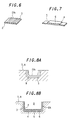
- the sponge silicone rubber material 12 is sheeted on an insulative protective rubber sheet 11 by using an unillustrated calender roll to a predetermined thickness, and subsequently cutting it into a predetermined width and length (see FIG. 9).
- the insulative protective rubber sheet 11 is molded by adding and mixing a predetermined vulcanizing agent in a silicone rubber compound to produce a sponge silicone rubber material 12, sheeting the sponge silicone rubber material 12 on an unillustrated base material sheet made from PET to a predetermined thickness by the calender roll, and heating and vulcanizing in an oven for a predetermined period of time.
- the silicone rubber material 12 a material obtained by adding and mixing a predetermined vulcanizing agent and a foaming agent in the silicone rubber compound is used.
- the laminated foam 10 is produced in this manner. Then, the laminated foam 10 is inserted upside down into an inner floor of the insulative rubber sheet 2A3 via a gap. At this time, the protective rubber sheet 11 of the laminated foam 10 is oriented to the opening direction of the insulative rubber sheet 2A3 (in the upper direction in FIG. 10A).
- a molding cope 13 is clamped against the molding drag 8 and heated under pressing, a sponge silicone material 12 of the laminated foam 10 is foamed and molded into an insulative foam elastomer 15, while the insulative foam elastomer 15 and the inner peripheral face of the insulative rubber sheet 2A3, and the insulative foam elastomer 15 and the protective rubber sheet 11 are integrally molded respectively.
- an electrical interconnector article 17A is formed, wherein the both end faces are formed as insulative exposed faces 15A, and the protective rubber sheet 11 is provided in a buried condition on the remaining part of the periphery of the insulative foam elastomer 15 on the same level, and a part thereof is exposed.
- the die 7 is opened to take out the electrical interconnector article 17A, and subjecting the electrical interconnector article 17A to post curing (secondary vulcanization) under predetermined conditions, to thereby form a long bar-shaped electrical interconnector article 17A (see FIG. 11A). Thereafter, the electrical interconnector article 17A is cut into a predetermined size and length, to thereby produce the electrical interconnector article 17A in a single number or plural numbers (see FIG. 12A).
- the other parts are the same as the conventional example, therefore the description thereof is omitted.
- a sheet laminate 4 is produced.
- a silicone rubber material 6 on a long base material sheet 5 made from PET, using an unillustrated calender roll, cutting it to a predetermined size, to obtain a sheet laminate 4 shown in FIG. 7.
- the silicone rubber material 6 a material obtained by adding and mixing a predetermined silicone rubber compound and a vulcanizing agent is used.
- the sheet laminate 4 is received in the bottom of the molding space 9 of the molding drag 8 constituting the die 7 to arrange the silicone rubber material 6 to face upward, and bend the insulative rubber sheet 2A3 roughly in a U shape in section with the plurality of conductive threads 3 exposed outside to thereby be received therein and intimately fitted thereto.
- the plurality of conductive threads 3 are brought into contact with the silicone rubber material 6 of the sheet laminate 4, and having the plurality of conductive threads 3 of the insulative rubber sheet 2A3 face to the molded face of the molding space 9 and intimately contact therewith.
- the laminated foam 10 is inserted upside down into an inner floor of the insulative rubber sheet 2A3 via a gap.
- the insulative protective rubber sheet 11 of the laminated foam 10 is oriented to the opening direction of the insulative rubber sheet 2A3 (in the upper direction in FIG. 10B).
- a molding cope 13 is clamped against the molding drag 8 and heated under pressing, the silicone rubber material 6 and the plurality of conductive threads 3 are bonded to form the silicone rubber material 6 into a deformation-restraining rubber sheet 14.
- a sponge silicone material 12 of the laminated foam 10 is foamed into an insulative foam elastomer 15, while the inner peripheral face of the insulative rubber sheet 2A3 and the insulative foam elastomer 15, and the insulative foam elastomer 15 and the insulative protective rubber sheet 11 are integrally molded respectively.
- an electrical interconnector intermediate body 16 is formed, wherein the both end faces 15A are formed as insulative exposed faces, the deformation-restraining rubber sheet 14 is exposed and the insulative protective rubber sheet 11 is provided in a buried condition on the other side of the insulative foam elastomer 15 on the same level, and a part thereof is exposed.
- the die 7 is opened to take out the electrical interconnector intermediate body 16 and the base material sheet 5 of the sheet laminate 4 is peeled off and removed, and the electrical interconnector intermediate body 16 is subjected to post curing (secondary vulcanization) under predetermined conditions, to thereby form a long bar-shaped electrical interconnector intermediate body 16 (see FIG. 11B).
- the electrical interconnector intermediate body 16 is cut into a predetermined size and length in the longitudinal direction by means of a cutter or the like, to thereby produce the press-contact electrical interconnector 17 in a single number or plural numbers (see FIG. 12B).
- the planar insulative protective rubber sheet 11 containing fillers in a large amount is provided in a buried condition on the other side on the periphery of the insulative foam elastomer 15, in other words, at a place where the plurality of conductive threads 3 do not exist, on the same level, and a part thereof is exposed.
- the tack effect is weakened due to the roughness on the surface of the insulative protective rubber sheet 11.
- the slip property is distinguishably improved, it hardly sticks, and even if the height of the electrical interconnector 17 is high, the assembling workability can be greatly improved, as well as the interconnection between the electronic circuit board and the subject electrical interconnector is really stabilized, hence reliable interconnection can be expected. Moreover, it becomes possible to greatly improve the initial contact property. Hence, non-interconnection between the electronic circuit board and the subject electronic circuit board can be effectively prevented, enabling stabilization of the quality.
- the deformation-restraining rubber sheet 14 adhered and secured at a position which is not involved in the interconnection between the electronic circuit board and the subject electronic circuit board restricts the flexure and deformation of the conductive threads 3 and the electrical interconnector 27, hence, even if the conductive threads 3 are pressed with a small force, the conductive threads 3 are not easily deformed, enabling suppression of defective ratio of products such as mobile phones. Moreover, even if a small force is applied, the surface of the electrical interconnector 17 is not easily deformed, hence the interconnection between the electronic circuit board and the subject electronic circuit board is truly stabilized, and great improvement of the assembling workability and handling easiness can also be expected.
- the deformation-restraining rubber sheet 14 is molded in a thickness of from 0.05 mm to 0.5 mm, the electrical interconnector 17 does not become large, and the electrode design of the electronic circuit board and the subject electronic circuit board is not adversely affected.
- the insulative foam elastomer 15 having roughly a rectangular section is shown, but the present invention is not limited to this shape, and an insulative foam elastomer 15 of a similar shape in section, such as a half oblong shape may be used.
- the insulative foam elastomer 15 may be exposed in a state that the insulative protective rubber sheet 11 is slightly projected from the other side of the periphery of the insulative foam elastomer 15.
- the number, the size, the shape or the like of the deformation-restraining rubber sheet 14 can be properly increased/decreased or varied.
- a plurality of conductive threads 3 may be disposed in parallel on the surface of the insulative rubber sheet 2A by means of gradually moving the rotary drum at a certain speed.
- the laminated foam 10 may be produced in advance prior to molding.
- a long base material sheet 1 consisting of a PET sheet having a thickness of 50 ⁇ m and a width of 350 mm, being a non-contractable base material, was first prepared.
- a silicone rubber material 2 was prepared by adding and mixing the vulcanizing agents C-19A, B (product name, produced by Shin-Etsu Kagaku Kogyo) in an amount of 0.5 and 0.25 part by weight, respectively, and 1.0 part by weight of a silane coupling agent KBM403 (above-mentioned) into 100 parts by weight of a silicone rubber compound KE-153U (above-mentioned) having a rubber hardness of 50°H.
- the silicone rubber material 2 was sheeted onto the base material sheet 1 by an unillustrated calender roll, so that it has a thickness of 100 ⁇ m and a width of 300 mm, to thereby form an insulative rubber sheet 2A.
- the insulative rubber sheet 2A was cut into a 600 mm length, which was then fixed on the periphery of the rotary drum having a circumference of 600 mm so that the insulative rubber sheet 2A became outside, and conductive threads 3 consisting of a gold-plated brass thread having a diameter of 40 ⁇ m were supplied from a feed apparatus onto the rotating rotary drum.
- This operation was repeated to dispose a plurality of conductive threads 3 on the entire periphery of the insulative rubber sheet 2A, and at the time of completion of disposition thereof, the rotation of the rotary drum was stopped and the insulative rubber sheet 2A with the conductive threads were removed from the rotary drum, and the conductive threads 3 on the 0.4 mm shifted position was removed to thereby form an insulative rubber sheet 2A1 shown in FIG. 4.
- the insulative rubber sheet 2A2 was heated in an oven at 120°C for 30 minutes to effect the primary vulcanization, the base material sheet 1 was peeled off and removed, and then the insulative rubber sheet 2A2 was heated again in an oven at 195°C for 4 hours to effect the secondary vulcanization, to thereby obtain the insulative rubber sheet 2A2 shown in FIG. 5.
- the insulative rubber sheet 2A2 was cut in the direction across the conductive threads 3 to produce an insulative rubber sheet 2A3 having a width of 8.0 mm and a length of 300 mm (see FIG. 6).
- the insulative rubber sheet 2A3 was set in the molding drag 8 having a molding space 9 in a U shape with the conductive threads 3 of the insulative rubber sheet 2A3 facing the molding face.
- a silicone rubber material was prepared by adding and mixing vulcanizing agents C-19A, C-198 (product name, produced by Shin-Etsu Kagaku Kogyo) in an amount of 0.3 and 2.5 part by weight, respectively, into 100 parts by weight of a silicone rubber compound KE-981 (above-mentioned) having a rubber hardness 80°H.
- This silicone rubber material was sheeted by a calender roll, and heated in an oven at 300°C for 1 minute to effect vulcanization, to thereby form a protective rubber sheet 11 having a thickness of 10 ⁇ m.
- vulcanizing agents C-1, C3 (product name, produced by Shin-Etsu Kagaku Kogyo) in an amount of 0.5 and 2.0 parts by weight, respectively, and 1.8 parts by weight of a foaming agent 2,2-azobis-isobutylnitrile were added and mixed into 100 parts by weight of a silicone rubber compound KE-151U (above-mentioned), to thereby prepare a sponge silicone rubber material 12.
- the sponge silicone rubber material 12 was sheeted onto the protective rubber sheet 8 in a thickness of 1.8 ⁇ m to prepare a laminate, which was cut in a size of 3 mm in height, 1.9 mm in width and 300 mm in length to prepare a laminated foam 10 (see FIG. 9). Then, the laminated foam 10 was placed on the inner floor of the insulative rubber sheet 2A3 as shown in FIG. 10A.
- the molding cope 13 was put on the molding drag 8 and clamped, then they were heated at 175°C for 5 minutes under a pressing load of 10 kg/cm 2 , to foam and mold the sponge silicone rubber material 12, which was designated as the insulative foam elastomer 12 (see FIG. 10B).
- the electrical interconnector article 17A was taken out from the opened die 7, and subjected to the post curing at 200°C for 1 hour, to obtain a long electrical interconnector article 17A shown in FIG. 11A. Thereafter, the electrical interconnector article 17A was cut at the 0.4 mm shifted position where the conductive threads 3 were not disposed and the insulative rubber sheet 2A3 was exposed (preferably cut at the central portion of the shifted position), to thereby prepare the electrical interconnector 17 having a length of 10.4 mm, a height of 4 mm and a width of 2 mm.
- the obtained electrical interconnector 17 had excellent workability even if the height was large. Moreover, there was no such a problem that an interconnection between a liquid crystal display and the circuit board or between electronic circuit boards could not be obtained because a predetermined contact of the electrical interconnector 17 pressing against the electronic circuit board and the subject electronic circuit board could not be obtained. Moreover, non-interconnection of a circuit was not caused.
- a long base material sheet 5 consisting of a PET sheet having a thickness of 50 ⁇ m and a width of 350 mm, being a non-contractable base material, was prepared.
- a silicone rubber material 6 was prepared by adding and mixing vulcanizing agents C-19A, B (product name, produced by Shinetsu Kagaku Kogyo) in an amount of 0.3 and 2.5 parts by weight, respectively, into 100 parts by weight of a silicone rubber compound KE-981 (above-mentioned) having a rubber hardness of 80°H.
- the silicone rubber material 6 was sheeted onto the base material sheet 5 by an unillustrated calender roll, so that it has a width of 4.0 mm and a length of 300 mm to thereby form a sheet laminate 4 (see FIG. 7).
- the sheet laminate 4 was received and arranged in the molding drag 8 having a molding space 9 in a U shape, and set so that the conductive threads 3 side of the insulative rubber sheet 2A3 faces the molding face.
- the vulcanizing agents C-19A, C-19B product name, produced by Shinetsu Kagaku Kogyo
- a silicone rubber compound KE-981 above-mentioned
- this silicone rubber material was sheeted by a calender roll, and heated and vulcanized in an oven at 300°C for 1 minute, to thereby form an insulative protective rubber sheet 11 having a thickness of 10 ⁇ m.
- vulcanizing agents C-1, C3 (product name, produced by Shin-Etsu Kagaku Kogyo) in an amount of 0.5 and 2.0 parts by weight, respectively, and 1.8 parts by weight of a foaming agent 2,2-azobis-isobutylnitrile were added and mixed into 100 parts by weight of a silicone rubber compound KE-151U (above-mentioned), to thereby prepare a sponge silicone rubber material 12.
- the sponge silicone rubber material 12 was sheeted onto the insulative protective rubber sheet 11 in a thickness of 1.8 ⁇ m to prepare a laminate, which was cut in a size of 3 mm in height, 1.9 mm in width and 300 mm in length to prepare a laminated foam 10 (see FIG. 9). Then, the laminated foam 10 was placed on the inner floor of the insulative rubber sheet 2A3 as shown in FIG. 10C.
- the molding cope 13 was put on the molding drag 8 and clamped, then they were heated at 175°C for 5 minutes under a pressing load of 10 kg/cm 2 , to foam and mold the sponge silicone rubber material 12, which was designated as the insulative foam elastomer 15 (see FIG. 11B).
- the electrical interconnector intermediate body 16 was taken out from the opened die 7, the base material sheet 5 of the sheet laminate 4 was peeled off, and the electrical interconnector intermediate body 16 was subjected to the post curing at 200°C for 1 hour, to obtain a long electrical interconnector intermediate body 16 shown in FIG. 11B. Thereafter, the electrical interconnector intermediate body 16 was cut at the 0.4 mm shifted position where the conductive threads 3 were not disposed and the insulative rubber sheet 2A3 was exposed (preferably cut at the central portion of the shifted position), to thereby prepare the electrical interconnector 17 shown in FIG. 12.
- the obtained electrical interconnector 17 did not deform at all even if a small force was applied to the spot where the deformation-restraining rubber sheet 14 existed. Moreover, even if the height was large, the workability was excellent. Furthermore, there was no such a problem that an interconnection between a liquid crystal display and a circuit board or between electronic circuit boards could not be obtained because a predetermined contact of the electrical interconnector 17 by pressing against the electronic circuit board and the subject electronic circuit board could not be obtained. Moreover, non-interconnection of a circuit was not caused.
- the slip property is improved, it hardly sticks, and even if the height of the electrical interconnector is large, the assembling workability can be improved, as well as the interconnection between the electronic circuit board and the subject electrical interconnector is stabilized, hence reliable interconnection can be expected.
- non-interconnection between an electrical joiner and an object to be electrically interconnected can be eliminated, enabling the quality to be stabilized.
- the tacking effect is weakened, a partial deformation of the electrical interconnector can be effectively prevented.
- the both end faces of the insulative foam elastomer are formed as the insulative exposed face, respectively, burrs due to the conductive threads are not caused, hence the insulated state can be maintained.
Landscapes
- Engineering & Computer Science (AREA)
- Manufacturing & Machinery (AREA)
- Coupling Device And Connection With Printed Circuit (AREA)
- Push-Button Switches (AREA)
- Manufacture Of Switches (AREA)
- Laminated Bodies (AREA)
- Manufacturing Of Electrical Connectors (AREA)
- Measuring Leads Or Probes (AREA)
- Shielding Devices Or Components To Electric Or Magnetic Fields (AREA)
Claims (4)
- Interconnecteur électrique du type à contact par pression (17) pour interconnecter un branchement électrique et un objet à interconnecter électriquement et étant situé entre le branchement électrique et l'objet à interconnecter électriquement, dans lequel :ledit interconnecteur électrique comprend une mousse d'élastomère isolante (15) en forme de colonne présentant un profil sensiblement en forme de U et une pluralité de conducteurs (3) sensiblement en forme de U et juxtaposés à intervalles sensiblement égaux en direction de et à partir d'une surface d'extrémité à l'autre surface d'extrémité de la mousse d'élastomère isolante ;les deux surfaces d'extrémité de la mousse d'élastomère isolante présentant la forme d'une surface isolante découverte, respectivement, caractérisé en ce qu'une feuille de caoutchouc isolante (2A) présentant un profil sensiblement en forme de U couvre la partie en forme de U de la périphérie de la mousse d'élastomère isolante (15) et une feuille de caoutchouc isolante (11) de grande dureté étant disposée à découvert sur la partie restante de la périphérie de la mousse d'élastomère isolante (15), les conducteurs étant formés en tant que fils conducteurs (3) sur la surface de la feuille de caoutchouc isolante (2A).
- Interconnecteur électrique du type à contact par pression selon la revendication 1, caractérisé en ce que la pluralité des fils conducteurs (3) se trouvant sur l'un des côtés de la feuille de caoutchouc isolante (2A) est pourvue d'une feuille de caoutchouc rétentrice de déformation (14) d'une grande dureté.
- Procédé de fabrication d'un interconnecteur électrique du type à contact par pression (17) pour interconnecter un branchement électrique et un objet à interconnecter électriquement par des fils- conducteurs, en étant situé entre le branchement électrique et l'objet à interconnecter électriquement, utilisant une feuille de caoutchouc isolante (2A) présentant une pluralité de fils conducteurs mutuellement parallèles placés sur la surface de celle-ci, un moule présentant un espace de moulage dont le profil est sensiblement en forme de U et une mousse laminée obtenue par laminage d'une feuille de caoutchouc protectrice isolante (11) de grande dureté et une substance de mousse d'élastomère (15), comprenant :un processus de réception de la feuille de caoutchouc isolante (2A) dans un profil sensiblement en forme de U dans l'espace de moulage du moule, d'orientation de la direction de la pluralité de fils conducteurs vers la surface de moulage de l'espace de moulage, et d'insertion de la mousse laminée dans la feuille de caoutchouc isolante avec la feuille de caoutchouc protectrice (11) faisant face à l'ouverture de la feuille de caoutchouc isolante ;un processus de serrage, de chauffage et de mise sous pression du moule pour faire mousser et mouler la substance d'élastomère de la mousse laminée tout en intégrant la mousse d'élastomère isolante, la feuille de caoutchouc isolante et la feuille de caoutchouc protectrice, pour ainsi mouler un élément moulé d'interconnecteur électrique dans lequel la feuille de caoutchouc protectrice est à découvert sur la partie restante de la périphérie de la mousse d'élastomère isolante etun processus de sectionnement d'une longueur prédéterminée de l'élément moulé d'interconnecteur électrique retiré du moule ouvert.
- Procédé selon la revendication 3, caractérisé par l'utilisation en outre d'une feuille laminée obtenue en pourvoyant une feuille de caoutchouc rétentrice de déformation qui est d'une grande dureté et non vulcanisée sur la feuille de la substance de base, comprenant en outre :un processus de réception de la feuille laminée dans l'espace de moulage du moule, ainsi que de réception de la feuille de caoutchouc isolante présentant la pluralité de fils conducteurs découverts à l'extérieur, en la courbant en un profil sensiblement en forme de U, pour amener ainsi la pluralité des fils conducteurs au fond de la feuille de caoutchouc isolante, en contact avec la feuille de caoutchouc rétentrice de déformation de la feuille laminée et insérer la mousse laminée dans la feuille de caoutchouc isolante avec la feuille de caoutchouc protectrice isolante faisant face vers l'ouverture de la feuille de caoutchouc isolante ;un processus de serrage, de chauffage et de mise sous pression du moule pour faire adhérer la feuille de caoutchouc rétentrice de déformation de la feuille laminée et la pluralité de fils conducteurs au fond de la feuille de caoutchouc isolante, la substance moussante d'élastomère isolante de la mousse laminée pour former la mousse d'élastomère, etun processus d'enlèvement de la feuille de substance de base de la feuille laminée, en prélevant le corps intermédiaire de l'interconnecteur électrique.
Applications Claiming Priority (4)
| Application Number | Priority Date | Filing Date | Title |
|---|---|---|---|
| JP01354499A JP3318278B2 (ja) | 1999-01-21 | 1999-01-21 | 圧接型の電気コネクタ及びその製造方法 |
| JP1354499 | 1999-01-21 | ||
| JP02648899A JP3531724B2 (ja) | 1999-02-03 | 1999-02-03 | 圧接型の電気コネクタ及びその製造方法 |
| JP2648899 | 1999-02-03 |
Publications (2)
| Publication Number | Publication Date |
|---|---|
| EP1022811A1 EP1022811A1 (fr) | 2000-07-26 |
| EP1022811B1 true EP1022811B1 (fr) | 2002-05-02 |
Family
ID=26349363
Family Applications (1)
| Application Number | Title | Priority Date | Filing Date |
|---|---|---|---|
| EP00100607A Expired - Lifetime EP1022811B1 (fr) | 1999-01-21 | 2000-01-13 | Interconnecteur électrique du type à contact par pression et méthode de sa fabrication |
Country Status (8)
| Country | Link |
|---|---|
| US (1) | US6241533B1 (fr) |
| EP (1) | EP1022811B1 (fr) |
| KR (1) | KR100614718B1 (fr) |
| CN (1) | CN1149722C (fr) |
| AT (1) | ATE217124T1 (fr) |
| DE (1) | DE60000139T2 (fr) |
| NO (1) | NO317924B1 (fr) |
| TW (1) | TW445680B (fr) |
Families Citing this family (17)
| Publication number | Priority date | Publication date | Assignee | Title |
|---|---|---|---|---|
| US6362435B1 (en) * | 1999-12-20 | 2002-03-26 | Delphi Technologies, Inc. | Multi-layer conductor pad for reducing solder voiding |
| US20040114773A1 (en) * | 2002-12-17 | 2004-06-17 | Jensen James M. | Assembly for making an electrical connection between components |
| EP1507317A1 (fr) * | 2003-08-11 | 2005-02-16 | Hirschmann Electronics GmbH & Co. KG | Connecteur élastique |
| ITTO20030846A1 (it) * | 2003-10-28 | 2005-04-29 | Intier Automotive Closures Spa | Procedimento per la realizzazione di un corpo di supporto per una serratura di un autoveicolo e corpo di supporto cosi' ottenuto. |
| IL174146A0 (en) * | 2005-03-11 | 2006-08-01 | Thomas & Betts Int | Coaxial connector with a cable gripping feature |
| JP4179620B2 (ja) * | 2005-04-28 | 2008-11-12 | 日本航空電子工業株式会社 | コネクタ |
| US7070420B1 (en) * | 2005-08-08 | 2006-07-04 | Wakefield Steven B | Electrical interconnect system utilizing nonconductive elastomeric elements and continuous conductive elements |
| JP4286266B2 (ja) * | 2006-03-31 | 2009-06-24 | 日本航空電子工業株式会社 | コネクタ |
| CN100364181C (zh) * | 2006-04-03 | 2008-01-23 | 镇江红宝利电子有限公司 | 射频同轴插针连接器 |
| TWI346425B (en) * | 2006-05-30 | 2011-08-01 | Fujikura Ltd | Socket contact terminal and semiconductor apparatus |
| JP4913522B2 (ja) * | 2006-09-29 | 2012-04-11 | 北陸電気工業株式会社 | 回路基板相互接続用コネクタ装置 |
| JP2008277113A (ja) * | 2007-04-27 | 2008-11-13 | Japan Aviation Electronics Industry Ltd | コネクタ |
| US7768280B1 (en) * | 2007-11-15 | 2010-08-03 | Altera Corporation | Apparatus for a low-cost semiconductor test interface system |
| JP2009146666A (ja) * | 2007-12-12 | 2009-07-02 | Japan Aviation Electronics Industry Ltd | コネクタ |
| US10559902B2 (en) | 2016-01-04 | 2020-02-11 | International Business Machines Corporation | Electrical connection management using a card |
| US9515401B1 (en) * | 2016-01-04 | 2016-12-06 | International Business Machines Corporation | Elastomeric electrical connector structure joining two hardware planes at right angles to each other |
| DE102017217334B3 (de) * | 2017-09-28 | 2019-03-21 | Joyson Safety Systems Germany Gmbh | Kontaktierungsanordnung und Lenkrad mit einer solchen Kontaktierungsanordnung |
Family Cites Families (12)
| Publication number | Priority date | Publication date | Assignee | Title |
|---|---|---|---|---|
| DE2234960C3 (de) * | 1971-11-26 | 1975-04-30 | Teledyne, Inc., Los Angeles, Calif. (V.St.A.) | Elektrischer Stecker |
| US3998512A (en) * | 1975-02-13 | 1976-12-21 | International Telephone And Telegraph Corporation | Electrical connector |
| US4008938A (en) * | 1975-08-11 | 1977-02-22 | International Telephone And Telegraph Corporation | Electrical connector |
| AU516166B2 (en) * | 1977-09-24 | 1981-05-21 | Amp Incorporated | Electrical connector |
| US4720269A (en) * | 1987-03-10 | 1988-01-19 | Northern Telecom Limited | Modular telephone jack with elastomeric contact member |
| US4815979A (en) * | 1987-12-23 | 1989-03-28 | Ncr Corporation | Right angle electrical connector with or without wiping action |
| US4973256A (en) * | 1989-08-18 | 1990-11-27 | Texas Instruments Incorporated | Device under test interface board and test electronic card interconnection in semiconductor test system |
| JP2796872B2 (ja) | 1990-03-30 | 1998-09-10 | キヤノン株式会社 | 電気的接続部材の製造方法 |
| JPH04105174A (ja) | 1990-08-24 | 1992-04-07 | Toshiba Corp | システム設計装置 |
| US5259770A (en) * | 1992-03-19 | 1993-11-09 | Amp Incorporated | Impedance controlled elastomeric connector |
| DE19605661A1 (de) * | 1995-02-24 | 1996-08-29 | Whitaker Corp | Elektrisches Verbinderbauteil zur Herstellung einer elektrischen Verbindung zwischen leitfähigen Flächen |
| JP3640268B2 (ja) | 1995-10-06 | 2005-04-20 | ザ ウィタカー コーポレーション | コネクタ及びコネクタ製造方法 |
-
1999
- 1999-12-30 TW TW088123294A patent/TW445680B/zh not_active IP Right Cessation
-
2000
- 2000-01-10 NO NO20000131A patent/NO317924B1/no not_active IP Right Cessation
- 2000-01-13 EP EP00100607A patent/EP1022811B1/fr not_active Expired - Lifetime
- 2000-01-13 DE DE60000139T patent/DE60000139T2/de not_active Expired - Fee Related
- 2000-01-13 AT AT00100607T patent/ATE217124T1/de not_active IP Right Cessation
- 2000-01-18 KR KR1020000002131A patent/KR100614718B1/ko not_active Expired - Lifetime
- 2000-01-18 US US09/483,910 patent/US6241533B1/en not_active Expired - Lifetime
- 2000-01-21 CN CNB001011499A patent/CN1149722C/zh not_active Expired - Fee Related
Also Published As
| Publication number | Publication date |
|---|---|
| CN1149722C (zh) | 2004-05-12 |
| NO317924B1 (no) | 2005-01-10 |
| CN1262537A (zh) | 2000-08-09 |
| TW445680B (en) | 2001-07-11 |
| EP1022811A1 (fr) | 2000-07-26 |
| NO20000131D0 (no) | 2000-01-10 |
| US6241533B1 (en) | 2001-06-05 |
| KR20000071258A (ko) | 2000-11-25 |
| DE60000139D1 (de) | 2002-06-06 |
| DE60000139T2 (de) | 2002-11-28 |
| KR100614718B1 (ko) | 2006-08-21 |
| NO20000131L (no) | 2000-07-24 |
| ATE217124T1 (de) | 2002-05-15 |
Similar Documents
| Publication | Publication Date | Title |
|---|---|---|
| EP1022811B1 (fr) | Interconnecteur électrique du type à contact par pression et méthode de sa fabrication | |
| US5403194A (en) | Elastic interconnector | |
| JP2602623B2 (ja) | Icソケット | |
| JPH0334194B2 (fr) | ||
| EP0626702B1 (fr) | Câble plat | |
| CN100550519C (zh) | 柔软性良导电层、各向异性导电片及其制造方法 | |
| JP2876292B2 (ja) | コネクタおよびコネクタの製造方法 | |
| JPH0997643A (ja) | 低抵抗コネクタと、その製造方法 | |
| JP2001291571A (ja) | 導電部材及びその製造方法 | |
| JP3531724B2 (ja) | 圧接型の電気コネクタ及びその製造方法 | |
| EP2720525A1 (fr) | Joint d'étanchéité à montage de surface et son procédé de fabrication | |
| JP3318278B2 (ja) | 圧接型の電気コネクタ及びその製造方法 | |
| JP3202956B2 (ja) | 圧接型コネクタ | |
| JP4024029B2 (ja) | 圧接型コネクタの製造方法 | |
| JPH11191454A (ja) | 圧接型コネクタの製造方法 | |
| JPH1197125A (ja) | 円柱コネクタおよびその製造方法 | |
| US20040082207A1 (en) | Anisotropic conductive elastic connector | |
| JPH06160215A (ja) | 圧力センサおよびその製造方法 | |
| JPH04116374U (ja) | 弾性コネクター | |
| JP3544306B2 (ja) | 圧接型コネクタ | |
| JP3361253B2 (ja) | コンデンサマイクロフォンの接続方法、接続構造 | |
| JPH0734561U (ja) | エラスチックコネクタ | |
| JP2003017158A (ja) | 圧接型シートコネクタ及びその製造方法 | |
| JP2002008814A (ja) | 圧接型コネクタの製造方法 | |
| JP3202959B2 (ja) | 導電部材及びこれを用いてなる低抵抗コネクタ |
Legal Events
| Date | Code | Title | Description |
|---|---|---|---|
| PUAI | Public reference made under article 153(3) epc to a published international application that has entered the european phase |
Free format text: ORIGINAL CODE: 0009012 |
|
| AK | Designated contracting states |
Kind code of ref document: A1 Designated state(s): AT BE CH CY DE DK ES FI FR GB GR IE IT LI LU MC NL PT SE |
|
| AX | Request for extension of the european patent |
Free format text: AL;LT;LV;MK;RO;SI |
|
| 17P | Request for examination filed |
Effective date: 20000902 |
|
| 17Q | First examination report despatched |
Effective date: 20001116 |
|
| AKX | Designation fees paid |
Free format text: AT BE CH CY DE DK ES FI FR GB GR IE IT LI LU MC NL PT SE |
|
| GRAG | Despatch of communication of intention to grant |
Free format text: ORIGINAL CODE: EPIDOS AGRA |
|
| GRAG | Despatch of communication of intention to grant |
Free format text: ORIGINAL CODE: EPIDOS AGRA |
|
| GRAH | Despatch of communication of intention to grant a patent |
Free format text: ORIGINAL CODE: EPIDOS IGRA |
|
| REG | Reference to a national code |
Ref country code: GB Ref legal event code: IF02 |
|
| GRAH | Despatch of communication of intention to grant a patent |
Free format text: ORIGINAL CODE: EPIDOS IGRA |
|
| GRAA | (expected) grant |
Free format text: ORIGINAL CODE: 0009210 |
|
| AK | Designated contracting states |
Kind code of ref document: B1 Designated state(s): AT BE CH CY DE DK ES FI FR GB GR IE IT LI LU MC NL PT SE |
|
| PG25 | Lapsed in a contracting state [announced via postgrant information from national office to epo] |
Ref country code: CH Free format text: LAPSE BECAUSE OF FAILURE TO SUBMIT A TRANSLATION OF THE DESCRIPTION OR TO PAY THE FEE WITHIN THE PRESCRIBED TIME-LIMIT Effective date: 20020502 Ref country code: AT Free format text: LAPSE BECAUSE OF FAILURE TO SUBMIT A TRANSLATION OF THE DESCRIPTION OR TO PAY THE FEE WITHIN THE PRESCRIBED TIME-LIMIT Effective date: 20020502 Ref country code: GR Free format text: LAPSE BECAUSE OF FAILURE TO SUBMIT A TRANSLATION OF THE DESCRIPTION OR TO PAY THE FEE WITHIN THE PRESCRIBED TIME-LIMIT Effective date: 20020502 Ref country code: BE Free format text: LAPSE BECAUSE OF FAILURE TO SUBMIT A TRANSLATION OF THE DESCRIPTION OR TO PAY THE FEE WITHIN THE PRESCRIBED TIME-LIMIT Effective date: 20020502 Ref country code: LI Free format text: LAPSE BECAUSE OF FAILURE TO SUBMIT A TRANSLATION OF THE DESCRIPTION OR TO PAY THE FEE WITHIN THE PRESCRIBED TIME-LIMIT Effective date: 20020502 |
|
| REF | Corresponds to: |
Ref document number: 217124 Country of ref document: AT Date of ref document: 20020515 Kind code of ref document: T |
|
| REG | Reference to a national code |
Ref country code: GB Ref legal event code: FG4D |
|
| REG | Reference to a national code |
Ref country code: CH Ref legal event code: EP |
|
| REF | Corresponds to: |
Ref document number: 60000139 Country of ref document: DE Date of ref document: 20020606 |
|
| REG | Reference to a national code |
Ref country code: IE Ref legal event code: FG4D |
|
| PG25 | Lapsed in a contracting state [announced via postgrant information from national office to epo] |
Ref country code: PT Free format text: LAPSE BECAUSE OF FAILURE TO SUBMIT A TRANSLATION OF THE DESCRIPTION OR TO PAY THE FEE WITHIN THE PRESCRIBED TIME-LIMIT Effective date: 20020802 Ref country code: DK Free format text: LAPSE BECAUSE OF FAILURE TO SUBMIT A TRANSLATION OF THE DESCRIPTION OR TO PAY THE FEE WITHIN THE PRESCRIBED TIME-LIMIT Effective date: 20020802 |
|
| ET | Fr: translation filed | ||
| REG | Reference to a national code |
Ref country code: CH Ref legal event code: PL |
|
| PG25 | Lapsed in a contracting state [announced via postgrant information from national office to epo] |
Ref country code: ES Free format text: LAPSE BECAUSE OF FAILURE TO SUBMIT A TRANSLATION OF THE DESCRIPTION OR TO PAY THE FEE WITHIN THE PRESCRIBED TIME-LIMIT Effective date: 20021128 |
|
| PG25 | Lapsed in a contracting state [announced via postgrant information from national office to epo] |
Ref country code: LU Free format text: LAPSE BECAUSE OF NON-PAYMENT OF DUE FEES Effective date: 20030113 Ref country code: IE Free format text: LAPSE BECAUSE OF NON-PAYMENT OF DUE FEES Effective date: 20030113 Ref country code: CY Free format text: LAPSE BECAUSE OF FAILURE TO SUBMIT A TRANSLATION OF THE DESCRIPTION OR TO PAY THE FEE WITHIN THE PRESCRIBED TIME-LIMIT Effective date: 20030113 |
|
| PG25 | Lapsed in a contracting state [announced via postgrant information from national office to epo] |
Ref country code: MC Free format text: LAPSE BECAUSE OF NON-PAYMENT OF DUE FEES Effective date: 20030131 |
|
| PLBE | No opposition filed within time limit |
Free format text: ORIGINAL CODE: 0009261 |
|
| STAA | Information on the status of an ep patent application or granted ep patent |
Free format text: STATUS: NO OPPOSITION FILED WITHIN TIME LIMIT |
|
| 26N | No opposition filed |
Effective date: 20030204 |
|
| REG | Reference to a national code |
Ref country code: IE Ref legal event code: MM4A |
|
| PGFP | Annual fee paid to national office [announced via postgrant information from national office to epo] |
Ref country code: FI Payment date: 20090114 Year of fee payment: 10 Ref country code: NL Payment date: 20090115 Year of fee payment: 10 Ref country code: DE Payment date: 20090108 Year of fee payment: 10 |
|
| PGFP | Annual fee paid to national office [announced via postgrant information from national office to epo] |
Ref country code: GB Payment date: 20090107 Year of fee payment: 10 |
|
| PGFP | Annual fee paid to national office [announced via postgrant information from national office to epo] |
Ref country code: IT Payment date: 20090129 Year of fee payment: 10 Ref country code: SE Payment date: 20090108 Year of fee payment: 10 |
|
| PGFP | Annual fee paid to national office [announced via postgrant information from national office to epo] |
Ref country code: FR Payment date: 20090113 Year of fee payment: 10 |
|
| REG | Reference to a national code |
Ref country code: NL Ref legal event code: V1 Effective date: 20100801 |
|
| GBPC | Gb: european patent ceased through non-payment of renewal fee |
Effective date: 20100113 |
|
| EUG | Se: european patent has lapsed | ||
| REG | Reference to a national code |
Ref country code: FR Ref legal event code: ST Effective date: 20100930 |
|
| PG25 | Lapsed in a contracting state [announced via postgrant information from national office to epo] |
Ref country code: NL Free format text: LAPSE BECAUSE OF NON-PAYMENT OF DUE FEES Effective date: 20100801 Ref country code: FR Free format text: LAPSE BECAUSE OF NON-PAYMENT OF DUE FEES Effective date: 20100201 |
|
| PG25 | Lapsed in a contracting state [announced via postgrant information from national office to epo] |
Ref country code: FI Free format text: LAPSE BECAUSE OF NON-PAYMENT OF DUE FEES Effective date: 20100113 Ref country code: DE Free format text: LAPSE BECAUSE OF NON-PAYMENT OF DUE FEES Effective date: 20100803 |
|
| PG25 | Lapsed in a contracting state [announced via postgrant information from national office to epo] |
Ref country code: GB Free format text: LAPSE BECAUSE OF NON-PAYMENT OF DUE FEES Effective date: 20100113 |
|
| PG25 | Lapsed in a contracting state [announced via postgrant information from national office to epo] |
Ref country code: IT Free format text: LAPSE BECAUSE OF NON-PAYMENT OF DUE FEES Effective date: 20100113 |
|
| PG25 | Lapsed in a contracting state [announced via postgrant information from national office to epo] |
Ref country code: SE Free format text: LAPSE BECAUSE OF NON-PAYMENT OF DUE FEES Effective date: 20100114 |