EP1024219A1 - Garn mit einer Teilfärbung auf einer Seite sowie Vorrichtung zum Färben, Trocknen und Aufwickeln eines Garns - Google Patents
Garn mit einer Teilfärbung auf einer Seite sowie Vorrichtung zum Färben, Trocknen und Aufwickeln eines Garns Download PDFInfo
- Publication number
- EP1024219A1 EP1024219A1 EP99101928A EP99101928A EP1024219A1 EP 1024219 A1 EP1024219 A1 EP 1024219A1 EP 99101928 A EP99101928 A EP 99101928A EP 99101928 A EP99101928 A EP 99101928A EP 1024219 A1 EP1024219 A1 EP 1024219A1
- Authority
- EP
- European Patent Office
- Prior art keywords
- yarn
- dye
- dye liquid
- raw material
- fibrous raw
- Prior art date
- Legal status (The legal status is an assumption and is not a legal conclusion. Google has not performed a legal analysis and makes no representation as to the accuracy of the status listed.)
- Withdrawn
Links
- 239000007788 liquid Substances 0.000 title claims abstract description 148
- 238000001035 drying Methods 0.000 title claims abstract description 23
- 239000002994 raw material Substances 0.000 claims abstract description 68
- 238000007602 hot air drying Methods 0.000 claims abstract description 21
- 238000010438 heat treatment Methods 0.000 claims abstract description 13
- 235000019646 color tone Nutrition 0.000 claims description 16
- 239000000463 material Substances 0.000 claims description 15
- 238000007664 blowing Methods 0.000 claims description 7
- 210000002268 wool Anatomy 0.000 claims description 5
- 238000002347 injection Methods 0.000 claims description 4
- 239000007924 injection Substances 0.000 claims description 4
- 238000007599 discharging Methods 0.000 claims description 2
- 238000004804 winding Methods 0.000 claims description 2
- XUXNAKZDHHEHPC-UHFFFAOYSA-M sodium bromate Chemical compound [Na+].[O-]Br(=O)=O XUXNAKZDHHEHPC-UHFFFAOYSA-M 0.000 claims 1
- 238000000034 method Methods 0.000 abstract description 15
- 238000004043 dyeing Methods 0.000 abstract description 13
- 239000000835 fiber Substances 0.000 abstract description 11
- 239000004744 fabric Substances 0.000 abstract description 6
- 238000007639 printing Methods 0.000 abstract description 3
- 239000012209 synthetic fiber Substances 0.000 abstract description 3
- 229920002994 synthetic fiber Polymers 0.000 abstract description 3
- 229920000742 Cotton Polymers 0.000 abstract description 2
- 238000009987 spinning Methods 0.000 abstract description 2
- 238000004519 manufacturing process Methods 0.000 abstract 1
- 238000003672 processing method Methods 0.000 abstract 1
- 239000000975 dye Substances 0.000 description 144
- 238000000889 atomisation Methods 0.000 description 6
- 239000001044 red dye Substances 0.000 description 4
- NIXOWILDQLNWCW-UHFFFAOYSA-N acrylic acid group Chemical group C(C=C)(=O)O NIXOWILDQLNWCW-UHFFFAOYSA-N 0.000 description 3
- 239000001045 blue dye Substances 0.000 description 3
- 239000000203 mixture Substances 0.000 description 3
- AJDUTMFFZHIJEM-UHFFFAOYSA-N n-(9,10-dioxoanthracen-1-yl)-4-[4-[[4-[4-[(9,10-dioxoanthracen-1-yl)carbamoyl]phenyl]phenyl]diazenyl]phenyl]benzamide Chemical compound O=C1C2=CC=CC=C2C(=O)C2=C1C=CC=C2NC(=O)C(C=C1)=CC=C1C(C=C1)=CC=C1N=NC(C=C1)=CC=C1C(C=C1)=CC=C1C(=O)NC1=CC=CC2=C1C(=O)C1=CC=CC=C1C2=O AJDUTMFFZHIJEM-UHFFFAOYSA-N 0.000 description 3
- 239000001043 yellow dye Substances 0.000 description 3
- 238000009825 accumulation Methods 0.000 description 2
- 239000003610 charcoal Substances 0.000 description 2
- 238000005516 engineering process Methods 0.000 description 2
- 238000009940 knitting Methods 0.000 description 2
- 238000009688 liquid atomisation Methods 0.000 description 2
- 230000015572 biosynthetic process Effects 0.000 description 1
- 239000003086 colorant Substances 0.000 description 1
- 238000004040 coloring Methods 0.000 description 1
- 230000000694 effects Effects 0.000 description 1
- 239000003292 glue Substances 0.000 description 1
- 210000004209 hair Anatomy 0.000 description 1
- 238000009975 hank dyeing Methods 0.000 description 1
- 229920000728 polyester Polymers 0.000 description 1
- 229910001220 stainless steel Inorganic materials 0.000 description 1
- 239000010935 stainless steel Substances 0.000 description 1
- 238000009970 yarn dyeing Methods 0.000 description 1
Images




Classifications
-
- D—TEXTILES; PAPER
- D06—TREATMENT OF TEXTILES OR THE LIKE; LAUNDERING; FLEXIBLE MATERIALS NOT OTHERWISE PROVIDED FOR
- D06B—TREATING TEXTILE MATERIALS USING LIQUIDS, GASES OR VAPOURS
- D06B1/00—Applying liquids, gases or vapours onto textile materials to effect treatment, e.g. washing, dyeing, bleaching, sizing or impregnating
- D06B1/10—Applying liquids, gases or vapours onto textile materials to effect treatment, e.g. washing, dyeing, bleaching, sizing or impregnating by contact with a member carrying the treating material
- D06B1/14—Applying liquids, gases or vapours onto textile materials to effect treatment, e.g. washing, dyeing, bleaching, sizing or impregnating by contact with a member carrying the treating material with a roller
- D06B1/141—Applying liquids, gases or vapours onto textile materials to effect treatment, e.g. washing, dyeing, bleaching, sizing or impregnating by contact with a member carrying the treating material with a roller where an element is used to mitigate the quantity of treating material on the roller
-
- D—TEXTILES; PAPER
- D06—TREATMENT OF TEXTILES OR THE LIKE; LAUNDERING; FLEXIBLE MATERIALS NOT OTHERWISE PROVIDED FOR
- D06B—TREATING TEXTILE MATERIALS USING LIQUIDS, GASES OR VAPOURS
- D06B1/00—Applying liquids, gases or vapours onto textile materials to effect treatment, e.g. washing, dyeing, bleaching, sizing or impregnating
- D06B1/02—Applying liquids, gases or vapours onto textile materials to effect treatment, e.g. washing, dyeing, bleaching, sizing or impregnating by spraying or projecting
-
- D—TEXTILES; PAPER
- D06—TREATMENT OF TEXTILES OR THE LIKE; LAUNDERING; FLEXIBLE MATERIALS NOT OTHERWISE PROVIDED FOR
- D06B—TREATING TEXTILE MATERIALS USING LIQUIDS, GASES OR VAPOURS
- D06B11/00—Treatment of selected parts of textile materials, e.g. partial dyeing
- D06B11/002—Treatment of selected parts of textile materials, e.g. partial dyeing of moving yarns
-
- D—TEXTILES; PAPER
- D06—TREATMENT OF TEXTILES OR THE LIKE; LAUNDERING; FLEXIBLE MATERIALS NOT OTHERWISE PROVIDED FOR
- D06B—TREATING TEXTILE MATERIALS USING LIQUIDS, GASES OR VAPOURS
- D06B21/00—Successive treatments of textile materials by liquids, gases or vapours
-
- D—TEXTILES; PAPER
- D06—TREATMENT OF TEXTILES OR THE LIKE; LAUNDERING; FLEXIBLE MATERIALS NOT OTHERWISE PROVIDED FOR
- D06B—TREATING TEXTILE MATERIALS USING LIQUIDS, GASES OR VAPOURS
- D06B1/00—Applying liquids, gases or vapours onto textile materials to effect treatment, e.g. washing, dyeing, bleaching, sizing or impregnating
- D06B1/10—Applying liquids, gases or vapours onto textile materials to effect treatment, e.g. washing, dyeing, bleaching, sizing or impregnating by contact with a member carrying the treating material
- D06B1/14—Applying liquids, gases or vapours onto textile materials to effect treatment, e.g. washing, dyeing, bleaching, sizing or impregnating by contact with a member carrying the treating material with a roller
Definitions
- This invention relates to a partial dyed yarn having a partial dye formation applied to a side surface of a fibrous raw material of which dyeing and processing in the prior art dye adhering method were difficult and further relates to a partial dye adhering at the side surface of a yarn capable of generating mixed feeling with deep color tone in a product or a taste of high class in the case that the yarn is applied in a fabric or a knitted product or the like and to a device for adhering dye liquid to, drying and taking-up the same.
- the prior art dye adhering method applied to various kinds of fibrous raw materials such as yarn-like natural fibers, animal fibers (wool, wild animal hairs, silk or the like), synthetic fibers, semisynthetic fibers or the like (hereinafter called as "fibrous raw materials") had an object to perform a dyeing operation in such a way that a uniform dye adhering state could be attained at a cross-sectional shape with the dye adhered yarn being cut like a ring, wherein a large amount of an entire dye adhering operation was carried out concurrently through a cone dye adhering operation or hank dyeing operation or the like.
- fibrous raw materials such as yarn-like natural fibers, animal fibers (wool, wild animal hairs, silk or the like), synthetic fibers, semisynthetic fibers or the like
- the melange yarn or the like in the prior art although it was defined as one in which a part of the raw material fiber such as a raw cotton or the like is dyed in advance, it is spinned under a state in which the raw material fibers having a plurality of colors are mixed to each other to show a color tone of melange yarn, such a process as above required as an essential requirement that its process passed through the spinning step, it took much amount of time in processing product and it could not fulfill the modern needs of increasing in processing speed so as to attain a new and unique color tone.
- the present invention improves the problems in the prior art dye adhering and processing operation and it is an object of the present invention to provide a partial dyed yarn, a method for adhering dye liquid and a device for adhering the dye liquid, drying it and taking-up the dye liquid in which a continuous fibrous raw material is passed through the dye liquid adhering roll to adhere the dye liquid to the material, thereafter it is merely applied with a heat treatment to perform a speedy color dyeing to a desired color tone and a higher class taste such as a deep color or mixed taste or the like than those of the prior art melange yarn can be generated.
- the present invention is carried out such that a part of the side surface of the optional continuous fibrous raw material spinned and processed is applied with dye partially in a continuous or intermittent manner, wherein the present invention provides a partial dye adhered yarn having a taste of high class grade producing a deep feeling or a mixed feeling dyed in speedy manner to an optional color tone in which the fibrous raw material is passed through the dye liquid adhering roll, thereby the dye liquid is adhered to the material and a heat treatment is applied to it.
- the present invention provides a dye liquid adhering, drying and taking-up device characterized in that the fibrous raw material is passed over a guide groove formed at an outer circumference of a dye liquid adhering roll at a desired yarn speed while a proper tension force is being applied to the material, the dye liquid adhering roll is properly rotated with its frictional force and at the same time the dye liquid is adhered to the side surface of the fibrous raw material in a continuous or intermittent manner while its adhering amount is being controlled, the adhered dye liquid is further dried while the material is being turned in the hot air drying device and passed and then the material is taken up as a dried cone.
- Fig.1 is an illustration for showing a dye liquid adhering, drying and taking-up device in accordance with a first preferred embodiment used in the present invention.
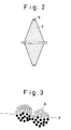
- Fig.2 is a side sectional view for showing a dye liquid adhering roller installed similarly in this dye liquid adhering, drying and taking-up device.
- Fig.3 is a cross sectional illustration for showing a fibrous bundle after dyeing attained by the first preferred embodiment.
- Fig.4 is an illustration for showing a second preferred embodiment of the dye liquid adhering, drying and taking-up device of the present invention and a state in which an air blowing pipe is arranged before a dye liquid adhering roller of the dye liquid adhering, drying and taking-up device in the first preferred embodiment.
- Fig.5 is an illustration for showing a chenille yarn after dyeing attained by a second preferred embodiment.
- Fig.6 is an illustration for showing a device for finishing a partial dyed yarn installed in a dye liquid adhering, drying and taking-up device of the second preferred embodiment.
- Fig.7 is similarly an outer appearance illustration for showing rotary drums.
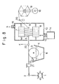
- Fig.8 is an illustration for showing a state in accordance with a third preferred embodiment of a dye liquid adhering, drying and taking-up device of the present invention and having a liquid adhering control device added thereto.
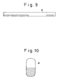
- Fig.9 is a side elevational view of a tape dyed in accordance with a third preferred embodiment.
- Fig.10 is similarly a cross sectional illustration for showing a dyed tape yarn.
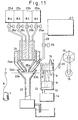
- Fig.11 is an illustration for showing a dye liquid adhering, drying and taking-up device related to a fourth preferred embodiment of the present invention and for use in adhering dye'liquid to a side surface of fibrous raw material of printed dye touch.
- Fig.12 is a sectional illustration for showing a dyed state in which a print is applied to a knitted product with partial dye yarn attained by the present preferred embodiment.
- Fig.13 is an illustration for showing a state in which a knitted product after dyeing in the preferred embodiment is rewound.
- Fig.1 illustrates a dye liquid adhering, drying and taking-up device of a first preferred embodiment used in the present invention
- Fig.2 is a side sectional view for showing a dye liquid adhering roller similarly installed in the dye liquid adhering, drying and taking-up device, wherein the raw material used in the preferred embodiment is described in reference to the case in which a double-yarn of wool No.48 wound like a cone 1 is applied as a supplied fibrous raw material A, although it is of course apparent that it is not necessarily restricted to the aforesaid double-yarn wool No.48.
- the dye liquid adhering, drying and taking-up device in the preferred embodiment is comprised of a dye liquid adhering roller 3 for adhering dye liquid B to a supplied fibrous raw material A passing through a guide 2 at a predetermined yarn speed; a dye liquid pan 4 arranged below the dye liquid adhering roller 3 and storing dye liquid B therein; rotary drums 7, 8 for immersing a part of a guiding groove 5 circumferentially formed at an outer circumference of the rotating dye liquid adhering roller 3 (refer to Fig.2), adhering the dye liquid B to it, thereafter winding the supplied fibrous raw material A adhered with the dye liquid B by an optional number of turns through a guide 6; a box type hot air drying device 12 for finishing the supplied fibrous raw material A it into a dried cone 11 while the raw material A is being taken up through a guide 9 toward a taking-up drum 10; a hot air generating device 14 for feeding hot air into the box type hot air drying device 12 through a hot air inlet port 13 (in
- the aforesaid guide 6, rotary drums 7, 8 and guide 9 are installed within the box type hot air drying device 12, wherein the drum 10 is applied with a rotating force by a driving device 16 such as a motor or the like, generates a predetermined tension force while taking up the supplied fiber A and further rotates the aforesaid dye liquid adhering roller 3 and the rotary drums 7, 8, respectively.
- the requisite amount of dye liquid B adhered to the guide groove 5 of the dye liquid adhering roller 3 is scraped off by a dye liquid adhering control device 17 contacted with the dye liquid adhering roller 3 and any surplus dye liquid B is not adhered to the supplied fibrous raw material A.
- this dye liquid adhering roller 3 is normally made of stainless steel, its material quality is changed to enable an amount of adhesion of dye liquid B to be adjusted.
- the supplied fibrous raw material A is applied over the guiding groove 5 of the dye liquid adhering roller 3 from the cone 1 through the guide 2, a tension force is generated properly at the supplied fibrous raw material A by a refracting resistance generating device or the like (not shown) installed at the guide part 2 and then the aforesaid dye liquid adhering roller 3 is rotated by a frictional force generated by this tension force and the supplied fibrous raw material A is caused to run over the guide groove 5 while an amount of adhering of the dye liquid B against the guide groove 5 of the dye liquid adhering roller 3 is being controlled by a dye liquid adhering controller 17.
- a resistance force applied by the aforesaid refracting resistance generating device is changed properly to adjust an amount of dye liquid adhered to the dye liquid adhering roller 3 and it becomes possible to perform an adjustment in compliance with a concentration of the dye liquid B.
- Any number of turns of the supplied fibrous raw material A having the dye liquid B adhered thereto are wound through the guide 6 between the rotary drum 7 and the rotary drum 8 spaced apart and arranged within the box type hot air drying device 12, fed out of the box type hot air drying device 12 through the guide 9, wound while the taking-up drum 10 is being rotated by the driving device 16 and finished up into the dried cone 11.
- FIG.3 is a sectional view for showing a state of partial dyed yarn in the case in which the double yarn of wool No.48 is used as the supplied fibrous raw material A, wherein each of the fibers divided by a line X and colored black (colour phase to be dyed is optional) is dyed and processed as a partial dyed yarn.
- Fig.4 illustrates a part of a dye liquid adhering, drying and taking-up device for showing a second preferred embodiment of the case in which dye liquid is adhered to the chenille yarn C applied as the supplied fibrous raw material A, wherein it shows a state in which an air blowing pipe 18 is arranged before the dye liquid adhering roller 3 of the dye liquid adhering, drying and taking-up device in the aforesaid first preferred embodiment.
- the aforesaid chenille yarn C is made such that the central part of fancy yarn C3 such as acrylic long fiber filaments of 150 deniers and 60 filaments cut to about 50 mm is held between two core yarns C1 and C2 with acrylic span double yarn No.48 being twisted in S-shape (rightward twisting) by 800 times, for example, and then they are twisted by about 450 times/m in Z-twisted (leftward twisting) form.
- the air blowing pipe 18 is mounted between the guide 2 and the dye liquid adhering roller 3 as described above, and then a proper amount of blown air D can be fed from its lower side toward its upper side.
- the chenille yarn C is passed in the aforesaid air blowing pipe 18, thereby almost of the fancy yarn C3 is displaced by about 25 mm in an upward direction.
- the chenille yarn C is caused to pass through the air blowing pipe 18 and further pass over the guide groove 5 of the dye liquid adhering roller 3 while the fancy yarn C3 is being faced upward with blowing air D.
- the dye liquid B adhered to the guide groove 5 of the dye liquid adhering roller 3 is adhered to root portions C4 of the core yarns C1 and C2 of the chenille yarn C and the fancy yarn C3.
- the chenille yarn C having the dye liquid B adhered thereto is fed into the box type hot air drying device 12 and dried there, taken up by the taking-up drum (not shown) in the same manner as that of the first preferred embodiment and finished into the dried cone. After this operation, this material is processed with heat treatment at 98 °C for 30 minutes, for example, by a steamer (not shown) and then the adhered dye liquid B is completely dyed to the chenille yarn C.
- Fig.5 is a sectional view for showing the chenille yarn C after the dye printing treatment is applied, wherein it shows that only the root portions C4 of the core yarns C1, C2 and the fancy yarn C3 are printed with dye and it is left with the outside part (the extremity end side) of the fancy yarn C3 being not printed by dye.
- the adhered dye liquid B is oozed out at the non-adhered portion. Due to this fact, water-soluble glue is mixed in the dye liquid to apply a certain stickiness to the dye liquid B, resulting in that the oozed out state can be adjusted.
- Fig.6 shows a state in which a hank taking-up device 19 is constructed in place of the taking-up drum 10 in the dye liquid adhering, drying and taking-up device shown in Fig.1 and at the same time a hank swinging guide 20 is arranged between the guide 9 and the hank taking-up device 19, resulting in that the supplied fibrous raw material A after its dried state can be finished into a uniform taken-up hank.
- Fig.7 shows an illustration of outer appearance to indicate a structure of each of the rotary drums 7, 8 constructed within the box type hot air drying device 12 shown in Fig. 1.
- Fig.8 illustrates a dye liquid adhering, drying and taking-up device indicating a third preferred embodiment in the case that dye liquid is adhered to a flat tape-like tape yarn applied as a supplied fibrous raw material A, wherein one side of the tape yarn is caused to pass through a flat state keeping device 21 arranged between the guide 2 and the dye liquid adhering roller 3, the tape yarn is properly moved up and down (indicated by an arrow E) at its running location by a lift-up guide 22, a lower side surface of the tape yarn is set to be passed in the guide groove 5 of the dye liquid adhering roller 3 intermittently or continuously, passed through the guide 6 constructed in the box type hot air drying device 12, the rotary drums 7, 8 are rotated while the tape is wound by a plurality of turns between the drums, the tape is fed out of the box type hot air drying device 12 through the guide 9 and then the tape is uniformly taken up into the hank taking-up device 19 by the hank swinging guide 20 and formed into a hank.
- FIG.9 illustrates a state of side surface of the supplied fibrous raw material A partially and intermittently dyed by the aforesaid dye adhering method, i.e. the tape yarn, wherein the portion indicated by a hatched line in the figure is adhered with dye.
- Fig.10 illustrates a sectional view for showing the tape yarn adhered with dye, wherein the tape yarn is contacted with the guide groove 5 of the dye liquid adhering roller 3 and only the side surface of the lower part adhered with dye liquid is adhered with dye.
- Fig.11 illustrates a dye liquid adhering, drying and taking-up device in accordance with a fourth preferred embodiment applied in the present invention, wherein dye liquid having a plurality of colour phases is atomized properly and automatically against the supplied fibrous raw material A in place of the dye liquid adhering method carried out with the dye liquid pan 4 used in the first to third preferred embodiments and then the dye liquid is adhered in such a way that the dye adhering portions with partial different colour phases may appear at the side surface of the continuous supplied fibrous raw material A.
- this preferred embodiment of the present invention represents an example in which acrylic mono-filament No.10 acting as the supplied fibrous raw material A is used, wherein a dye liquid atomization device for use in atomizing dye against the aforesaid supplied fibrous raw material A running through the guide 2 toward the box type hot air drying device 12.
- This dye liquid atomization device is comprised of a suction pipe 23 for laterally running and passing the supplied fibrous raw material A above itself, an atomization nozzle 24 constructed above the suction pipe and a plurality of dye liquid tanks 25 for supplying a plurality of kinds of dye liquids B having different colour tones to the atomization nozzle 24, wherein each of the dye liquid tanks 25, 25 is connected to the atomization nozzle 24, a solenoid valve 26 arranged in the midway part of this connecting system so as to make an optional adjustment of a supplying amount of dye liquid B supplied to the atomization nozzle 24 is properly operated by an automatic control device (not shown), one or more kinds of dye liquids are supplied into the dye liquid accumulation part 24a and at the same time high pressure air is injected from an injection port 28a of an air pipe 28 extending from another constructed compressor 27 opened at the atomization port 24b of the aforesaid atomization nozzle 24, thereby an inside part of the dye liquid accumulation part 24a is reduced in its pressure, each of the dye liquids
- An amount of injection of high pressure air is controlled by appropriate opening or closing of the solenoid valve 29 arranged in the midway part of the air pipe 28, wherein the supplied fibrous raw material A having dye liquid adhered at a side surface thereof passes through the yarn passage holes 23a, 23b and is guided into the box type hot air drying device 12, the material A is wound around the rotary rollers 7, 8 by several turns, dried while the rotary rollers 7 and 8 are being properly rotated, the material A passes by the swinging guide 20 through the guide 9 and taken up onto the hank taking-up device 19.
- each of "red dye liquid”, “yellow dye liquid”, “blue dye liquid” and “black dye liquid” or the like is stored in advance in each of a plurality of dye liquid tanks 25a, 25b, Vietnamese, and the solenoid valve 26a in the dye liquid tank 25a having red dye liquid B1 stored therein is released to open for 20 seconds while the supplied fibrous raw material A is being passed at a yarn speed of 30 m/min, for example, to adhere red dye liquid of 10m and then each of the solenoid valves 26b, 26c of the dye liquid tank 25b having the yellow dye liquid B2 stored therein and the dye liquid tank 25c having the blue dye liquid B3 stored therein is released to open for 6 seconds, the dye liquid of 50% is injected from each of the dye liquid tanks 25b, 25c to adhere the dye liquid mixed to show a color green, and further each of the yellow dye liquid B2 of 60%, the red dye liquid B1 of 20% and the blue dye liquid B3 of 20% is released for 40 seconds, respectively, to adhere the dye liquid
- Fig.12 As shown in Fig.12, after the supplied fibrous raw material A is changed into a knitted base material by a weft knitting machine, its surface is entirely printed and it is rewound after being applied as a printed base material, thereby only the part at the surface side of the fibrous raw material can be printed with dye.
- the hatched line part in Fig.12 represents a part where the printed base material is rewound and adhered with dye under its threaded state.
- the thread or yarn dyed in advance in the supplied fibrous raw material A is concurrently changed into a knitted base material by a weft knitting machine and after it is changed to a base material with dye in its entire surface being removed to form white color, it is rewound and changed into thread or yarn.
- the fibrous raw material adhered with dye and processed in accordance with the present invention can be utilized as a fibrous raw material for a fabric or a knitted product and in the case that the chenille yarn is applied in a fabric or a knitted product, for example, a root part of the thread is thick and the leading end of the thread is not applied with dye, so that it is possible to express a surface of product showing a deep color tone and at the same time the present invention can resolve the problem which could not be resolved in the prior art.
- a part of the side surface of the continuous fibrous raw material can be adhered with dye continuously or intermittently, resulting in that the prepared fibrous raw material can be adhered with dye in compliance with optional colour tone to enable a mixed feeling or a high-grade feeling to be generated.
Landscapes
- Engineering & Computer Science (AREA)
- Textile Engineering (AREA)
- Chemical & Material Sciences (AREA)
- Materials Engineering (AREA)
- Coloring (AREA)
- Treatment Of Fiber Materials (AREA)
- Yarns And Mechanical Finishing Of Yarns Or Ropes (AREA)
Priority Applications (3)
| Application Number | Priority Date | Filing Date | Title |
|---|---|---|---|
| JP9327050A JP3029817B2 (ja) | 1997-11-11 | 1997-11-11 | 糸条側面の部分染糸 |
| US09/239,541 US6328767B1 (en) | 1997-11-11 | 1999-01-29 | Yarn with partial dyed side surface and device for adhering dye liquid to drying and taking up the same |
| EP99101928A EP1024219A1 (de) | 1997-11-11 | 1999-01-29 | Garn mit einer Teilfärbung auf einer Seite sowie Vorrichtung zum Färben, Trocknen und Aufwickeln eines Garns |
Applications Claiming Priority (3)
| Application Number | Priority Date | Filing Date | Title |
|---|---|---|---|
| JP9327050A JP3029817B2 (ja) | 1997-11-11 | 1997-11-11 | 糸条側面の部分染糸 |
| US09/239,541 US6328767B1 (en) | 1997-11-11 | 1999-01-29 | Yarn with partial dyed side surface and device for adhering dye liquid to drying and taking up the same |
| EP99101928A EP1024219A1 (de) | 1997-11-11 | 1999-01-29 | Garn mit einer Teilfärbung auf einer Seite sowie Vorrichtung zum Färben, Trocknen und Aufwickeln eines Garns |
Publications (1)
| Publication Number | Publication Date |
|---|---|
| EP1024219A1 true EP1024219A1 (de) | 2000-08-02 |
Family
ID=27239930
Family Applications (1)
| Application Number | Title | Priority Date | Filing Date |
|---|---|---|---|
| EP99101928A Withdrawn EP1024219A1 (de) | 1997-11-11 | 1999-01-29 | Garn mit einer Teilfärbung auf einer Seite sowie Vorrichtung zum Färben, Trocknen und Aufwickeln eines Garns |
Country Status (3)
| Country | Link |
|---|---|
| US (1) | US6328767B1 (de) |
| EP (1) | EP1024219A1 (de) |
| JP (1) | JP3029817B2 (de) |
Cited By (7)
| Publication number | Priority date | Publication date | Assignee | Title |
|---|---|---|---|---|
| KR100733139B1 (ko) * | 2006-09-18 | 2007-06-28 | 한국섬유기술연구소 | 공기분사장치가 부착된 맹글을 이용한 직편성물의편면염색가공 방법 |
| CN101088752B (zh) * | 2007-06-29 | 2010-05-19 | 苏州仪礼工艺品有限公司 | 一种烘干染色机 |
| WO2014047149A1 (en) * | 2012-09-19 | 2014-03-27 | Invista Technologies S.A.R.L. | Apparatus and method for applying colors and performance chemicals on carpet yarns |
| EP3070196A1 (de) * | 2015-03-17 | 2016-09-21 | Dyeberg S.p.A. | Vorrichtung und verfahren zur veredelung von garnen |
| CN108842328A (zh) * | 2018-07-12 | 2018-11-20 | 佛山市致兴纺织服装有限公司 | 一种弹力牛仔面料除皱装置 |
| CN109881418A (zh) * | 2019-04-10 | 2019-06-14 | 吴江市鼎盛丝绸有限公司 | 一种染色方法 |
| CN109943997A (zh) * | 2019-04-10 | 2019-06-28 | 吴江市鼎盛丝绸有限公司 | 分区染色方法 |
Families Citing this family (9)
| Publication number | Priority date | Publication date | Assignee | Title |
|---|---|---|---|---|
| KR20030076751A (ko) * | 2002-03-21 | 2003-09-29 | 이걸 | 실의 부분염색방법 |
| EP2438225B1 (de) | 2009-06-05 | 2019-09-25 | INVISTA Textiles (U.K.) Limited | System und verfahren für intermittierend gefärbtes garn |
| JP5730007B2 (ja) * | 2010-12-27 | 2015-06-03 | タカタ株式会社 | 帯状生地の染料液塗布装置 |
| CN104781063B (zh) * | 2012-11-09 | 2018-02-27 | 赢创罗姆有限公司 | 用于挤出式3d打印法的经涂布长丝的用途和制备 |
| KR101721800B1 (ko) * | 2016-05-09 | 2017-03-30 | 도정석 | 원사의 다색 염색장치 및 이를 이용한 원사의 다색 염색방법 |
| CN111005173B (zh) * | 2019-11-19 | 2022-04-01 | 安徽东锦资源再生科技有限公司 | 一种ptt纤维浴法染色装置 |
| CN113322606B (zh) * | 2020-08-18 | 2023-02-21 | 山东玻纤集团股份有限公司 | 一种玻璃纤维纱染色装置 |
| CN113914028B (zh) * | 2021-11-17 | 2023-08-08 | 安徽华泰纺织有限公司 | 双经织物浆纱工艺段独立标色装置 |
| CN114855387A (zh) * | 2022-06-09 | 2022-08-05 | 嘉兴市永泉织染有限公司 | 一种全自动产品印染生产线及其生产工艺 |
Citations (5)
| Publication number | Priority date | Publication date | Assignee | Title |
|---|---|---|---|---|
| GB1035805A (en) * | 1961-11-09 | 1966-07-13 | Courtaulds Ltd | Apparatus for the treatment of textile yarns |
| FR2226818A5 (de) * | 1973-04-18 | 1974-11-15 | Rhone Poulenc Textile | |
| US3871196A (en) * | 1971-12-28 | 1975-03-18 | Hanegafuchi Boseki Kabushiki K | Apparatus for continuously printing yarns with splashed pattern of random pitches |
| US3906757A (en) * | 1971-06-14 | 1975-09-23 | Unitika Ltd | Apparatus for continuous dyeing of yarns |
| FR2333883A1 (fr) * | 1975-12-02 | 1977-07-01 | Bous Karl | Procede et appareil pour la teinture des matieres textiles filiformes notamment de fils, de peigne ou de matieres analogues |
Family Cites Families (9)
| Publication number | Priority date | Publication date | Assignee | Title |
|---|---|---|---|---|
| US4047271A (en) * | 1976-01-02 | 1977-09-13 | Interdye Technology Corporation | Method for space dyeing yarn |
| US4153961A (en) * | 1977-11-18 | 1979-05-15 | Cleveland J B | Method and apparatus for randomly dyeing textile yarns in a continuous system |
| US4547921A (en) * | 1980-06-05 | 1985-10-22 | Otting Machine Company, Incorporated | Pattern dyeing of textile materials such as carpet |
| US4485508A (en) * | 1982-06-23 | 1984-12-04 | Otting International, Inc. | Method and apparatus for dyeing of textile material |
| US5325556A (en) * | 1993-07-07 | 1994-07-05 | Milliken Research Corporation | Method and apparatus for measuring the position of a dye deflector blade |
| FR2719058B1 (fr) * | 1994-04-22 | 1996-07-12 | Superba Sa | Machine pour teindre en continu des fils textiles. |
| CA2558266C (en) | 2004-03-05 | 2017-10-17 | Gen-Probe Incorporated | Reagents, methods and kits for use in deactivating nucleic acids |
| JP4926994B2 (ja) | 2008-01-30 | 2012-05-09 | ソフトバンクモバイル株式会社 | 無線通信システム |
| US20110135426A1 (en) | 2008-01-31 | 2011-06-09 | Canon Anelva Corporation | Vacuum transfer apparatus |
-
1997
- 1997-11-11 JP JP9327050A patent/JP3029817B2/ja not_active Expired - Fee Related
-
1999
- 1999-01-29 US US09/239,541 patent/US6328767B1/en not_active Expired - Fee Related
- 1999-01-29 EP EP99101928A patent/EP1024219A1/de not_active Withdrawn
Patent Citations (5)
| Publication number | Priority date | Publication date | Assignee | Title |
|---|---|---|---|---|
| GB1035805A (en) * | 1961-11-09 | 1966-07-13 | Courtaulds Ltd | Apparatus for the treatment of textile yarns |
| US3906757A (en) * | 1971-06-14 | 1975-09-23 | Unitika Ltd | Apparatus for continuous dyeing of yarns |
| US3871196A (en) * | 1971-12-28 | 1975-03-18 | Hanegafuchi Boseki Kabushiki K | Apparatus for continuously printing yarns with splashed pattern of random pitches |
| FR2226818A5 (de) * | 1973-04-18 | 1974-11-15 | Rhone Poulenc Textile | |
| FR2333883A1 (fr) * | 1975-12-02 | 1977-07-01 | Bous Karl | Procede et appareil pour la teinture des matieres textiles filiformes notamment de fils, de peigne ou de matieres analogues |
Cited By (12)
| Publication number | Priority date | Publication date | Assignee | Title |
|---|---|---|---|---|
| KR100733139B1 (ko) * | 2006-09-18 | 2007-06-28 | 한국섬유기술연구소 | 공기분사장치가 부착된 맹글을 이용한 직편성물의편면염색가공 방법 |
| CN101088752B (zh) * | 2007-06-29 | 2010-05-19 | 苏州仪礼工艺品有限公司 | 一种烘干染色机 |
| WO2014047149A1 (en) * | 2012-09-19 | 2014-03-27 | Invista Technologies S.A.R.L. | Apparatus and method for applying colors and performance chemicals on carpet yarns |
| US20150233052A1 (en) * | 2012-09-19 | 2015-08-20 | Invista Technologies S.A.R.L. | Apparatus and Method For Applying Colors and Performance Chemicals On Carpet Yarns |
| CN105658860A (zh) * | 2012-09-19 | 2016-06-08 | 英威达技术有限公司 | 用于在地毯纱线上施用颜色和高性能化学物质的设备和方法 |
| AU2013318164B2 (en) * | 2012-09-19 | 2018-06-14 | Invista Textiles (U.K.) Limited | Apparatus and method for applying colors and performance chemicals on carpet yarns |
| US10167593B2 (en) * | 2012-09-19 | 2019-01-01 | Invista North America S.A.R.L. | Apparatus and method for applying colors and performance chemicals on carpet yarns |
| CN113089214A (zh) * | 2012-09-19 | 2021-07-09 | 英威达纺织(英国)有限公司 | 用于在地毯纱线上施用颜色和高性能化学物质的设备和方法 |
| EP3070196A1 (de) * | 2015-03-17 | 2016-09-21 | Dyeberg S.p.A. | Vorrichtung und verfahren zur veredelung von garnen |
| CN108842328A (zh) * | 2018-07-12 | 2018-11-20 | 佛山市致兴纺织服装有限公司 | 一种弹力牛仔面料除皱装置 |
| CN109881418A (zh) * | 2019-04-10 | 2019-06-14 | 吴江市鼎盛丝绸有限公司 | 一种染色方法 |
| CN109943997A (zh) * | 2019-04-10 | 2019-06-28 | 吴江市鼎盛丝绸有限公司 | 分区染色方法 |
Also Published As
| Publication number | Publication date |
|---|---|
| US6328767B1 (en) | 2001-12-11 |
| JPH11140768A (ja) | 1999-05-25 |
| JP3029817B2 (ja) | 2000-04-10 |
Similar Documents
| Publication | Publication Date | Title |
|---|---|---|
| US6328767B1 (en) | Yarn with partial dyed side surface and device for adhering dye liquid to drying and taking up the same | |
| US6119320A (en) | Method and apparatus for producing a multicolored yarn from differently colored part-threads of endless filament | |
| EP0485871B1 (de) | Verfahren und Vorrichtung zum Kombinieren von Fäden mit verschiedenen Farben um ein mehrfarbiges Garn zu machen | |
| US3906757A (en) | Apparatus for continuous dyeing of yarns | |
| US3808618A (en) | Method for continuous dyeing of yarns | |
| US3943734A (en) | Apparatus for the continuous treatment of textile material | |
| US4100724A (en) | Apparatus for dyeing filamentary material | |
| GB2024272A (en) | Process and apparatus for crimping filament yarn | |
| US3453709A (en) | Apparatus for treating filamentary material | |
| US4189302A (en) | Continuous process and apparatus for randomly coloring pile fabric | |
| KR100643097B1 (ko) | 링 정방기에서의 패치사 제조장치 | |
| US9403299B1 (en) | System and method for space-dyeing yarn | |
| US20060046020A1 (en) | Textile substrate having low variable twist yarn | |
| DE2354021A1 (de) | Verfahren zum herstellen von veredeltem offenendgarn in einer spinnkammer und vorrichtung zur durchfuehrung dieses verfahrens | |
| US5901544A (en) | Method and apparatus for producing randomly variegated multiple strand twisted yarn and yarn and fabric made by said method | |
| DE4202896A1 (de) | Verfahren zur herstellung eines mehrfarbigen, gekraeuselten fadens | |
| US4726098A (en) | Combination vortex action processing and melt sizing of spun yarn | |
| KR20000076626A (ko) | 복합사 제조 방법 및 이로부터 제조된 복합사 | |
| US2098333A (en) | Treatment of textile material | |
| KR100459327B1 (ko) | 비연속적 슬러브를 갖는 슬러브사 및 이의 제조방법 | |
| WO1997029228A1 (en) | Randomly variegated yarn apparatus and method | |
| US3964279A (en) | Apparatus for continuously washing a yarn with a washing liquid | |
| JPS61502475A (ja) | 糸条への液体の付与方法並びに装置 | |
| US4472220A (en) | Textile detexturizing system | |
| US4030884A (en) | Method for continuously washing a yarn with a washing liquid |
Legal Events
| Date | Code | Title | Description |
|---|---|---|---|
| PUAI | Public reference made under article 153(3) epc to a published international application that has entered the european phase |
Free format text: ORIGINAL CODE: 0009012 |
|
| 17P | Request for examination filed |
Effective date: 20000519 |
|
| AK | Designated contracting states |
Kind code of ref document: A1 Designated state(s): ES FR GB IT |
|
| AX | Request for extension of the european patent |
Free format text: AL;LT;LV;MK;RO;SI |
|
| AKX | Designation fees paid |
Free format text: ES FR GB IT |
|
| 17Q | First examination report despatched |
Effective date: 20021011 |
|
| REG | Reference to a national code |
Ref country code: DE Ref legal event code: 8566 |
|
| STAA | Information on the status of an ep patent application or granted ep patent |
Free format text: STATUS: THE APPLICATION IS DEEMED TO BE WITHDRAWN |
|
| 18D | Application deemed to be withdrawn |
Effective date: 20040419 |