EP1024576A2 - Equipement électronique et unité de batterie - Google Patents
Equipement électronique et unité de batterie Download PDFInfo
- Publication number
- EP1024576A2 EP1024576A2 EP99308544A EP99308544A EP1024576A2 EP 1024576 A2 EP1024576 A2 EP 1024576A2 EP 99308544 A EP99308544 A EP 99308544A EP 99308544 A EP99308544 A EP 99308544A EP 1024576 A2 EP1024576 A2 EP 1024576A2
- Authority
- EP
- European Patent Office
- Prior art keywords
- battery
- battery unit
- electronic circuit
- power
- electronic equipment
- Prior art date
- Legal status (The legal status is an assumption and is not a legal conclusion. Google has not performed a legal analysis and makes no representation as to the accuracy of the status listed.)
- Withdrawn
Links
Images


Classifications
-
- H—ELECTRICITY
- H02—GENERATION; CONVERSION OR DISTRIBUTION OF ELECTRIC POWER
- H02J—ELECTRIC POWER NETWORKS; CIRCUIT ARRANGEMENTS OR SYSTEMS FOR SUPPLYING OR DISTRIBUTING ELECTRIC POWER; SYSTEMS FOR STORING ELECTRIC ENERGY
- H02J7/00—Circuit arrangements for charging or discharging batteries or for supplying loads from batteries
- H02J7/865—Battery or charger load switching, e.g. concurrent charging and load supply
Definitions
- the present invention generally relates to electronic equipments and battery units (or sometimes also referred to as battery packs), and more particularly to an electronic equipment such as a personal computer which uses a detachable battery unit, and to a battery unit which is constructed to suppress deterioration of a battery thereof.
- Portable electronic equipments are can generally be driven by a battery.
- a discharge current is large and the battery is used up within a short time.
- a chargable secondary battery for such portable electronic equipments.
- the secondary battery is formed as a battery unit which is detachable with respect to the electronic equipment.
- a so-called smart battery has been proposed, and such a battery unit not only includes a battery but also includes an electronic circuit which carries out operations such as calculating a capacity of the battery and storing battery information.
- FIG. 1 is a system block diagram for explaining a conventional battery unit and an electronic equipment.
- An electronic equipment 1 includes terminals 2 through 5 and a microcontroller (or microcomputer) 6 which are connected as shown in FIG. 1.
- a battery unit 11 includes terminals 12 through 14, a battery 15, a power supply circuit 16, and an electronic circuit 17 which are connected as shown in FIG. 1.
- the electronic equipment 1 can use a power supply voltage from the external power supply.
- the electronic equipment 1 can use a power supply voltage from the battery unit 11 via the terminals 12 and 3 and the terminal 14 and 5.
- the power supply voltage from the battery 15 is output via the terminals 12 and 14, and this power supply voltage is also supplied to the electronic circuit 17 via the power supply circuit 16.
- the electronic circuit 17 includes a CPU, a memory or the like, and the supply of the power supply voltage to this electronic circuit 17 is only made via the power supply circuit 16.
- the power supply circuit 16 constantly supplies the power supply voltage even though the internal electronic circuit 17 does not require the supply of the power supply voltage, and there is a problem in that the discharge of the battery 15 constantly occurs.
- the power supply voltage only needs to be supplied to the electronic circuit 17 in the state where the battery unit 11 is connected to the electronic equipment 1.
- the power supply circuit 16 within the battery unit 11 may be provided with a function of stopping the supply of power when the voltage of the battery 15 becomes lower than a predetermined voltage. But in this case, the discharge of the battery 15 does not become zero even if the supply of power is stopped, and an extremely small current actually continues to flow. For this reason, in a case where the battery 15 is made up of a lithium-ion battery or the like which is vulnerable to excessive discharge, there is a problem in that the deterioration of the battery 15 continues even after the supply of power is stopped.
- the electronic circuit 17 is easily affected by the state of the battery 15. For example, in a case where the battery 15 is in an excessively discharged state and the voltage of the battery 15 is lower than the voltage required to operate the electronic circuit 17, even if the microcontroller 6 attempts to read information from the electronic circuit 17 when the battery unit 11 is connected to the electronic equipment 1, the information cannot be read from the electronic circuit 17 because the electronic circuit 17 will not operate. In other words, even though the electronic equipment 1 can operate using the external power supply, the electronic circuit 17 within the battery unit 11 uses the voltage of the battery 15, and the information cannot be read from the electronic circuit 17 until the voltage of the battery 15 rises to the voltage which can operate the electronic circuit 17.
- the battery 15 of the battery unit 11 is once charged via the electronic equipment 1, and the information is read from the electronic circuit 17 after the voltage of the battery 15 reaches the voltage required to operate the electronic circuit 17.
- an abnormal state of the battery unit 11 may have been detected already, and information indicating that the charging should be prohibited due to the abnormal state of the battery 15 may already have been written within the electronic circuit 17.
- this information indicating that the charging should be prohibited cannot be read by the microcontroller 6 until the battery 15 is charged.
- Another and more specific object of the present invention to provide an electronic equipment and a battery unit which eliminate the problems described above, by effectively suppressing a discharge of a battery when the battery unit is stored by itself so as to prevent deterioration of the battery, and by immediately reading information stored within the battery unit regardless of a state of the battery within the battery unit.
- Still another object of the object of the present invention is to provide an electronic equipment connectable to a battery unit which includes a battery and an electronic circuit having the battery isolated as a power supply, comprising a power supply section supplying power to the electronic equipment.
- a battery unit which includes a battery and an electronic circuit having the battery isolated as a power supply, comprising a power supply section supplying power to the electronic equipment.
- a further object of the present invention is to provide an electronic equipment connectable to a battery unit which includes a battery and an electronic circuit having the battery electrically disconnected therefrom, comprising a power supplying section supplying power to the electronic circuit. According to the electronic equipment of the present invention, it is possible to effectively suppress a discharge of a battery when the battery unit is stored by itself so as to prevent deterioration of the battery, and to immediately read information stored within the battery unit regardless of a state of the battery within the battery unit.
- Another object of the present invention is to provide an electronic equipment connectable to a battery unit including a battery and an electronic circuit, comprising a power supply circuit supplying a power supply voltage directly to the electronic circuit. According to the electronic equipment of the present invention, it is possible to effectively suppress a discharge of a battery when the battery unit is stored by itself so as to prevent deterioration of the battery, and to immediately read information stored within the battery unit regardless of a state of the battery within the battery unit.
- Still another object of the present invention is to provide an electronic equipment connectable to a battery unit which includes a battery and an electronic circuit, where the electronic circuit is isolated from the battery as a power supply within the battery unit, and the electronic equipment comprises a power supply section supplying power to the electronic circuit.
- the electronic equipment of the present invention it is possible to effectively suppress a discharge of a battery when the battery unit is stored by itself so as to prevent deterioration of the battery, and to immediately read information stored within the battery unit regardless of a state of the battery within the battery unit.
- a further object of the present invention is to provide an electronic equipment connectable to a battery unit which includes a battery and an electronic circuit, where the battery is connectable to the electronic equipment but being isolated from the electronic circuit as a power supply when the battery is disconnected from the electronic equipment, and the electronic equipment comprises a power supplying section supplying power to the electronic circuit.
- the electronic equipment of the present invention it is possible to effectively suppress a discharge of a battery when the battery unit is stored by itself so as to prevent deterioration of the battery, and to immediately read information stored within the battery unit regardless of a state of the battery within the battery unit.
- Another object of the present invention is to provide an electronic equipment connectable to a battery unit which includes a battery and electronic circuit, comprising a power input section receiving a supply of power from the battery, and a power supplying section supplying power to the electronic circuit of the battery unit.
- a battery unit which includes a battery and electronic circuit
- a power input section receiving a supply of power from the battery
- a power supplying section supplying power to the electronic circuit of the battery unit.
- Still another object of the present invention is to provide an electronic equipment connectable to a battery unit which includes a battery and an electronic circuit, comprising a first terminal receiving a supply of power from the battery, and a second terminal supplying power to the electronic circuit of the battery unit.
- a battery unit which includes a battery and an electronic circuit, comprising a first terminal receiving a supply of power from the battery, and a second terminal supplying power to the electronic circuit of the battery unit.
- a further object of the present invention is to provide a battery unit comprising a battery, and an electronic circuit electrically insulated from the battery. According to the battery unit of the present invention, it is possible to effectively suppress a discharge of a battery when the battery unit is stored by itself so as to prevent deterioration of the battery, and to immediately read information stored within the battery unit regardless of a state of the battery within the battery unit.
- Another object of the present invention is to provide a battery unit comprising a battery, and an electronic circuit having the battery isolated as a power supply. According to the battery unit of the present invention, it is possible to effectively suppress a discharge of a battery when the battery unit is stored by itself so as to prevent deterioration of the battery, and to immediately read information stored within the battery unit regardless of a state of the battery within the battery unit.
- Still another object of the present invention is to provide a battery unit comprising a battery, and an electronic circuit electrically disconnected from the battery. According to the battery unit of the present invention, it is possible to effectively suppress a discharge of a battery when the battery unit is stored by itself so as to prevent deterioration of the battery, and to immediately read information stored within the battery unit regardless of a state of the battery within the battery unit.
- a further object of the present invention is to provide a battery unit comprising a battery, and an electronic circuit receiving a supply of power directly from outside the battery unit. According to the battery unit of the present invention, it is possible to effectively suppress a discharge of a battery when the battery unit is stored by itself so as to prevent deterioration of the battery, and to immediately read information stored within the battery unit regardless of a state of the battery within the battery unit.
- Another object of the present invention is to provide a battery unit comprising a battery, and an electronic circuit having the battery isolated as a power supply within the battery unit. According to the battery unit of the present invention, it is possible to effectively suppress a discharge of a battery when the battery unit is stored by itself so as to prevent deterioration of the battery, and to immediately read information stored within the battery unit regardless of a state of the battery within the battery unit.
- Still another object of the present invention is to provide a battery unit comprising a battery, an electronic circuit, a power output section supplying power from the battery to an outside of the battery unit, and a power input section receiving a supply of power to the electronic circuit from the outside of the battery unit.
- the battery unit of the present invention it is possible to effectively suppress a discharge of a battery when the battery unit is stored by itself so as to prevent deterioration of the battery, and to immediately read information stored within the battery unit regardless of a state of the battery within the battery unit.
- a further object of the present invention is to provide a battery unit comprising a battery, an electronic circuit, a first terminal supplying power from the battery to an outside of the battery unit, and a second terminal receiving a supply of power to the electronic circuit from the outside of the battery unit.
- the battery unit of the present invention it is possible to effectively suppress a discharge of a battery when the battery unit is stored by itself so as to prevent deterioration of the battery, and to immediately read information stored within the battery unit regardless of a state of the battery within the battery unit.
- Another object of the present invention is to provide a battery unit connectable to an equipment, comprising a battery, an electronic circuit having the battery isolated as a power supply when the battery unit is disconnected from the equipment, and a power input section receiving a supply of power to the electronic circuit from an outside of the battery unit.
- the battery unit of the present invention it is possible to effectively suppress a discharge of a battery when the battery unit is stored by itself so as to prevent deterioration of the battery, and to immediately read information stored within the battery unit regardless of a state of the battery within the battery unit.
- Still another object of the present invention is to provide an apparatus comprising a battery unit which includes a battery and an electronic circuit having the battery isolated as a power supply, and an electronic equipment connectable to the battery unit and including a power supplying section supplying power to the electronic circuit. According to the apparatus of the present invention, it is possible to effectively suppress a discharge of a battery when the battery unit is stored by itself so as to prevent deterioration of the battery, and to immediately read information stored within the battery unit regardless of a state of the battery within the battery unit.
- a further object of the present invention is to provide an apparatus comprising a battery unit which includes a battery and an electronic circuit electrically disconnected from the battery, and an electronic equipment connectable to the battery unit and including a power supplying section supplying power to the electronic circuit. According to the apparatus of the present invention, it is possible to effectively suppress a discharge of a battery when the battery unit is stored by itself so as to prevent deterioration of the battery, and to immediately read information stored within the battery unit regardless of a state of the battery within the battery unit.
- Another object of the present invention is to provide an apparatus comprising a battery unit including a battery and an electronic circuit, and an electronic equipment, connectable to the battery unit, including a power input section receiving a supply of power from the battery, and a power supplying section supplying power to the electronic circuit of the battery unit.
- a battery unit including a battery and an electronic circuit
- an electronic equipment connectable to the battery unit, including a power input section receiving a supply of power from the battery, and a power supplying section supplying power to the electronic circuit of the battery unit.
- Still another object of the present invention is to provide an apparatus comprising a battery unit including a battery and an electronic circuit, and an electronic equipment, connectable to the battery unit, including a first terminal receiving a supply of power from the battery, and a second terminal supplying power to the electronic circuit of the battery unit. According to the apparatus of the present invention, it is possible to effectively suppress a discharge of a battery when the battery unit is stored by itself so as to prevent deterioration of the battery, and to immediately read information stored within the battery unit regardless of a state of the battery within the battery unit.
- a further object of the present invention is to provide an apparatus comprising a battery unit including a battery and an electronic circuit, and an electronic equipment connectable to the battery unit, where the electronic circuit is isolated from the battery as a power supply when the battery unit is disconnected from the electronic equipment. According to the apparatus of the present invention, it is possible to effectively suppress a discharge of a battery when the battery unit is stored by itself so as to prevent deterioration of the battery, and to immediately read information stored within the battery unit regardless of a state of the battery within the battery unit.
- Another object of the present invention is to provide an apparatus comprising a battery unit including a battery and an electronic circuit, and an electronic equipment connectable to the battery unit, where the battery unit supplies power to the electronic equipment from the battery of the battery unit, and the electronic equipment supplies power to the electronic circuit of the battery unit.
- the apparatus of the present invention it is possible to effectively suppress a discharge of a battery when the battery unit is stored by itself so as to prevent deterioration of the battery, and to immediately read information stored within the battery unit regardless of a state of the battery within the battery unit.
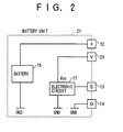
- FIG. 2 is a system block diagram showing an important part of a first embodiment of a battery unit according to the present invention.
- FIG. 2 This embodiment of the battery unit is described as an embodiment of the present invention (refer to FIGS. 2 through 5).
- the present invention is not limited to specific names such as a battery unit and a battery pack. Any battery-including arrangement is included in the present invention.
- FIG. 2 those parts which are the same as those corresponding parts in FIG. 1 are designated by the same reference numerals, and a description thereof will be omitted.
- No power supply circuit 16 is provided within a battery unit 21 shown in FIG. 2.
- a power supply voltage to the electronic circuit 17 is supplied from the outside via terminals 23 and 14.
- the electronic circuit 17 is electrically insulated from the battery 15. For this reason, in a state where the battery unit 21 is stored by itself, no discharge of the battery 15 caused by the electronic circuit 17 occurs.
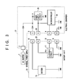
- FIG. 3 is a system block diagram showing a first embodiment of an electronic equipment according to the present invention, together with the battery unit 21 described above.
- those parts which are the same as those corresponding parts in FIG. 1 are designated by the same reference numerals, and a description thereof will be omitted.
- a power supply circuit 35 is provided within an electronic equipment 31 shown in FIG. 3.
- This power supply circuit 31 supplies the power supply voltage from the battery 15 to various parts of the electronic equipment 31, including a microcontroller (or a microcomputer) 36, when the battery unit 21 is connected to the electronic equipment 31 and a present remaining capacity of the battery 15 is greater than or equal to a predetermined value.
- the power supply circuit 35 supplies a power supply voltage from the external power supply to the various parts of the electronic equipment 31, including the microcontroller 36.
- the power supply voltage from the power supply circuit 35 is supplied to the electronic circuit 17 within the battery unit 21 via terminals 33 and 23 and the terminals 5 and 14.
- the electronic circuit 17 includes a non-volatile memory element.
- this non-volatile memory element stores one information selected from a group which includes information related to at least one of regular voltage, current temperature, capacity and serial number of the battery 15, and information related to the present remaining capacity of the battery 15.
- the information which does not change is basically written in advance when the battery unit 21 is manufactured.
- the information which changes such as the information related to the remaining capacity, is initially written when the battery unit 21 is manufactured, and is thereafter written by the microcontroller 36 via the terminals 13 and 4.
- the microcontroller 36 obtains the remaining capacity by accumulating the flowing current via the terminals 12 and 3 and subtracting the accumulated value from a fully charged capacity.
- the remaining capacity obtained is written into the non-volatile memory element of the electronic circuit 17 via the terminals 13 and 4.
- a method of measuring the flowing current it is possible, for example, to use a resistor 51 and a measuring circuit 53 shown in FIG. 5 which will be described later.
- a resistor (corresponding to the resistor 51 shown in FIG. 5) may be connected between a diode which is provided between the electronic equipment 31 and the terminal 3 and a diode which is provided between the terminal 3 and the power supply circuit 35, and a terminal voltage across this resistor may be measured by the microcontroller 36 to obtain the current value of the flowing current.
- the microcontroller 36 of the electronic equipment 31 can use the power supply voltage supplied from the power supply circuit 35 within the electronic equipment 31 and read information from and/or write information to the electronic circuit 17 within the battery unit 21 via the terminals 13 and 4. For this reason, if information indicating that the charging should be prohibited due to a battery abnormality is written in the non-volatile memory element within the electronic circuit 17, for example, the microcontroller 36 can prohibit the charging operation with respect to the battery unit 21.
- the battery abnormality can be judged by the microcontroller 36 when the voltage of the battery 15 does not increase or the fully charged capacity becomes small.
- the microcontroller 36 writes the information which indicates that the charging should be prohibited into the non-volatile memory element of the electronic circuit 17, via the terminals 13 and 4.
- the voltage of the battery 15 can be detected, by measuring a voltage at the terminal 3 by the microcontroller 36. If this voltage does not increase, the microcontroller 36 judges the battery abnormality, and writes the information which indicates that the charging should be prohibited into the non-volatile memory element of the electronic circuit 17, via the terminals 13 and 4.
- the fully charged capacity can be obtained in the following manner.
- the initial value of the fully charged capacity is written advance into the non-volatile memory element of the electronic circuit 17 when the battery unit 21 is manufactured.
- the current flowing from the terminal 3 to the electronic equipment 31 (that is, the above described flowing current which is measured) is accumulated from a state where the battery 15 is fully charged to a state where the remaining capacity is approximately zero, so as to obtain the fully charged capacity of the battery 15.
- the fully charged capacity which is obtained in this manner is updated as a new fully charged capacity.
- the updated fully charged capacity is written into the non-volatile memory element of the electronic circuit 17 via the terminals 4 and 13.
- the microcontroller 36 judges the battery abnormality, and stores the information which indicates that the charging should be prohibited into the non-volatile memory element of the electronic circuit 17, via the terminals 13 and 4.
- the charging operation with respect to the battery unit 21 can be carried out in parallel with the reading of the information from and/or the writing of the information to the electronic circuit 17 within the battery unit 21 by the microcontroller 36.
- the battery unit itself which is provided with an electronic circuit having a memory or the like is known, and for this reason, description and illustration of the specific construction within the electronic circuit 17 will be omitted.
- a microcontroller (or microcomputer) itself within an electronic equipment which reads information from and/or writes information to the memory within the electronic circuit is also known, and thus, a detailed description related to the operation of reading information from and/or writing information with respect to the electronic circuit 17 within the battery unit 21 by the microcontroller 36 will be omitted.
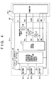
- FIG. 4 is a system block diagram showing this second embodiment of the battery unit.
- those parts which are the same as those corresponding parts in FIG. 2 are designated by the same reference numerals, and a description thereof will be omitted.
- a battery unit 21-1 includes lithium-ion batteries 15-1 through 15-3, switching elements 41 and 42 made up of FETs, for example, a fuse 43, an excessive discharge and/or excessive charging protection control circuit 44, a serial EEPROM 17-1, a thermistor 45, and a terminal group 48 which are connected as shown in FIG. 4.
- the lithium-ion batteries 15-1 through 15-3 form the battery 15.
- Resistors 46 and 47 are provided as pull-up resistors.
- the excessive discharge and/or excessive charging protection control circuit 44 is a known circuit which is provided to protect an excessive discharge and/or an excessive charging of the battery 15.
- the excessive discharge and/or excessive charging protection control circuit 44 prevents the excessive discharge and/or excessive charging by controlling ON/OFF states of the switching elements 41 and 42 depending on the state of the battery 15.
- the fuse 43 is also a known element which cuts a current path when an excessively large current flows through the fuse 43, so as to protect the battery 15.
- an excessive discharge and/or excessive charging protection control circuit described in a Japanese Laid-Open Patent Application No.10-23674 entitled "Battery Remaining Capacity Predicting Method, Battery Unit and Apparatus Using Battery Unit” laid open on January 23, 1998 may be used for the excessive discharge and/or excessive charging protection control circuit 44 described above.
- the Japanese Laid-Open Patent Application No.10-23674 describes the construction and operation related to the excessive discharge and/or excessive charging protection control circuit 44 and the switching elements 41 and 42, but a brief description will be given hereunder.
- the excessive discharge and/or excessive charging protection control circuit 44 is provided within the battery unit 21-1. In this circuit 44, a voltage comparator is provided with respect to each of the batteries 15-1 through 15-3.
- the 3 batteries 15-1 through 15-3 are connected in series, and each voltage comparator is supplied with an output voltage of a corresponding one of the batteries 15-1 through 15-3 and a reference voltage el which indicates an excessive discharge limit voltage of the batteries 15-1 through 15-3.
- the switching element 42 is made of the FET.
- Each voltage comparator outputs a high-level signal when the voltage from the corresponding one of the batteries 15-1 through 15-3 becomes less than or equal to the reference voltage el. Accordingly, when one of the voltage comparators outputs a high-level signal, the switching element 42 is turned OFF in response to the high-level signal, and battery unit 21 is disconnected from an electronic equipment 31-1.
- the battery unit 21-1 is further provided with the switching element 41.
- the excessive discharge and/or excessive charging protection control circuit 44 is further provided with second voltage comparators corresponding to the batteries 15-1 through 15-3.
- the electronic equipment 31-1 is further provided with a charger (not shown). An excessive charging prevention circuit is formed by a part of the excessive discharge and/or excessive charging protection control circuit 44 and the switching element 41.
- Each of the second voltage comparators is supplied with the output voltage of the corresponding one of the batteries 15-1 through 15-3 and a reference voltage e2 which indicates an excessive charging limit voltage.
- Each second voltage comparator outputs a high-level signal when the voltage from the corresponding one of the batteries 15-1 through 15-3 becomes greater than or equal to the reference voltage e2 which is different from the reference voltage el described above.
- the switching element 41 is turned OF in response to this high-level signal, and the battery unit 21-1 is disconnected from the electronic equipment 31-1.
- the battery unit 21-1 is cut off from the charger of the electronic equipment 31-1, so as to prevent the excessive charging of the batteries 15-1 through 15-3.
- the serial EEPROM 17-1 stores one information selected from a group which includes information related to at least one of regular voltage, current temperature, capacity and serial number of the battery 15, and information related to the present remaining capacity of the battery 15. The remaining capacity may be obtained similarly to the case described above in conjunction with FIG. 3.
- the serial EEPROM 17-1 is connected to the thermistor 45 via the terminal group 48, but is electrically insulated from the battery 15, so that no power supply voltage from the battery 15 is supplied to the serial EEPROM 17-1.
- the serial EEPROM 17-1 includes a power supply voltage input terminal Vcc, a clock input terminal CLK, a data input terminal DAT, and a ground terminal GND.
- the terminal group 48 includes a terminal (+) corresponding to the terminal 12, terminals T+ and Vdd corresponding to the terminal 23, terminals CLOCK and DATA corresponding to the terminal 13, and terminals GND and (-) corresponding to the terminal 14.
- the serial EEPROM 17-1 and the thermistor 45 form the electronic circuit.
- the terminal group 48 is connected to a connector 38 of the electronic equipment 31-1.
- the thermistor 45 is used to measure a temperature within the battery unit 21-1. It is possible to measure the temperature within the battery unit 21-1 by measuring the voltage at the terminal T+ in the electronic equipment 31-1.
- the electronic equipment 31-1 includes the microcontroller 36 identical to that of the electronic equipment 31 described above and shown in FIG. 3.
- the terminals as described above, the terminals CLOCK and DATA shown in FIG. 4 correspond to the terminal 13 shown in FIG. 3.
- the terminal Vdd shown in FIG. 4 corresponds to the terminal 23 shown in FIG. 3.
- the methods of storing the information related to the remaining capacity and the battery abnormality into the serial EEPROM 17-1 may be the same as those described above in conjunction with FIG. 3.
- the construction of the electronic equipment 31-1 in stages subsequent to the connector 36 is the same as that of the electronic equipment 31 shown in FIG. 3, for example.
- FIG. 5 is a system block diagram showing this third embodiment of the battery unit.
- those parts which are the same as those corresponding parts in FIG. 2 are designated by the same reference numerals, and a description thereof will be omitted.
- a battery unit 21-2 includes the battery 15, an electronic circuit 17-2 including a microcontroller (or microcomputer), a resistor 51, a switching circuit 52, a measuring circuit 53, a non-volatile memory device 54, a timer 55, and terminals 12 through 14 and 23 which are connected as shown in FIG. 5. At least one of the switching circuit 52, the measuring circuit 53 and the non-volatile memory device 54 may be provided within the electronic circuit 17-2.
- the supply of the power supply voltage to the electronic circuit 17-2, the resistor 51, the switching circuit 52, the measuring circuit 53 and the non-volatile memory device 54 is made from the power supply circuit 35 within the electronic equipment 31, but otherwise, the basic construction of the battery unit 21-2 is the same as the so-called smart battery.
- the non-volatile memory device 54 stores a current value detected upon completion of the charging, a fully charged capacity (rated capacity), a time set for an excessive charging preventing timer, a tolerable temperature range for the charging, a table of open voltages and remaining capacities, battery information, various parameters used for predicting the remaining capacity, and the like.
- the charging current decreases as the charging progresses, and it is judged that battery 15 is fully charged when the charging current becomes less than or equal to a regular current value.
- the above described current value detected upon completion of the charging refers to this regular current value.
- the fully charged capacity described above is used when calculating the remaining capacity of the battery 15.
- the above described time set for the excessive charging preventing timer is used as a setting time of a charging timer for preventing an excessive charging when the completion of the charging cannot be detected for some reason.
- the tolerable temperature range for the charging is set so as to prevent the charging outside the predetermined temperature range.
- the battery 15 is made up of the lithium-ion battery, it is possible to predict to a certain extent the remaining capacity of the battery 15 based on the battery voltage in an open state where no current flows.
- the table of open voltages and remaining capacities described above is used to predict the remaining capacity of the battery 15 from the open voltage.
- the battery information described above includes product information (name of model), serial number, date (day, month and year) of manufacture and the like related to the battery unit 21-2.
- the switching circuit 52 is turned ON when supplied with an external power supply voltage, that is, the power supply voltage from the electronic equipment 31 via the terminal 23.
- the switching circuit 52 enables the measuring circuit 53 connected thereto to measure the voltage, current and the like of the battery 15.
- the measuring circuit 53 can detect the voltage across the terminals of the resistor 51 so as to detect the current value.
- the measuring circuit 53 can measure the voltage at a node which connects the resistor 51 and the switching circuit 52 at the upper left hand side in FIG. 5, so as to detect the voltage of the battery 15.
- the power supply voltage from the batter 15 is supplied directly to the timer 55. This timer 55 measures a time for which the battery unit 21-2 is disconnected from the electronic equipment 31, and supplies the measured time to the microcontroller within the electronic circuit 17-2.
- the microcontroller within the electronic circuit 17-2 operates based on the power supply voltage which is supplied from the power supply circuit 35 within the electronic equipment 31 via the terminal 23.
- This microcontroller within the electronic circuit 17-2 measures the voltage of the battery 15, the discharge current from the battery 15, the charging current to the battery 15 and the like via the measuring circuit 53, and predicts the remaining capacity of the battery 15.
- the predicted remaining capacity of the battery 15 is supplied to the microcontroller 36 within the electronic equipment 31 via the terminal 13, and is stored in the non-volatile memory device 54 if necessary.
- the method of calculating the remaining capacity of the battery 15 may be the same as that used in the embodiment shown in FIG. 3.
- the calculation (or prediction) of the remaining capacity is made by the microcontroller 36.
- the current value is measured by the resistor 51 and the measuring circuit 53, and the electronic circuit 17-2 uses the measured current value to calculate (or predict) the remaining capacity of the battery 15.
- the microcontroller within the electronic circuit 17-2 detects the time for which the battery unit 21-2 was disconnected from the electronic equipment 31 from the information from the timer 55, and calculates the discharge quantity of the battery 15 during this time when the battery unit 21-2 was disconnected from the electronic equipment 31. By subtracting this discharge quantity from the remaining capacity stored in the non-volatile memory device 54, the microcontroller within the electronic circuit 17-2 can predict the present remaining capacity of the battery 15.
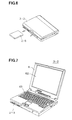
- FIG. 6 is a perspective view showing a second embodiment of the electronic equipment according to the present invention.
- the present invention is applied to a portable personal computer.
- FIG. 6 an important part of a portable personal computer 31-2 has a construction similar to that of the electronic equipment 31 shown in FIG. 3, for example. A known construction may be used for the other parts of the portable personal computer 31-2.
- a battery unit 21-3 has a construction similar to any one of the battery unit 21 shown in FIG. 2, the battery unit 21-1 shown in FIG. 4, and the battery unit 21-2 shown in FIG. 5.
- FIG. 7 is a perspective view showing a state where a lid 61 of the portable personal computer 31-2 shown in FIG. 6 is open.
- the portable personal computer 31-2 includes a display 62 which is provided on the inner side of the lid 61, a keyboard 63, and the like.
- the battery unit 21-3 is inserted from a front part of the portable personal computer 31-2.
- the portable personal computer forms the electronic equipment.
- the application of the present invention is of course not limited to the portable personal computer.
- the present invention is similarly applicable to various other electronic equipments which use a battery, such as Personal Digital Assistance (PDA) equipments, electronic memo devices, and video cameras.
- PDA Personal Digital Assistance
- the present invention it is possible to effectively suppress a discharge of a battery when the battery unit is stored by itself so as to prevent deterioration of the battery, and to immediately read information stored within the battery unit regardless of a state of the battery within the battery unit.
Landscapes
- Engineering & Computer Science (AREA)
- Power Engineering (AREA)
- Charge And Discharge Circuits For Batteries Or The Like (AREA)
- Secondary Cells (AREA)
- Power Sources (AREA)
- Lock And Its Accessories (AREA)
- Battery Mounting, Suspending (AREA)
- Stand-By Power Supply Arrangements (AREA)
Applications Claiming Priority (2)
| Application Number | Priority Date | Filing Date | Title |
|---|---|---|---|
| JP1761099 | 1999-01-26 | ||
| JP11017610A JP2000215919A (ja) | 1999-01-26 | 1999-01-26 | 電子機器及び電池ユニット |
Publications (2)
| Publication Number | Publication Date |
|---|---|
| EP1024576A2 true EP1024576A2 (fr) | 2000-08-02 |
| EP1024576A3 EP1024576A3 (fr) | 2004-11-10 |
Family
ID=11948667
Family Applications (1)
| Application Number | Title | Priority Date | Filing Date |
|---|---|---|---|
| EP99308544A Withdrawn EP1024576A3 (fr) | 1999-01-26 | 1999-10-28 | Equipement électronique et unité de batterie |
Country Status (4)
| Country | Link |
|---|---|
| US (1) | US6498459B1 (fr) |
| EP (1) | EP1024576A3 (fr) |
| JP (2) | JP2000215919A (fr) |
| CN (3) | CN100533910C (fr) |
Families Citing this family (23)
| Publication number | Priority date | Publication date | Assignee | Title |
|---|---|---|---|---|
| US6832324B2 (en) * | 2000-05-16 | 2004-12-14 | Richmount Computers Limited | Method for providing a device communicating to a backplane the current status of an associated power supply unit connected to the backplane |
| IES20010399A2 (en) * | 2000-05-16 | 2002-02-06 | Richmount Computers Ltd | A protocol for a power supply unit controller |
| IES20010398A2 (en) * | 2000-07-06 | 2002-02-06 | Richmount Computers Ltd | Improved power supply unit controller |
| TW501326B (en) * | 2001-01-10 | 2002-09-01 | Tai-He Yang | Electric equipment with backup battery-stand powered by host machine power source |
| JP2002343441A (ja) * | 2001-05-16 | 2002-11-29 | Sony Corp | 二次電池の保護回路およびその調整方法 |
| JP4794760B2 (ja) * | 2001-07-04 | 2011-10-19 | パナソニック株式会社 | 電池パック |
| US6924625B2 (en) * | 2003-03-24 | 2005-08-02 | Sanyo Electric Co., Ltd. | Battery pack and method of detecting battery pack abnormalities |
| US8040430B2 (en) * | 2003-07-18 | 2011-10-18 | Nikon Corporation | Battery capacity display device and camera |
| KR100938075B1 (ko) * | 2004-08-30 | 2010-01-21 | 삼성에스디아이 주식회사 | 스마트 배터리 및 이를 이용한 배터리 유형 판별 방법 |
| JP2007195021A (ja) * | 2006-01-20 | 2007-08-02 | Nec Electronics Corp | 携帯端末装置 |
| JP5048963B2 (ja) * | 2006-04-06 | 2012-10-17 | パナソニック株式会社 | 電池システム |
| US20070250725A1 (en) * | 2006-04-20 | 2007-10-25 | Pang-Chiang Chia | Power Saving Device for an Actuator |
| JP4821691B2 (ja) * | 2007-04-19 | 2011-11-24 | Necエナジーデバイス株式会社 | 二次電池パック |
| JP5243086B2 (ja) * | 2008-04-04 | 2013-07-24 | 株式会社マキタ | 充電装置、及びプログラム |
| JP2013009574A (ja) * | 2011-06-22 | 2013-01-10 | Csr Inc | 充電式電気・電子装置 |
| JP5978596B2 (ja) * | 2011-11-07 | 2016-08-24 | ソニー株式会社 | 制御装置および制御方法 |
| US20150029398A1 (en) * | 2013-07-24 | 2015-01-29 | Kabushiki Kaisha Toshiba | Information processing apparatus and information processing method for outputting a charging status |
| TWI547057B (zh) * | 2014-03-21 | 2016-08-21 | 台灣立凱綠能移動股份有限公司 | 電池管理裝置 |
| JP2015208139A (ja) * | 2014-04-22 | 2015-11-19 | 株式会社豊田自動織機 | 電源装置 |
| US9413177B2 (en) * | 2014-11-05 | 2016-08-09 | Motorola Solutions, Inc. | Efficient apparatus and method for inhibiting corrosion with discharge blocking features in a battery |
| WO2017022169A1 (fr) * | 2015-07-31 | 2017-02-09 | パナソニックIpマネジメント株式会社 | Dispositif de commande de batterie, appareil électronique, bloc de batterie, et procédé de commande de batterie |
| CN110068765B (zh) * | 2018-01-19 | 2021-06-15 | 新盛力科技股份有限公司 | 电池容量的预估方法 |
| JP7668829B2 (ja) | 2023-01-31 | 2025-04-25 | 本田技研工業株式会社 | 給電制御システムおよび利用対象機器 |
Family Cites Families (18)
| Publication number | Priority date | Publication date | Assignee | Title |
|---|---|---|---|---|
| JPH0530926A (ja) | 1991-07-29 | 1993-02-09 | Ryoju Shoji Kk | 発酵花粉栄養調整物 |
| JPH05333974A (ja) | 1992-05-28 | 1993-12-17 | Sanyo Electric Co Ltd | バッテリ管理システム |
| CN1119054A (zh) * | 1993-03-05 | 1996-03-20 | 摩托罗拉公司 | 具有存储器的存储充电过程的电池 |
| FR2704982B1 (fr) * | 1993-05-06 | 1995-06-09 | Alsthom Cge Alcatel | Systeme de reconnaissance et de gestion de generateurs electrochimiques. |
| JP3272108B2 (ja) * | 1993-07-07 | 2002-04-08 | 三洋電機株式会社 | パック電池 |
| JPH07230344A (ja) * | 1994-02-21 | 1995-08-29 | Toshiba Corp | 携帯型電子機器及び電池パック |
| US5606242A (en) | 1994-10-04 | 1997-02-25 | Duracell, Inc. | Smart battery algorithm for reporting battery parameters to an external device |
| US5568039A (en) * | 1994-12-16 | 1996-10-22 | Motorola, Inc. | Apparatus and method of providing an initiation voltage to a rechargeable battery system |
| JP3649296B2 (ja) | 1995-05-12 | 2005-05-18 | ソニー株式会社 | バッテリパックおよび電子機器 |
| US5625291A (en) * | 1995-05-16 | 1997-04-29 | Brink; Gregory D. | System for exchanging information in a battery mailbox |
| US5641587A (en) * | 1995-12-15 | 1997-06-24 | Compaq Computer Corporation | Battery pack with a monitoring circuit for a known system |
| US6522361B2 (en) * | 1996-03-08 | 2003-02-18 | Sony Corporation | Electronic apparatus having the function of displaying the battery residual quantity and method for displaying the battery residual quantity |
| JP3618472B2 (ja) | 1996-07-01 | 2005-02-09 | 富士通株式会社 | 電池ユニット及び電池ユニットを使用する装置 |
| KR980012672A (ko) * | 1996-07-16 | 1998-04-30 | 손욱 | 지능형 배터리 장치 |
| US5854549A (en) * | 1996-09-24 | 1998-12-29 | Motorola, Inc. | Contact arrangement having an auxiliary contact |
| JP3437397B2 (ja) | 1996-12-27 | 2003-08-18 | キヤノン株式会社 | 情報処理装置、電池パックおよび電池パックの電池残量算出方法 |
| JP3735999B2 (ja) * | 1997-02-20 | 2006-01-18 | ソニー株式会社 | 充電装置 |
| US6133708A (en) * | 1998-06-16 | 2000-10-17 | U.S. Philips Corporation | Radio apparatus comprising a charging device |
-
1999
- 1999-01-26 JP JP11017610A patent/JP2000215919A/ja active Pending
- 1999-10-28 EP EP99308544A patent/EP1024576A3/fr not_active Withdrawn
- 1999-11-09 US US09/437,288 patent/US6498459B1/en not_active Expired - Fee Related
- 1999-11-18 CN CNB2004100054493A patent/CN100533910C/zh not_active Expired - Fee Related
- 1999-11-18 CN CNA2008101760656A patent/CN101447685A/zh active Pending
- 1999-11-18 CN CN99124442A patent/CN1262544A/zh active Pending
-
2008
- 2008-11-10 JP JP2008287641A patent/JP2009106150A/ja active Pending
Also Published As
| Publication number | Publication date |
|---|---|
| JP2009106150A (ja) | 2009-05-14 |
| US6498459B1 (en) | 2002-12-24 |
| CN100533910C (zh) | 2009-08-26 |
| EP1024576A3 (fr) | 2004-11-10 |
| CN101447685A (zh) | 2009-06-03 |
| CN1262544A (zh) | 2000-08-09 |
| CN1525617A (zh) | 2004-09-01 |
| JP2000215919A (ja) | 2000-08-04 |
Similar Documents
| Publication | Publication Date | Title |
|---|---|---|
| US6498459B1 (en) | Electronic equipment and battery unit | |
| US5903131A (en) | Battery set structure and charge/discharge control apparatus for lithium-ion battery | |
| US6060864A (en) | Battery set structure and charge/discharge control apparatus for lithium-ion battery | |
| US6897635B2 (en) | Method for predicting remaining charge of portable electronics battery | |
| US5432429A (en) | System for charging/monitoring batteries for a microprocessor based system | |
| US9172261B2 (en) | Battery pack, method of charging secondary battery and battery charger | |
| JP3908463B2 (ja) | 電池保護回路及び保護方法 | |
| KR100686794B1 (ko) | 배터리팩의 모니터링 장치 및 그 방법 | |
| US8148946B2 (en) | Battery pack having protection circuit for secondary battery | |
| US10298031B2 (en) | Battery device and battery protection method | |
| US6501249B1 (en) | Battery management system | |
| US8125190B2 (en) | Battery charging system | |
| US6456948B1 (en) | Method of generating data for use in monitoring and controlling charge and discharge status of secondary battery | |
| US6160377A (en) | Battery charging device and method and electronic device | |
| CN101005145A (zh) | 电池组以及使电池组的功能永久停止的方法 | |
| US10084326B2 (en) | Highly accurate over current fault protection for battery packs | |
| JP3859608B2 (ja) | 電池パック、電子機器、電池残量予測システム及び半導体装置 | |
| US6522104B1 (en) | Method and apparatus for measurement of charge in a battery | |
| US7039150B1 (en) | Serial interface for a battery management system | |
| KR100818519B1 (ko) | 배터리 관리 방법 및 장치 | |
| CN112020809B (zh) | 电池保护电路和使用该电池保护电路的过电流阻断方法 | |
| JP3194439B2 (ja) | 電池パック | |
| EP2312723A2 (fr) | Bloc-batteries et procédé pour contrôler le fonctionnement de flash de données | |
| KR100512165B1 (ko) | 충전 가능한 배터리의 용량 측정 방법 | |
| JP2004279145A (ja) | 2次電池容量計測のための半導体装置 |
Legal Events
| Date | Code | Title | Description |
|---|---|---|---|
| PUAI | Public reference made under article 153(3) epc to a published international application that has entered the european phase |
Free format text: ORIGINAL CODE: 0009012 |
|
| AK | Designated contracting states |
Kind code of ref document: A2 Designated state(s): AT BE CH CY DE DK ES FI FR GB GR IE IT LI LU MC NL PT SE |
|
| AX | Request for extension of the european patent |
Free format text: AL;LT;LV;MK;RO;SI |
|
| PUAL | Search report despatched |
Free format text: ORIGINAL CODE: 0009013 |
|
| AK | Designated contracting states |
Kind code of ref document: A3 Designated state(s): AT BE CH CY DE DK ES FI FR GB GR IE IT LI LU MC NL PT SE |
|
| AX | Request for extension of the european patent |
Extension state: AL LT LV MK RO SI |
|
| 17P | Request for examination filed |
Effective date: 20050105 |
|
| AKX | Designation fees paid |
Designated state(s): DE FR GB |
|
| 17Q | First examination report despatched |
Effective date: 20070823 |
|
| 18D | Application deemed to be withdrawn |
Effective date: 20110501 |
|
| STAA | Information on the status of an ep patent application or granted ep patent |
Free format text: STATUS: THE APPLICATION IS DEEMED TO BE WITHDRAWN |
|
| R18D | Application deemed to be withdrawn (corrected) |
Effective date: 20110502 |