EP1025633B1 - Rotor mit permanentmagneten für einien elektromotor - Google Patents
Rotor mit permanentmagneten für einien elektromotor Download PDFInfo
- Publication number
- EP1025633B1 EP1025633B1 EP98952456A EP98952456A EP1025633B1 EP 1025633 B1 EP1025633 B1 EP 1025633B1 EP 98952456 A EP98952456 A EP 98952456A EP 98952456 A EP98952456 A EP 98952456A EP 1025633 B1 EP1025633 B1 EP 1025633B1
- Authority
- EP
- European Patent Office
- Prior art keywords
- magnets
- annular
- electric motor
- motor rotor
- circumferential displacement
- Prior art date
- Legal status (The legal status is an assumption and is not a legal conclusion. Google has not performed a legal analysis and makes no representation as to the accuracy of the status listed.)
- Expired - Lifetime
Links
Images
Classifications
-
- H—ELECTRICITY
- H02—GENERATION; CONVERSION OR DISTRIBUTION OF ELECTRIC POWER
- H02K—DYNAMO-ELECTRIC MACHINES
- H02K1/00—Details of the magnetic circuit
- H02K1/06—Details of the magnetic circuit characterised by the shape, form or construction
- H02K1/22—Rotating parts of the magnetic circuit
- H02K1/27—Rotor cores with permanent magnets
- H02K1/2706—Inner rotors
- H02K1/272—Inner rotors the magnetisation axis of the magnets being perpendicular to the rotor axis
- H02K1/274—Inner rotors the magnetisation axis of the magnets being perpendicular to the rotor axis the rotor consisting of two or more circumferentially positioned magnets
- H02K1/2753—Inner rotors the magnetisation axis of the magnets being perpendicular to the rotor axis the rotor consisting of two or more circumferentially positioned magnets the rotor consisting of magnets or groups of magnets arranged with alternating polarity
- H02K1/278—Surface mounted magnets; Inset magnets
Definitions
- the present invention refers to an electric motor rotor with permanent magnets, said rotor including a core having a cylindrical lateral surface, against which are seated magnets having opposite lateral edges, and a pair of annular caps comprising positioning means, limiting axial displacements of the magnets and defining, for both directions of circumferential displacement, stops for this displacement for each magnet, the confronting lateral edges of a pair of consecutive magnets being positioned by said annular caps, in order to define a previously established minimum circumferential distance.
- the permanent magnets In the known constructions for a brushless electric motor rotor, the permanent magnets, usually in the form of arcuated plates, are retained on a cylindrical core, usually made of iron (US5302876), which may be laminated or massive and which is mounted around the motor shaft.
- the magnets are provided in housings defined by longitudinal openings inside the metallic core or kept seated on the cylindrical lateral surface of the core through different fixation means, which are designed to impart to the mechanical structure the necessary resistance to centrifugal forces and to the motor operation.
- the positioning of the magnets on the rotor surface by means of external radial saliences of the core causes an assembly difficulty, which resides on the fact that the magnets are supported on only one of said saliences, since, during the operation of the motor or also during the mounting process of said rotor, the different thermal expansion of both the magnets and the core may generate high mechanical stresses concentrated on the magnets at the supporting region, in case the magnets are simultaneously supported on two opposite saliences. These stresses may cause failures caused by magnet breakage, as they are formed of ceramic material. In certain cases, even the support on only one salience can be critical.
- the rotor After the formation of the rotor, with the magnets correctly positioned around the core, the rotor has to be positioned and mounted around the motor shaft, when positioning means are required to align the rotor during its assembly phase around the motor shaft. These positioning means also position the rotor for the posterior magnetization of the magnets, which has to be effected in a predetermined position of said magnets in relation to the motor structure.
- This positioning function is usually provided by bores, which are made in the magnetic core of the rotor and which reduce the amount of active material of said core, impairing the efficiency of the motors or limiting the minimum size that the rotors may have, without the bores impairing relevantly the performance of said motor.
- an electric motor rotor with permanent magnets said rotor including a core having a cylindrical lateral surface, against which are seated magnets having opposite lateral edges, and a pair of annular caps comprising positioning means, limiting axial displacements of the magnets defining, for both directions of circumferential displacement, stops for displacement for each magnet, the confronting lateral edges of a pair of consecutive magnets being positioned by said annular caps, in order to define a previously established minimum circumferential distance
- the electric motor rotor being characterized in that each cap is seated and fixed to an adjacent end face of the core and each positioning means limiting the circumferential displacement of a respective magnet in one direction of circumferential displacement, each magnet having its circumferential displacement, in both directions, limited by two circumferential displacement limiting stops, each one provided in one of the annular caps, said circumferential displacement limiting stops which act on the same magnet being seated against diagonally opposite end portions of lateral edges of said magnet.
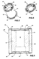
- the present invention refers to an electric motor rotor of the type with permanent magnets and having a core 10 to be affixed around an extension of the motor shaft S and in whose cylindrical lateral surface 11 are seated magnets 20, usually in the form of arcuated magnetic plates, said magnets 20 being retained against the core 10, for example by gluing or by actuation of a tubular cylindrical cap 30, so that each of their respective lateral edges 21 be spaced from a confronting lateral edge 21 of an adjacent magnet by a previously determined minimum distance.
- At least one of the annular caps 40 comprises circumferential displacement limiting stops 42 which limit both directions of circumferential displacement of a respective magnet 20.
- the circumferential displacement limiting stops 42 are provided according to a same cicumferential alignment internal to the circumferential alignment of the external face of the magnets 20.
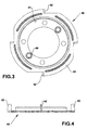
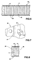
- each annular cap 40 incorporates, in a single piece, a peripheral annular flange 43, defined, for example on a plane which is parallel in relation to the plane of the annular cap 40, said peripheral annular flange 43 carrying the circumferential displacement limiting stops 42, for example in the form of axial ears incorporated to the annular cap 40 and projecting from the plane of the peripheral annular flange 43 of the latter and which are angularly spaced from each other, each defining a circumferential stop, acting against an end portion of a lateral edge 21 of a respective magnet 20, upon mounting the magnets around the rotor core.
- the peripheral annular flange may be further defined parallel or coplanar in relation to the plane of the annular cap 40.
- the circumferential displacement limiting stops 42 should have a determined flexibility, sufficient to allow the deformation thereof, for example resulting from thermal expansion of the magnet for which it actuates as a circumferential displacement limiting means. An eventual deformation of said stops 42 avoids high stresses on the magnets 20 and the consequent damages caused to said magnets.
- the annular caps are attached to the rotor, so that their circumferential displacement limiting stops 42 assure that the confronting lateral edges 21 of a consecutive pair of magnets 20 be positioned at a determined previously established minimum distance between said magnets when mounted around the rotor core.
- circumferential displacement limiting stops 42 are radially and angularly spaced from each other, in order to avoid mutual contact in any deformation condition of said magnets 20.
- the circumferential displacement limiting stops 42 have their length dimensioned, considering the possible dimensional variations (and margins of error) in the length of said magnets.
- the distance between each two adjacent circumferential displacement limiting stops 42 related to a respective magnet is defined taking into account the variations of circumferential extension (and margins of error) of said magnets 20.
- the circumferential displacement limiting stops 42 of the present solution are designed to guarantee, upon assembly of the magnets 20 to the rotor core, a desired relative positioning between said magnets, without however necessarily acting against said magnets 20 during this assembly condition or even after obtaining the retaining condition of said magnets to the rotor core.
- annular caps 40 are attached to the rotor, so that their respective circumferential displacement limiting stops 42, acting on the same lateral edge portion 21 of each magnet 20 be axially aligned to each other.
- each magnet 20 mounted to the core 10 has a pair of circumferential displacement limiting stops 42, each acting against an adjacent end portion of one of the diagonally opposite lateral edges 21.
- the circumferential displacement limiting stops 42 are also equally spaced from each other, as a function of their actuation in relation to the magnets 20.
- the distribution of the circumferential displacement limiting stops 42 throughout the peripheral annular flange 43 of each annular cap 40 may present variable spacings, defined as a function of the actuation or said circumferential displacement limiting stops 42 on each magnet 20.
- the level difference between the plane of the annular cap 40 and its peripheral annular flange 43 allows the use of magnets having an axial length which may be larger or smaller than that of the rotor core.
- the attachment of at least one of the annular caps 40 to the core 10 determines the circumferential positioning for retaining each magnet 20 to said core 10.
- the assembly of the annular cap 40 adjacently to the lower end face of the core 10 further determines an axial retention of said magnets 20 in relation to the core 10. This retention results from each magnet 20 being seated against an inner face of the peripheral annular flange 43 of the annular cap 40 located at the bottom of the core 10.
- the circumferential displacement limiting stops 42 are in the form of axial ears
- the latter may be formed with the same material of the corresponding cap 40 and incorporated in a single piece thereto (by stamping, casting, injection, etc.) and produced by one of the processes of folding, stamping, bending, etc., or may be affixed to the respective cap 40 by an adequate process, such as riveting, welding, gluing or mechanical interference.
- the axial ears 42 attachable to the annular cap 40 may be obtained from a different material than that which forms the annular cap 40.
- the joint actuation of the pair of annular caps 40 in relation to the core 10 determines a circumferential and longitudinal alignment of the magnets 20 seated on the rotor core.
- each annular cap 40 is further provided with positioning means 44 in the form of bores or portions which are upwardly drawn from the surface of the annular cap 40, said positioning means 44 allowing the angular positioning of the rotor upon assembly of the magnets (or, eventually, during the formation or placement of the cap around said magnets), said positioning means 44 avoiding the need for providing bores in the magnetic core of the rotor and circumferentially locking the rotor in relation to the shaft S, during the assembly in any of the mounting positions of the magnets or cap, mainly when the latter is coiled.
- the assembly with the correct circumferential and longitudinal alignments of the magnets 20 in relation to the core 10 is achieved in a simple way, with no need for using sophisticated equipments, or removing material from the core 10, since no bores are made in the latter, making the motor more efficient and/or more compact.
- the circumferential displacement limiting stops 42 further avoid the occurrence of concentrations of mechanical stresses of thermal origin, which usually lead to breakage of the magnetic material.
- the annular cap 40 of the present invention may present the circumferential displacement limiting stops 42 in the form of radial projections, each provided with a respective axial extension orthogonal to the plane of the annular cap, said radial projections acting in the circumferential locking of at least one adjacent magnet 20.
Landscapes
- Engineering & Computer Science (AREA)
- Power Engineering (AREA)
- Permanent Field Magnets Of Synchronous Machinery (AREA)
- Permanent Magnet Type Synchronous Machine (AREA)
- Reciprocating, Oscillating Or Vibrating Motors (AREA)
Claims (12)
- Rotor mit Permanentmagneten für einen Elektromotor, wobei der Rotor einen Kern (10) mit einer zylindrischen Seitenfläche, an der Magnete (20) sitzen, die gegenüberliegende Seitenkanten (21) aufweisen, und ein Paar ringförmiger Kappen (40) mit Positioniermitteln (42) aufweist, die Axialverschiebungen der Magnete begrenzen und in beiden Richtungen einer Verschiebung in Umfangsrichtung für jeden Magneten (20) Anschläge für diese Verschiebung festlegen, wobei die zusammenlaufenden Seitenkanten (21) eines Paars aufeinanderfolgender Magnete (20) durch die ringförmigen Kappen (40) positioniert werden, um einen zuvor bestimmten Mindestabstand in Umfangsrichtung festzulegen, dadurch gekennzeichnet, daß jede Kappe auf einer benachbarten Endfläche (12) des Kems (10) sitzt und an dieser befestigt ist und jedes Positioniermittel (42) die Verschiebung eines zugeordneten Magneten (20) in Umfangsrichtung in einer Richtung einer Verschiebung in Umfangsrichtung begrenzt, wobei die Verschiebung jedes Magneten (20) in Umfangsrichtung in beiden Richtungen durch zwei eine Verschiebung in Umfangsrichtung begrenzende Anschläge (42) begrenzt ist, deren jeder in einer der ringförmigen Kappen (40) vorgesehen ist, und die eine Verschiebung in Umfangsrichtung begrenzenden Anschläge (42), die auf denselben Magneten (20) einwirken, an einander diagonal gegenüberliegenden Endbereichen von Seitenkanten (21) dieses Magneten (20) sitzen.
- Rotor für einen Elektromotor nach Anspruch 1, dadurch gekennzeichnet, daß jeder der eine Verschiebung in Umfangsrichtung begrenzenden Anschläge (42), die in beiden ringförmigen Kappen (40) vorgesehen sind und auf denselben Magneten (20) wirken, jeweils am Endabschnitt einer benachbarten Seitenkante (21) eines Magneten (20) sitzt.
- Rotor für einen Elektromotor nach Anspruch 2, dadurch gekennzeichnet, daß die benachbarten, eine Verschiebung in Umfangsrichtung begrenzenden Anschläge (42) einer ringförmigen Kappe (40), deren jeder die Verschiebung in Umfangsrichtung eines Magneten (20) in einer Verschiebungsrichtung begrenzt, in einem Abstand voneinander angeordnet sind, der dem zwischen den Magneten (20) einzuhaltenden Mindestabstand in Umfangsrichtung entspricht.
- Rotor für einen Elektromotor nach Anspruch 1, dadurch gekennzeichnet, daß jede ringförmige Kappe (40) in einem einzigen Teil einen in Umfangsrichtung verlaufenden Ringflansch (43) aufweist, der die eine Verschiebung in Umfangsrichtung begrenzenden Anschläge (42) trägt.
- Rotor für einen Elektromotor nach Anspruch 4, dadurch gekennzeichnet, daß die eine Verschiebung in Umfangsrichtung begrenzenden Anschläge (42) durch axiale Ansätze festgelegt sind, die am peripheren Ringflansch (43) befestigt sind.
- Rotor für einen Elektromotor nach Anspruch 5, dadurch gekennzeichnet, daß jeder axiale Ansatz einstückig an der zugeordneten ringförmigen Kappe (40) ausgebildet ist.
- Rotor für einen Elektromotor nach Anspruch 6, dadurch gekennzeichnet, daß jeder axiale Ansatz durch eines der folgenden Verfahren hergestellt ist: durch Stanzen, Falten und Biegen einer Verlängerung des peripheren Ringflansches (43) der zugeordneten ringförmigen Kappe (40).
- Rotor für einen Elektromotor nach Anspruch 7, dadurch gekennzeichnet, daß die axialen Ansätze durch eines der folgenden Verfahren angebracht sind: Nieten, Schweißen, Kleben und mechanisches Verhaken.
- Rotor für einen Elektromotor nach Anspruch 1, dadurch gekennzeichnet, daß jede ringförmige Kappe (40) durch eines der folgenden Verfahren erhalten wird: Stanzen, Spritzgießen und Gießen.
- Rotor für einen Elektromotor nach Anspruch 1, dadurch gekennzeichnet, daß die ringförmigen Kappen (40) und die eine Verschiebung in Umfangsrichtung begrenzenden Anschläge (42) aus einem Material mit einer Durchlässigkeit, die deutlich geringer als die des Kerns (10) ist, ausgebildet sind.
- Rotor für einen Elektromotor nach Anspruch 1, dadurch gekennzeichnet, daß er von einer Außenfläche jeder ringförmigen Kappe (40) aus Positioniermittel (44) mit mindestens einer der folgenden Funktionen aufweist: Winkelpositionieren des Rotors relativ zur Motorwelle während der Montage der Magnete (20), Ausbilden einer Kappe um die Magnete (20) herum und Arretieren des Rotors in Umfangsrichtung relativ zur Motorwelle (S) in einem beliebigen der Montagezustände der Magnete (20) und der Kappen.
- Rotor für einen Elektromotor nach Anspruch 1, dadurch gekennzeichnet, daß jede ringförmige Kappe (40), die den zugeordneten Ringflansch (43) und die axialen Ansätze (42) aufweist, durch eines der folgenden Verfahren erhalten wird: durch Stanzen, Spritzgießen und Gießen, wobei der Ringflansch (43) und die axialen Ansätze (42) beim Stanzvorgang durch eines der Verfahren Falten und Biegen der ringförmigen Kappe (40) erhalten werden.
Applications Claiming Priority (3)
| Application Number | Priority Date | Filing Date | Title |
|---|---|---|---|
| BRPI9705306-6A BR9705306B1 (pt) | 1997-10-24 | 1997-10-24 | rotor de motor elétrico. |
| BR9705306 | 1997-10-24 | ||
| PCT/BR1998/000085 WO1999022435A1 (en) | 1997-10-24 | 1998-10-22 | An electric motor rotor with permanent magnets |
Publications (2)
| Publication Number | Publication Date |
|---|---|
| EP1025633A1 EP1025633A1 (de) | 2000-08-09 |
| EP1025633B1 true EP1025633B1 (de) | 2003-03-26 |
Family
ID=4068182
Family Applications (1)
| Application Number | Title | Priority Date | Filing Date |
|---|---|---|---|
| EP98952456A Expired - Lifetime EP1025633B1 (de) | 1997-10-24 | 1998-10-22 | Rotor mit permanentmagneten für einien elektromotor |
Country Status (9)
| Country | Link |
|---|---|
| US (1) | US6339274B1 (de) |
| EP (1) | EP1025633B1 (de) |
| JP (1) | JP4316795B2 (de) |
| CN (1) | CN1187875C (de) |
| AT (1) | ATE235756T1 (de) |
| BR (1) | BR9705306B1 (de) |
| DE (1) | DE69812678T2 (de) |
| ES (1) | ES2198076T3 (de) |
| WO (1) | WO1999022435A1 (de) |
Families Citing this family (13)
| Publication number | Priority date | Publication date | Assignee | Title |
|---|---|---|---|---|
| TW513841B (en) * | 2000-04-04 | 2002-12-11 | Bosch Gmbh Robert | Rotor |
| JP3619206B2 (ja) * | 2002-04-22 | 2005-02-09 | 三菱電機株式会社 | 磁石発電機 |
| US20060238054A1 (en) * | 2005-04-26 | 2006-10-26 | Bison Gear & Engineering Corp. | Magnet retainer clip for permanent magnet electric motors |
| DE102006015037A1 (de) * | 2006-03-31 | 2007-10-11 | Siemens Ag | Läufer einer permanenterregten Synchronmaschine |
| WO2008081684A1 (ja) * | 2006-12-28 | 2008-07-10 | Nsk Ltd. | ブラシレスモータ |
| JP5303191B2 (ja) * | 2008-06-02 | 2013-10-02 | 日本電産サンキョー株式会社 | モータ装置およびその製造方法 |
| JP2010246238A (ja) * | 2009-04-03 | 2010-10-28 | Nidec Sankyo Corp | モータ装置およびその製造方法 |
| CN201730841U (zh) * | 2010-03-22 | 2011-02-02 | 德昌电机(深圳)有限公司 | 风机、使用所述风机的干手器及吸尘器 |
| US9318932B2 (en) | 2010-06-14 | 2016-04-19 | Black & Decker Inc. | Control unit for a power tool |
| DE102010031617A1 (de) | 2010-07-21 | 2012-01-26 | Robert Bosch Gmbh | Elektrische Maschine und Verfahren zur Herstellung eines Rotors für eine elektrische Maschine |
| BR102012016090A2 (pt) * | 2012-06-28 | 2015-04-14 | Whirlpool Sa | Dispositivo e processos de fixação de ímãs permanentes em rotores de motores elétricos |
| US9810592B2 (en) * | 2015-08-20 | 2017-11-07 | Lg Innotek Co., Ltd. | Rotor, and torque sensor and electronic power steering system including the same |
| US20180097414A1 (en) * | 2016-09-30 | 2018-04-05 | Huangshi Dongbei Electrical Appliance Co., Ltd. | Rotor for a brushless motor |
Family Cites Families (16)
| Publication number | Priority date | Publication date | Assignee | Title |
|---|---|---|---|---|
| JPS589500Y2 (ja) * | 1977-06-24 | 1983-02-21 | 株式会社デンソー | 磁石発電機の回転子 |
| JPS5619369A (en) * | 1979-07-25 | 1981-02-24 | Toshiba Corp | Non-commutator motor for driving compressor of refrigerator, etc. |
| JPS58163255A (ja) * | 1982-03-24 | 1983-09-28 | Okuma Mach Works Ltd | 永久磁石式同期モ−タの回転子 |
| JPS59194652A (ja) * | 1983-04-20 | 1984-11-05 | Fanuc Ltd | 永久磁石同期電動機の回転子 |
| US4683393A (en) | 1986-05-23 | 1987-07-28 | General Electric Company | Reinforced rotor assembly and method of making same |
| DE8803372U1 (de) | 1988-03-12 | 1988-04-28 | Frankl & Kirchner GmbH & Co KG Fabrik für Elektromotoren u. elektrische Apparate, 6830 Schwetzingen | Rotor für eine permanent-magnetisch erregte elektrische Maschine |
| US5563463A (en) * | 1988-06-08 | 1996-10-08 | General Electric Company | Permanent magnet rotor |
| JP2847393B2 (ja) * | 1989-08-10 | 1999-01-20 | アイチ―エマソン電機株式会社 | 永久磁石型回転子 |
| US5073738A (en) * | 1990-12-27 | 1991-12-17 | Tang Yeong Y | Direct current motor having a retaining device for holding magnets |
| DE4401241C2 (de) * | 1994-01-18 | 1997-09-25 | Richter Chemie Technik Gmbh | Magnetbefestigung in Magnetkupplungen |
| JP2761851B2 (ja) * | 1995-02-07 | 1998-06-04 | デンヨー株式会社 | 永久磁石付回転子の製造方法 |
| JPH08322173A (ja) * | 1995-05-25 | 1996-12-03 | Mitsubishi Electric Corp | モータの回転子 |
| JPH0956091A (ja) * | 1995-08-18 | 1997-02-25 | Mitsubishi Electric Corp | 永久磁石式回転電機 |
| JP3646446B2 (ja) * | 1997-01-14 | 2005-05-11 | 株式会社デンソー | ランデルコア型回転電機 |
| US6084330A (en) * | 1998-03-13 | 2000-07-04 | Kollmorgen Corporation | Permanent magnet rotor and method of assembly |
| US5998902A (en) * | 1999-02-15 | 1999-12-07 | Brunswick Corporation | Magnet ring assembly for an electrical generator |
-
1997
- 1997-10-24 BR BRPI9705306-6A patent/BR9705306B1/pt not_active IP Right Cessation
-
1998
- 1998-10-22 DE DE69812678T patent/DE69812678T2/de not_active Expired - Lifetime
- 1998-10-22 EP EP98952456A patent/EP1025633B1/de not_active Expired - Lifetime
- 1998-10-22 WO PCT/BR1998/000085 patent/WO1999022435A1/en not_active Ceased
- 1998-10-22 JP JP2000518436A patent/JP4316795B2/ja not_active Expired - Fee Related
- 1998-10-22 CN CNB988104091A patent/CN1187875C/zh not_active Expired - Fee Related
- 1998-10-22 US US09/530,016 patent/US6339274B1/en not_active Expired - Lifetime
- 1998-10-22 AT AT98952456T patent/ATE235756T1/de active
- 1998-10-22 ES ES98952456T patent/ES2198076T3/es not_active Expired - Lifetime
Also Published As
| Publication number | Publication date |
|---|---|
| ATE235756T1 (de) | 2003-04-15 |
| BR9705306A (pt) | 2001-07-24 |
| JP4316795B2 (ja) | 2009-08-19 |
| JP2001522215A (ja) | 2001-11-13 |
| CN1276926A (zh) | 2000-12-13 |
| ES2198076T3 (es) | 2004-01-16 |
| US6339274B1 (en) | 2002-01-15 |
| WO1999022435A1 (en) | 1999-05-06 |
| BR9705306B1 (pt) | 2010-08-10 |
| DE69812678D1 (de) | 2003-04-30 |
| DE69812678T2 (de) | 2004-03-18 |
| CN1187875C (zh) | 2005-02-02 |
| EP1025633A1 (de) | 2000-08-09 |
Similar Documents
| Publication | Publication Date | Title |
|---|---|---|
| EP1025633B1 (de) | Rotor mit permanentmagneten für einien elektromotor | |
| US7323801B2 (en) | Axial air-gap electronic motor | |
| JP2795576B2 (ja) | 同期電動機のロータ | |
| US5140211A (en) | Rotor structure of a synchronous motor | |
| JP4948474B2 (ja) | 電動機 | |
| KR20000022945A (ko) | 모터 및 그 제조방법 | |
| JP6461381B2 (ja) | 回転電機の固定子、回転電機、および、回転電機の固定子の製造方法 | |
| US6924576B2 (en) | Transverse flux machine, in particular a unipolar transverse flux machine | |
| JPH04344137A (ja) | 電動機の固定子及び固定子の製造方法 | |
| GB2368977A (en) | Method of fastening poles in a high output rotor assembly | |
| US4255681A (en) | Miniature synchronous electric motor | |
| US7109630B2 (en) | Electric rotating machine and manufacturing process thereof | |
| JPH10174317A (ja) | モータの固定子およびモータフレーム | |
| US5847485A (en) | Motor structure | |
| JP4284076B2 (ja) | 回転電機ユニット | |
| EP0778650B1 (de) | Elektromotor | |
| JPH04222454A (ja) | モータの製造方法 | |
| JP2001037121A (ja) | 永久磁石形回転子 | |
| KR100531255B1 (ko) | 영구 자석을 가진 전동기 로터 | |
| JPS5917613B2 (ja) | 小型ステツプモ−タ | |
| EP0333871A1 (de) | Rotoraufbau eines synchronmotors | |
| JPH07231587A (ja) | 回転機の磁性部材 | |
| CA2138617C (en) | Cylindrical electromechanical transducer | |
| CN212323841U (zh) | 一种机芯的电机线圈支架结构 | |
| JPS6052656B2 (ja) | アウタ−ロ−タ型回転電機の固定子の製造方法 |
Legal Events
| Date | Code | Title | Description |
|---|---|---|---|
| PUAI | Public reference made under article 153(3) epc to a published international application that has entered the european phase |
Free format text: ORIGINAL CODE: 0009012 |
|
| 17P | Request for examination filed |
Effective date: 20000316 |
|
| AK | Designated contracting states |
Kind code of ref document: A1 Designated state(s): AT DE ES FR GB IT |
|
| 17Q | First examination report despatched |
Effective date: 20010307 |
|
| GRAH | Despatch of communication of intention to grant a patent |
Free format text: ORIGINAL CODE: EPIDOS IGRA |
|
| GRAH | Despatch of communication of intention to grant a patent |
Free format text: ORIGINAL CODE: EPIDOS IGRA |
|
| GRAA | (expected) grant |
Free format text: ORIGINAL CODE: 0009210 |
|
| AK | Designated contracting states |
Designated state(s): AT DE ES FR GB IT |
|
| REG | Reference to a national code |
Ref country code: GB Ref legal event code: FG4D |
|
| REF | Corresponds to: |
Ref document number: 69812678 Country of ref document: DE Date of ref document: 20030430 Kind code of ref document: P |
|
| ET | Fr: translation filed | ||
| REG | Reference to a national code |
Ref country code: ES Ref legal event code: FG2A Ref document number: 2198076 Country of ref document: ES Kind code of ref document: T3 |
|
| PLBE | No opposition filed within time limit |
Free format text: ORIGINAL CODE: 0009261 |
|
| STAA | Information on the status of an ep patent application or granted ep patent |
Free format text: STATUS: NO OPPOSITION FILED WITHIN TIME LIMIT |
|
| 26N | No opposition filed |
Effective date: 20031230 |
|
| REG | Reference to a national code |
Ref country code: FR Ref legal event code: PLFP Year of fee payment: 18 |
|
| PGFP | Annual fee paid to national office [announced via postgrant information from national office to epo] |
Ref country code: IT Payment date: 20151026 Year of fee payment: 18 Ref country code: GB Payment date: 20151030 Year of fee payment: 18 Ref country code: DE Payment date: 20151030 Year of fee payment: 18 |
|
| PGFP | Annual fee paid to national office [announced via postgrant information from national office to epo] |
Ref country code: ES Payment date: 20151028 Year of fee payment: 18 Ref country code: AT Payment date: 20151030 Year of fee payment: 18 Ref country code: FR Payment date: 20151030 Year of fee payment: 18 |
|
| REG | Reference to a national code |
Ref country code: DE Ref legal event code: R119 Ref document number: 69812678 Country of ref document: DE |
|
| REG | Reference to a national code |
Ref country code: AT Ref legal event code: MM01 Ref document number: 235756 Country of ref document: AT Kind code of ref document: T Effective date: 20161022 |
|
| GBPC | Gb: european patent ceased through non-payment of renewal fee |
Effective date: 20161022 |
|
| REG | Reference to a national code |
Ref country code: FR Ref legal event code: ST Effective date: 20170630 |
|
| PG25 | Lapsed in a contracting state [announced via postgrant information from national office to epo] |
Ref country code: GB Free format text: LAPSE BECAUSE OF NON-PAYMENT OF DUE FEES Effective date: 20161022 Ref country code: DE Free format text: LAPSE BECAUSE OF NON-PAYMENT OF DUE FEES Effective date: 20170503 Ref country code: FR Free format text: LAPSE BECAUSE OF NON-PAYMENT OF DUE FEES Effective date: 20161102 |
|
| PG25 | Lapsed in a contracting state [announced via postgrant information from national office to epo] |
Ref country code: AT Free format text: LAPSE BECAUSE OF NON-PAYMENT OF DUE FEES Effective date: 20161022 |
|
| PG25 | Lapsed in a contracting state [announced via postgrant information from national office to epo] |
Ref country code: IT Free format text: LAPSE BECAUSE OF NON-PAYMENT OF DUE FEES Effective date: 20161022 |
|
| PG25 | Lapsed in a contracting state [announced via postgrant information from national office to epo] |
Ref country code: ES Free format text: LAPSE BECAUSE OF FAILURE TO SUBMIT A TRANSLATION OF THE DESCRIPTION OR TO PAY THE FEE WITHIN THE PRESCRIBED TIME-LIMIT Effective date: 20030326 |
|
| REG | Reference to a national code |
Ref country code: ES Ref legal event code: FD2A Effective date: 20180626 |
|
| PG25 | Lapsed in a contracting state [announced via postgrant information from national office to epo] |
Ref country code: ES Free format text: LAPSE BECAUSE OF FAILURE TO SUBMIT A TRANSLATION OF THE DESCRIPTION OR TO PAY THE FEE WITHIN THE PRESCRIBED TIME-LIMIT Effective date: 20161023 |