EP1026809A2 - Structure de stator d'un moteur à grande vitesse - Google Patents
Structure de stator d'un moteur à grande vitesse Download PDFInfo
- Publication number
- EP1026809A2 EP1026809A2 EP00300674A EP00300674A EP1026809A2 EP 1026809 A2 EP1026809 A2 EP 1026809A2 EP 00300674 A EP00300674 A EP 00300674A EP 00300674 A EP00300674 A EP 00300674A EP 1026809 A2 EP1026809 A2 EP 1026809A2
- Authority
- EP
- European Patent Office
- Prior art keywords
- stator
- yoke
- motor
- stator yoke
- rotor
- Prior art date
- Legal status (The legal status is an assumption and is not a legal conclusion. Google has not performed a legal analysis and makes no representation as to the accuracy of the status listed.)
- Granted
Links
Images


Classifications
-
- H—ELECTRICITY
- H02—GENERATION; CONVERSION OR DISTRIBUTION OF ELECTRIC POWER
- H02K—DYNAMO-ELECTRIC MACHINES
- H02K21/00—Synchronous motors having permanent magnets; Synchronous generators having permanent magnets
- H02K21/12—Synchronous motors having permanent magnets; Synchronous generators having permanent magnets with stationary armatures and rotating magnets
- H02K21/24—Synchronous motors having permanent magnets; Synchronous generators having permanent magnets with stationary armatures and rotating magnets with magnets axially facing the armatures, e.g. hub-type cycle dynamos
-
- H—ELECTRICITY
- H02—GENERATION; CONVERSION OR DISTRIBUTION OF ELECTRIC POWER
- H02K—DYNAMO-ELECTRIC MACHINES
- H02K1/00—Details of the magnetic circuit
- H02K1/06—Details of the magnetic circuit characterised by the shape, form or construction
- H02K1/12—Stationary parts of the magnetic circuit
- H02K1/14—Stator cores with salient poles
- H02K1/146—Stator cores with salient poles consisting of a generally annular yoke with salient poles
-
- H—ELECTRICITY
- H02—GENERATION; CONVERSION OR DISTRIBUTION OF ELECTRIC POWER
- H02K—DYNAMO-ELECTRIC MACHINES
- H02K15/00—Processes or apparatus specially adapted for manufacturing, assembling, maintaining or repairing of dynamo-electric machines
- H02K15/02—Processes or apparatus specially adapted for manufacturing, assembling, maintaining or repairing of dynamo-electric machines of stator or rotor bodies
- H02K15/021—Magnetic cores
- H02K15/022—Magnetic cores with salient poles
Definitions
- the present invention relates to improvement in performance, that is, increasing speed of rotation, reducing vibration, decreasing power consumption, and lowering costs, of a highspeed motor such as for example spindle motor, which is used in the disk drive of a computer peripheral memory device, or an audio-visual device, which has a digital disk as a medium, of office automation (OA) equipment or audio-visual (AV) equipment, and more particularly, to a highspeed motor stator structure, which is designed to increase the efficiency of a magnetic circuit, and to enhance motor performance.
- a highspeed motor such as for example spindle motor
- OA office automation
- AV audio-visual
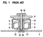
- Fig. 1 is a cross-sectional view of a conventional outer rotor radial gap-type highspeed motor.
- a conventional highspeed motor is of an outer rotor-type with radial gap. Because a stator yoke 3 is constituted by stacking up a required number of disks made of soft-magnetic steel sheets, which constitute a salient pole 6, there is a little space for winding. Therefore winding is not possible in a separate process using a bobbin or the like. Magnet wire is directly wound on the stator yoke 3 without using the bobbin and therefore a long time is required for winding process and there will be a possible deterioration of quality caused by damages on the wire. Magnetic force of a rotor magnet 7 acts principally in the radial direction, and the magnetic force in the direction of the shaft 10 is extremely weak.
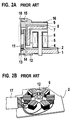
- Fig. 2A is a cross-sectional view of a conventional highspeed motor of salient pole-type with axial gap similar to the present invention
- Fig. 2B is a perspective view of a stator of the motor.
- the salient poles 6 of the stator yoke 3 have surfaces protruding in both radial and axial directions oppositely to the rotor magnet 7 fixed on a rotor yoke 8. Therefore effective magnetic flux can be extracted in abundance, thus promoting enhanced characteristics.
- the salient poles 6 are magnetically interconnected through only a base plate 1 without any magnetic circuits provided therebetween, the length of the magnetic path becomes long, and connection points become numerous, making it easy for magnetic resistance to increase, and making it impossible to further improve characteristics.
- the magnetic circuit must be made highly efficient by suppressing increase in the magnetic resistance thereof.
- a highspeed motor comprising a stator including a stator yoke and coils each arranged on each of a plurality of salient poles on said stator yoke and a rotor rotatably arranged facing the salient poles of said stator by way of an air gap
- stator yoke is constituted by a belt-shaped yoke forming ribbon, having a plurality of salient pole forming portions connected via magnetic connecting portions.
- the present invention is a directed to an highspeed motor comprising a stator including a stator yoke made of a soft magnetic material sheet and coils composed of magnetic wires wound on salient poles of said stator yoke; a rotor including a field magnet consisting of a permanent magnet so as to face said salient poles of said stator by way of an air gap and a shaft as the center of rotation in the center thereof; and a base plate having a bearing for rotatably holding said rotor in the center of said stator characterized in the stator yoke is constituted by winding a soft magnetic material sheet.
- the present invention is characterized in that there is provided on the opposite side of a salient pole of the stator yoke a protruding portion, which serves both to position and fix the stator.
- the present invention is characterized in that the height of the magnetic connecting portion for interconnecting salient poles of the yoke forming ribbon is less than one fourth of the height of a salient pole.
- the present invention is characterized in that the salient pole of the stator yoke is formed so that the width of the area facing the above-mentioned rotor is narrow on the motor shaft side, and becomes wider towards the outer circumference of the motor.
- the present invention is characterized in that the height of the salient pole of the stator yoke is formed so as to be higher on the side of the motor shaft, and to become lower towards the outer circumference of the motor.
- the present invention is characterized in that the above-mentioned stator yoke is fixed, via a bobbin wound with the above-mentioned coil, to the base plate, which supports a bearing of the above-mentioned rotor shaft.
- Fig. 3 is a cross-sectional view of a brushless DC motor for a CD-ROM of salient pole-type with axial gap as one example of a highspeed motor according to the present invention.
- a circuit board 2, with electronic components mounted thereon, is mounted on the upper surface of a base plate 1, comprising a soft-magnetic steel plate, the surface of which is rust-proofed via galvanization.
- a stator yoke 3 has on the upper side a salient pole 6, which is constituted by stacking in a winding fashion a thin, soft-magnetic material sheet (for example steel, silicon steel and pure iron etc.) and the portion 19 of the salient pole 6, which corresponds to the stator fixing portion 19 at the beginning of the winding or at the end of the winding, passes through the circuit board 2 and is fixed by caulking to the base plate 1.
- a driving coil 5 is constituted by winding a magnet wire around a bobbin 4 made of an insulating material (for example synthetic resin) and is inserted into the salient pole 6 of the stator yoke 3.
- a driving coil 5 circumferentially and the respective terminals thereof are connected to a conductor formed on the circuit board 2.
- a rotor magnet 7 opposes to the salient poles 6 of the stator yoke 3 by way of an air gap, and is affixed to a rotor yoke 8.
- a turntable 9 adapted to receive an optical disk is affixed to the upper surface of the rotor yoke 8, and in the center thereof is provided a shaft 10, which constitutes the center of rotation.
- a magnet 15 for clamping a disk is provided in the central portion of the turntable 9, and a tapered guide is provided on the periphery thereof to facilitate disk centering.
- the base plate 1 In the center portion of the base plate 1, there are provided two metal bearings 11 which hold a shaft 10 providing the center of rotation of the rotor, rotatably and coaxially with the stator yoke 3, and on the outer side thereof is a housing 12, which holds the metal bearings 11. At the base of the housing 12, there is a thrust pad 13, which props up the shaft 10 for determining the height of the turntable 9. A stopper 14 is press-fitted to the shaft 10, and prevents the turntable 9 from slipping out. On the peripheral portion of the circuit board 2, there is provided a connector 17 for electrical connection for energizing the motor driving coil 5, and the connector 17 is connected to an external motor driving circuit not shown in the drawing.
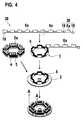
- Fig. 4 shows fabricating steps of the stator yoke 3.
- the stator yoke 3 is manufactured by rolling a belt-shaped yoke-forming ribbon 30 into a ring shape.
- the yoke-forming ribbon 30 is of a belt shape, in which salient pole-forming portions 6a of a given number (6 in the embodiment as shown) are connected via a magnetic connecting portion 18 whose height is less than one fourth of the height of the salient pole 6a, and at both ends thereof, which correspond to the beginning and the end of the winding.
- Protruding portions 19, i.e. stator fixing portions 19 are provided on the opposite side of the salient pole forming portions 6a.
- the stator fixing portions 19 serve both positioning and fixing the stator yoke 3 to the base plate 1.
- the stator yoke 3 is manufactured by rolling the belt-shaped yoke-forming ribbon 30 into a ring shape, and the salient pole-forming portions 6a are stacked together to form a given number of salient poles 6. Making the height of the magnetic connecting portion 18 less than one fourth of the height of the salient pole 6a still enables assurance of sufficient magnetic flux density from the magnetic connecting portion 18, and also facilitates rolling the yoke-forming ribbon 30 into a ring shape when manufacturing the stator yoke 3, and makes it possible to lighten the stator yoke 3, while simultaneously cutting back on material costs.
- a stator assembly is constituted by mating a hole 5a of a separately prepared coil 5 wound around a bobbin 4 to a salient pole 6 of the stator yoke 3 formed as described above. If the shape of the salient pole 6 is formed into a near trapezoidal shape here so that the width of the inner circumference side of the salient pole 6 (the motor shaft side) is narrow, and becomes wider toward the outer circumference side, it is possible to provide matching to the shape of magnetic pole of the field magnet with the result that magnetic linkage flux will be increased. Further, it is also possible to vary cogging torque and other motor characteristics by slightly deforming this shape.
- a soft magnetic material (for example steel, silicon steel etc.) plate was used for the base plate 1 in the embodiment as above exemplified, but non-magnetic material by be used.
- use of an aluminum material provides lighter weight and better heat radiation which enables improved motor characteristics.
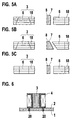
- Figs. 5A, 5B and 5C show examples of shapes of the salient pole 6 of the stator yoke 3.
- Fig. 5A is an example of a substantially trapezoidal shape whose width widens toward the outer circumference. This is effective in increasing the area facing the rotor magnet 7, and creating an abundance of effective magnetic linkage flux.
- the width of the salient pole 6 increases toward the outer circumference similar to Fig. 5A, but the height of the salient pole 6 becomes lower toward the outer circumference of the motor, and the thickness of the rotor magnet increases. This enables the realization of a rotor magnet thickness that matches magnetic pole pitch, and even more abundant effective magnetic linkage flux.
- Fig. 5C shown an example in which the salient pole 6 is made into a rectangular parallelepiped shape which enables shimplification of the shape of the bobbin.
- Fig. 6 is a cross-sectional view taken along the line A-A in Fig. 4, which shows a fixing method for the stator yoke 3.
- a protruding portion 20 is provided on the end face of the side of the bobbin 4 facing the base plate 1, and after interposing the bobbin 4 onto the stator yoke 3 beforehand, the protruding portion 20 of the bobbin 4 is inserted into the base plate 1, and then the salient poles 6 are positioned and fixed. Either press fitting or hot caulking may be applied. Further, there can be either one or two protruding portions 20. Naturally, less number of protruding portions makes working easier.
- Figs. 7A and 7B show another embodiment of a brushless DC motor of salient pole-type with an axial air gap as an example of a highspeed motor according to the present invention.
- Gig. 7A is a front view in which the case is partially cut away to show the cross section thereof
- Fig. 7B is a cross-sectional view taken along the line B-B in Fig. 7A.
- the circuit board 2 also serves as the base plate 1.
- the bearing 11 is of a twin structure, and is designed to increase rigidity relative to load in the radial direction.
- a washer is provided between the rotor yoke 8 and the case 21 to reduce frictional load at contact, but in the embodiment as shown, there is practically no play in the axial direction, eliminating the need for a washer, because the rotor magnet 7 is constantly attracted to the side of the stator yoke 3.
Landscapes
- Engineering & Computer Science (AREA)
- Power Engineering (AREA)
- Manufacturing & Machinery (AREA)
- Iron Core Of Rotating Electric Machines (AREA)
- Permanent Magnet Type Synchronous Machine (AREA)
Priority Applications (1)
| Application Number | Priority Date | Filing Date | Title |
|---|---|---|---|
| EP04012079A EP1450463B1 (fr) | 1999-02-03 | 2000-01-28 | Structure de stator d'un moteur à grande vitesse |
Applications Claiming Priority (2)
| Application Number | Priority Date | Filing Date | Title |
|---|---|---|---|
| JP2621099 | 1999-02-03 | ||
| JP02621099A JP3513042B2 (ja) | 1999-02-03 | 1999-02-03 | 高速回転型モータのステータ構造 |
Related Child Applications (1)
| Application Number | Title | Priority Date | Filing Date |
|---|---|---|---|
| EP04012079A Division EP1450463B1 (fr) | 1999-02-03 | 2000-01-28 | Structure de stator d'un moteur à grande vitesse |
Publications (3)
| Publication Number | Publication Date |
|---|---|
| EP1026809A2 true EP1026809A2 (fr) | 2000-08-09 |
| EP1026809A3 EP1026809A3 (fr) | 2001-05-23 |
| EP1026809B1 EP1026809B1 (fr) | 2007-06-06 |
Family
ID=12187091
Family Applications (2)
| Application Number | Title | Priority Date | Filing Date |
|---|---|---|---|
| EP00300674A Expired - Lifetime EP1026809B1 (fr) | 1999-02-03 | 2000-01-28 | Structure de stator d'un moteur à grande vitesse |
| EP04012079A Expired - Lifetime EP1450463B1 (fr) | 1999-02-03 | 2000-01-28 | Structure de stator d'un moteur à grande vitesse |
Family Applications After (1)
| Application Number | Title | Priority Date | Filing Date |
|---|---|---|---|
| EP04012079A Expired - Lifetime EP1450463B1 (fr) | 1999-02-03 | 2000-01-28 | Structure de stator d'un moteur à grande vitesse |
Country Status (4)
| Country | Link |
|---|---|
| US (1) | US6346759B1 (fr) |
| EP (2) | EP1026809B1 (fr) |
| JP (1) | JP3513042B2 (fr) |
| DE (2) | DE60035134T2 (fr) |
Cited By (6)
| Publication number | Priority date | Publication date | Assignee | Title |
|---|---|---|---|---|
| WO2010034082A1 (fr) | 2008-09-29 | 2010-04-01 | In Motion Technologies Pty Ltd | Agencement d'isolation d'enroulement pour machines à flux axial |
| EP2722976A3 (fr) * | 2012-10-18 | 2017-09-13 | L.H. Carbide Corporation | Ensemble de matrice et procédé de fabrication d'un article laminé pour moteur à enroulement |
| EP3804092A1 (fr) * | 2018-06-05 | 2021-04-14 | HEMA Maschinen- und Apparateschutz GmbH | Dispositif d'entraînement et fenêtre de rotation pourvue de ce dispositif d'entraînement |
| WO2023287615A1 (fr) * | 2021-07-15 | 2023-01-19 | Stoneridge, Inc. | Construction de moteur à courant continu sans balai (bldc) modulaire |
| US12095320B2 (en) | 2022-06-27 | 2024-09-17 | Anthropocene Institute LLC | Axial flux switched reluctance and inductance state machine systems, devices, and methods |
| US12149134B2 (en) * | 2022-06-27 | 2024-11-19 | Anthropocene Institute LLC | Axial flux switched reluctance motor and generator, and related systems and methods |
Families Citing this family (21)
| Publication number | Priority date | Publication date | Assignee | Title |
|---|---|---|---|---|
| JP2002153034A (ja) * | 2000-11-07 | 2002-05-24 | Sanshin Ind Co Ltd | 船外機における発電装置 |
| US6891306B1 (en) * | 2002-04-30 | 2005-05-10 | Wavecrest Laboratories, Llc. | Rotary electric motor having both radial and axial air gap flux paths between stator and rotor segments |
| US6791222B1 (en) * | 2002-04-30 | 2004-09-14 | Wavecrest Laboratories, Llc | Rotary electric motor having at least two axially air gaps separating stator and rotor segments |
| AU2003264970A1 (en) * | 2002-09-27 | 2004-04-19 | Yun-Hyun Cho | A flat board type brushless dc motor |
| JP4501919B2 (ja) * | 2003-02-26 | 2010-07-14 | 株式会社富士通ゼネラル | アキシャルギャップ型電動機 |
| JP2005185075A (ja) * | 2003-12-24 | 2005-07-07 | Fujitsu General Ltd | アキシャルギャップ型電動機 |
| JP2006136094A (ja) * | 2004-11-04 | 2006-05-25 | Funai Electric Co Ltd | 回転体駆動モータ装置とその環状マグネット組込方法 |
| TWI338433B (en) * | 2005-05-13 | 2011-03-01 | Delta Electronics Inc | Fan motor and stator thereof |
| KR101120507B1 (ko) * | 2005-12-21 | 2012-02-29 | 주식회사 동서전자 | 평편형 단상 bldc 모터 |
| US7554241B2 (en) * | 2006-03-31 | 2009-06-30 | Rao Dantam K | Three-gapped motor with outer rotor and stationary shaft |
| US20070228859A1 (en) * | 2006-03-31 | 2007-10-04 | Rao Dantam K | Gapped motor with outer rotor and stationary shaft |
| WO2009136415A2 (fr) * | 2008-05-02 | 2009-11-12 | Tvs Motor Company Limited | Machine électromécanique |
| JP4710993B2 (ja) | 2009-02-26 | 2011-06-29 | ダイキン工業株式会社 | 電機子用コア |
| US8541923B2 (en) * | 2009-03-05 | 2013-09-24 | Cpm Compact Power Motors Gmbh | Dual-rotor motor having heat dissipation |
| KR101788814B1 (ko) * | 2015-11-11 | 2017-10-20 | 엘에스오토모티브 주식회사 | 레졸버 |
| US10819178B2 (en) | 2017-01-17 | 2020-10-27 | Regal Beloit America, Inc. | Stator assembly including insulation member and method of assembly thereof |
| CN109617267B (zh) * | 2018-12-28 | 2020-12-18 | 江苏大学 | 一种适用于混合动力汽车的裂槽式磁场调制永磁电机 |
| AT522711A1 (de) * | 2019-07-09 | 2021-01-15 | Miba Sinter Austria Gmbh | Stator für eine Axialflussmaschine |
| FR3144719A1 (fr) * | 2022-12-28 | 2024-07-05 | Renault S.A.S | Stator pour machine électrique à flux axial et procédé d’obtention d’un tel stator |
| CN116865507B (zh) * | 2023-07-26 | 2024-01-16 | 江苏大中技术股份有限公司 | 一种高效率电机定子线圈自动嵌入装置 |
| CN119420098B (zh) * | 2025-01-06 | 2025-04-22 | 东莞市驰驱电机有限公司 | 一种高效风能转换装置 |
Family Cites Families (22)
| Publication number | Priority date | Publication date | Assignee | Title |
|---|---|---|---|---|
| US3886256A (en) * | 1971-07-30 | 1975-05-27 | Hitachi Ltd | Stator core for rotary electric machines and method of manufacturing the same |
| US4187441A (en) | 1977-03-23 | 1980-02-05 | General Electric Company | High power density brushless dc motor |
| US4578610A (en) | 1978-06-12 | 1986-03-25 | General Electric Company | Synchronous disk motor with amorphous metal stator and permanent magnet rotor and flywheel |
| JPS5517246A (en) | 1978-07-19 | 1980-02-06 | Matsushita Electric Ind Co Ltd | Manufacturing method of conical motor core |
| JPS607901B2 (ja) | 1979-09-28 | 1985-02-27 | 松下電器産業株式会社 | 偏平形電動機の巻鉄心加工法 |
| US4394597A (en) | 1980-09-15 | 1983-07-19 | Allied Corporation | Multiple pole axial field electromagnetic devices |
| GB2127231B (en) | 1982-07-27 | 1987-08-19 | Papst Motoren Gmbh & Co Kg | Drive motor unit for signal-processing devices especially information-storage-disk devices |
| JPS6051426A (ja) | 1983-08-26 | 1985-03-22 | Matsushita Electric Ind Co Ltd | 軸方向空隙誘導電動機 |
| JPS6135150A (ja) * | 1984-07-25 | 1986-02-19 | Fujitsu Ltd | コイルボビン固定構造 |
| US4654552A (en) * | 1985-03-28 | 1987-03-31 | General Electric Company | Lanced strip and edgewise wound core |
| US4647802A (en) * | 1985-06-13 | 1987-03-03 | Hewlett-Packard Company | Variable reluctance motor with reduced torque ripple |
| US4959578A (en) * | 1987-11-24 | 1990-09-25 | Axial Electric, Inc. | Dual rotor axial air gap induction motor |
| US4949000A (en) * | 1988-07-18 | 1990-08-14 | Mueller And Smith, Lpa | D.C. motor |
| US5028830A (en) * | 1989-07-24 | 1991-07-02 | Allied-Signal Inc. | Rotor apparatus for axial field electromagnetic devices |
| US5208503A (en) * | 1991-04-12 | 1993-05-04 | Hisey Bradner L | Energy-efficient ferromagnetic stator and core apparatus |
| WO1993010593A1 (fr) * | 1991-11-13 | 1993-05-27 | Seiko Epson Corporation | Moteur a courant continu sans balais |
| JPH0654489A (ja) | 1992-07-29 | 1994-02-25 | Sankyo Seiki Mfg Co Ltd | 回転電機の積層コア |
| US5519270A (en) | 1992-08-19 | 1996-05-21 | Fujitsu Limited | Spindle motor and disk drive having the same |
| US5465020A (en) * | 1994-01-07 | 1995-11-07 | Tri-Tech, Inc. | Integral shaft bearing and bobbin for electric motors |
| FR2739505B1 (fr) * | 1995-09-29 | 1997-12-19 | Technicatome | Moteur electrique asynchrone discoidal |
| US5925965A (en) * | 1996-09-06 | 1999-07-20 | Emerson Electric Co. | Axial flux reluctance machine with two stators driving a rotor |
| US5731649A (en) * | 1996-12-27 | 1998-03-24 | Caama+E,Otl N+Ee O; Ramon A. | Electric motor or generator |
-
1999
- 1999-02-03 JP JP02621099A patent/JP3513042B2/ja not_active Expired - Fee Related
-
2000
- 2000-01-26 US US09/491,825 patent/US6346759B1/en not_active Expired - Fee Related
- 2000-01-28 EP EP00300674A patent/EP1026809B1/fr not_active Expired - Lifetime
- 2000-01-28 DE DE60035134T patent/DE60035134T2/de not_active Expired - Lifetime
- 2000-01-28 DE DE60035080T patent/DE60035080T2/de not_active Expired - Lifetime
- 2000-01-28 EP EP04012079A patent/EP1450463B1/fr not_active Expired - Lifetime
Cited By (12)
| Publication number | Priority date | Publication date | Assignee | Title |
|---|---|---|---|---|
| WO2010034082A1 (fr) | 2008-09-29 | 2010-04-01 | In Motion Technologies Pty Ltd | Agencement d'isolation d'enroulement pour machines à flux axial |
| CN102239623A (zh) * | 2008-09-29 | 2011-11-09 | 动态技术股份有限公司 | 用于轴向磁通电机的绕组绝缘装置 |
| EP2329583A4 (fr) * | 2008-09-29 | 2013-01-02 | In Motion Technologies Pty Ltd | Agencement d'isolation d'enroulement pour machines à flux axial |
| CN102239623B (zh) * | 2008-09-29 | 2015-06-03 | 动态技术股份有限公司 | 用于轴向磁通电机的绕组绝缘装置 |
| US9780616B2 (en) | 2008-09-29 | 2017-10-03 | Regal Beloit Australia Pty. Ltd. | Winding insulation arrangement for axial flux machines |
| EP2722976A3 (fr) * | 2012-10-18 | 2017-09-13 | L.H. Carbide Corporation | Ensemble de matrice et procédé de fabrication d'un article laminé pour moteur à enroulement |
| EP3804092A1 (fr) * | 2018-06-05 | 2021-04-14 | HEMA Maschinen- und Apparateschutz GmbH | Dispositif d'entraînement et fenêtre de rotation pourvue de ce dispositif d'entraînement |
| WO2023287615A1 (fr) * | 2021-07-15 | 2023-01-19 | Stoneridge, Inc. | Construction de moteur à courant continu sans balai (bldc) modulaire |
| US11658530B2 (en) | 2021-07-15 | 2023-05-23 | Stoneridge, Inc. | Modular brushless DC (BLDC) motor construction |
| US12095320B2 (en) | 2022-06-27 | 2024-09-17 | Anthropocene Institute LLC | Axial flux switched reluctance and inductance state machine systems, devices, and methods |
| US12149134B2 (en) * | 2022-06-27 | 2024-11-19 | Anthropocene Institute LLC | Axial flux switched reluctance motor and generator, and related systems and methods |
| US12580465B2 (en) | 2022-06-27 | 2026-03-17 | Anthropocene Institute LLC | Axial flux switched reluctance and inductance state machine systems, devices, and methods |
Also Published As
| Publication number | Publication date |
|---|---|
| EP1450463B1 (fr) | 2007-06-06 |
| EP1026809A3 (fr) | 2001-05-23 |
| EP1450463A1 (fr) | 2004-08-25 |
| US6346759B1 (en) | 2002-02-12 |
| DE60035134D1 (de) | 2007-07-19 |
| JP3513042B2 (ja) | 2004-03-31 |
| EP1026809B1 (fr) | 2007-06-06 |
| DE60035080D1 (de) | 2007-07-19 |
| DE60035080T2 (de) | 2008-02-07 |
| JP2000224784A (ja) | 2000-08-11 |
| DE60035134T2 (de) | 2008-02-07 |
Similar Documents
| Publication | Publication Date | Title |
|---|---|---|
| US6346759B1 (en) | Stator structure of highspeed motor | |
| US6157112A (en) | Brushless DC motor structure | |
| US5739614A (en) | Two-phase unipolar driving brushless DC motor | |
| EP1047177B1 (fr) | Moteur miniature et son procédé de fabrication | |
| US20080129139A1 (en) | Spindle motor | |
| JP3535012B2 (ja) | ラジアルギャップ型小型円筒型回転電機 | |
| US20020190602A1 (en) | Motor structure | |
| CN100536292C (zh) | 无刷电动机 | |
| JPH11146616A (ja) | モータ構造 | |
| US6661150B2 (en) | Motor having stator with L-shaped salient poles | |
| JPH06296353A (ja) | スピンドルモータ | |
| JP3396753B2 (ja) | ブラシレスdcモータの軸受け構造 | |
| JP3431854B2 (ja) | ブラシレス直流モーター及びそのステーター | |
| US5739620A (en) | Optimum groove/pole ratio for brushless motor stator profile | |
| JPH1198792A (ja) | インナーロータモータ | |
| JP2591448Y2 (ja) | ブラシレスモータのステータ装置 | |
| JP2000245080A (ja) | ブラシレスモータ | |
| JPH07245926A (ja) | ブラシレスモータ | |
| JPS60128838A (ja) | 軸方向空隙型誘導電動機 | |
| JP2000197332A (ja) | ステ―タコアおよびモ―タ | |
| JP3707027B2 (ja) | マイクロ扁平振動モータの最適化構造 | |
| JPH06245462A (ja) | モータ | |
| JP2591945Y2 (ja) | ブラシレスモータ | |
| KR200212480Y1 (ko) | 비엘디씨 모터 | |
| JP2000197333A (ja) | モ―タ |
Legal Events
| Date | Code | Title | Description |
|---|---|---|---|
| PUAI | Public reference made under article 153(3) epc to a published international application that has entered the european phase |
Free format text: ORIGINAL CODE: 0009012 |
|
| AK | Designated contracting states |
Kind code of ref document: A2 Designated state(s): DE FR |
|
| AX | Request for extension of the european patent |
Free format text: AL;LT;LV;MK;RO;SI |
|
| RIN1 | Information on inventor provided before grant (corrected) |
Inventor name: FUJITANI, SAKAE, C/O MINEBEA CO., LTD. Inventor name: HARADA, NAOYUKI, C/O MINEBEA CO., LTD. Inventor name: SUZUKI, YUZURU, C/O MINEBEA CO., LTD. Inventor name: OHYASHIKI, TAKETOSHI, C/O MINEBEA CO., LTD. |
|
| PUAL | Search report despatched |
Free format text: ORIGINAL CODE: 0009013 |
|
| AK | Designated contracting states |
Kind code of ref document: A3 Designated state(s): AT BE CH CY DE DK ES FI FR GB GR IE IT LI LU MC NL PT SE |
|
| AX | Request for extension of the european patent |
Free format text: AL;LT;LV;MK;RO;SI |
|
| 17P | Request for examination filed |
Effective date: 20011116 |
|
| AKX | Designation fees paid |
Free format text: DE FR |
|
| 17Q | First examination report despatched |
Effective date: 20020614 |
|
| GRAP | Despatch of communication of intention to grant a patent |
Free format text: ORIGINAL CODE: EPIDOSNIGR1 |
|
| GRAS | Grant fee paid |
Free format text: ORIGINAL CODE: EPIDOSNIGR3 |
|
| GRAA | (expected) grant |
Free format text: ORIGINAL CODE: 0009210 |
|
| AK | Designated contracting states |
Kind code of ref document: B1 Designated state(s): DE FR |
|
| REF | Corresponds to: |
Ref document number: 60035080 Country of ref document: DE Date of ref document: 20070719 Kind code of ref document: P |
|
| ET | Fr: translation filed | ||
| PLBE | No opposition filed within time limit |
Free format text: ORIGINAL CODE: 0009261 |
|
| STAA | Information on the status of an ep patent application or granted ep patent |
Free format text: STATUS: NO OPPOSITION FILED WITHIN TIME LIMIT |
|
| 26N | No opposition filed |
Effective date: 20080307 |
|
| PGFP | Annual fee paid to national office [announced via postgrant information from national office to epo] |
Ref country code: FR Payment date: 20080211 Year of fee payment: 9 |
|
| REG | Reference to a national code |
Ref country code: FR Ref legal event code: ST Effective date: 20091030 |
|
| PG25 | Lapsed in a contracting state [announced via postgrant information from national office to epo] |
Ref country code: FR Free format text: LAPSE BECAUSE OF NON-PAYMENT OF DUE FEES Effective date: 20090202 |
|
| PGFP | Annual fee paid to national office [announced via postgrant information from national office to epo] |
Ref country code: DE Payment date: 20110126 Year of fee payment: 12 |
|
| PG25 | Lapsed in a contracting state [announced via postgrant information from national office to epo] |
Ref country code: DE Free format text: LAPSE BECAUSE OF NON-PAYMENT OF DUE FEES Effective date: 20120801 |
|
| REG | Reference to a national code |
Ref country code: DE Ref legal event code: R119 Ref document number: 60035080 Country of ref document: DE Effective date: 20120801 |