EP1030751B1 - Ziehstanzwerkzeug zum stanzen von fahrzeug-karosseriewänden - Google Patents
Ziehstanzwerkzeug zum stanzen von fahrzeug-karosseriewänden Download PDFInfo
- Publication number
- EP1030751B1 EP1030751B1 EP98948636A EP98948636A EP1030751B1 EP 1030751 B1 EP1030751 B1 EP 1030751B1 EP 98948636 A EP98948636 A EP 98948636A EP 98948636 A EP98948636 A EP 98948636A EP 1030751 B1 EP1030751 B1 EP 1030751B1
- Authority
- EP
- European Patent Office
- Prior art keywords
- die
- sheet metal
- central
- sheet
- assembly
- Prior art date
- Legal status (The legal status is an assumption and is not a legal conclusion. Google has not performed a legal analysis and makes no representation as to the accuracy of the status listed.)
- Expired - Lifetime
Links
- 239000002184 metal Substances 0.000 claims description 126
- 230000002093 peripheral effect Effects 0.000 claims description 85
- 239000007769 metal material Substances 0.000 claims description 29
- 239000011324 bead Substances 0.000 claims description 15
- 238000000034 method Methods 0.000 claims description 15
- 238000010422 painting Methods 0.000 claims description 4
- 230000000712 assembly Effects 0.000 claims description 3
- 238000000429 assembly Methods 0.000 claims description 3
- 238000005452 bending Methods 0.000 claims description 2
- 239000000463 material Substances 0.000 description 4
- IJGRMHOSHXDMSA-UHFFFAOYSA-N Atomic nitrogen Chemical compound N#N IJGRMHOSHXDMSA-UHFFFAOYSA-N 0.000 description 2
- 238000004519 manufacturing process Methods 0.000 description 2
- 206010040925 Skin striae Diseases 0.000 description 1
- 229910000831 Steel Inorganic materials 0.000 description 1
- 208000031439 Striae Distensae Diseases 0.000 description 1
- 238000005516 engineering process Methods 0.000 description 1
- 229910052757 nitrogen Inorganic materials 0.000 description 1
- 230000000284 resting effect Effects 0.000 description 1
- 239000010959 steel Substances 0.000 description 1
- 238000005482 strain hardening Methods 0.000 description 1
- 230000007704 transition Effects 0.000 description 1
Images





Classifications
-
- B—PERFORMING OPERATIONS; TRANSPORTING
- B21—MECHANICAL METAL-WORKING WITHOUT ESSENTIALLY REMOVING MATERIAL; PUNCHING METAL
- B21D—WORKING OR PROCESSING OF SHEET METAL OR METAL TUBES, RODS OR PROFILES WITHOUT ESSENTIALLY REMOVING MATERIAL; PUNCHING METAL
- B21D22/00—Shaping without cutting, by stamping, spinning, or deep-drawing
- B21D22/02—Stamping using rigid devices or tools
-
- B—PERFORMING OPERATIONS; TRANSPORTING
- B21—MECHANICAL METAL-WORKING WITHOUT ESSENTIALLY REMOVING MATERIAL; PUNCHING METAL
- B21D—WORKING OR PROCESSING OF SHEET METAL OR METAL TUBES, RODS OR PROFILES WITHOUT ESSENTIALLY REMOVING MATERIAL; PUNCHING METAL
- B21D22/00—Shaping without cutting, by stamping, spinning, or deep-drawing
- B21D22/02—Stamping using rigid devices or tools
- B21D22/06—Stamping using rigid devices or tools having relatively-movable die parts
Definitions
- the present invention relates to stamping dies and methods for stamping sheet metal to for outer body panels for motor vehicles.
- draw forming or draw stamping sheet metal that can be used for outer body panels has been commercially unsuccessful.
- the draw forming and stamping operations have conventionally produced parts that are not suited to be used for applications requiring "class A" surface finishes, such as what is required for outer body panels.
- conventional draw forming operations impart stretch marks, scratches, and other irregularities to the part that make the part unsuitable for exterior body panels.
- Document FR-A-2 646 623 discloses the features set out in the preambles of claims 1 and 8, respectively.
- a die assembly for draw stamping sheet metal in a press for forming an exterior body panel for a motor vehicle, as defined in claim 1.
- the die assembly comprises a first die assembly including a central first die structure that engages one surface of the sheet metal during a stamping operation.
- the first die assembly further includes a movable peripheral clamping structure which is movable with respect to the first die structure and constructed and arranged to engage first peripheral portion of the sheet metal.
- a second die assembly is provided and includes a second die structure having a central stamping surface that engages an opposite surface of the sheet metal during the stamping operation.
- the second die structure includes a peripheral clamping surface constructed and arranged to cooperate with the movable clamping structure to clamp the first peripheral portion of the sheet metal therebetween.
- the second die assembly further includes a movable die pad which is movable with respect to the second die structure.
- the movable die pad is cooperable with the first die structure to clamp second peripheral portion of the sheet metal therebetween.
- the second die assembly is movable by a press so that the peripheral clamping surface thereof cooperates with the movable clamping structure of the first die assembly to clamp the first peripheral portion of the sheet metal therebetween.
- the peripheral clamping surface and the movable clamping structure are moved with the first portions of sheet metal clamped therebetween to deform the sheet metal over the central first die structure.
- the movable die pad is movable relative to the second die structure and towards the first die structure so as to clamp the second portions of the sheet metal between the movable die pad and the first die structure after the sheet metal is deformed over the central first die structure.
- the peripheral clamping surface and the movable clamping structure can be moved to stretch the sheet metal over the central first die structure, and the central stamping surface is cooperable with the central first die structure of the second die structure to stamp the sheet metal therebetween after the sheet metal has been stretched over the central first die structure so as to provide the sheet metal with a desired configuration.
- a method for forming exterior body panels for a motor vehicle as defined in claim 8.
- the present invention provides a method comprising mounting a sheet of metal material in a die assembly, clamping first peripheral portion of the sheet of metal material between clamping surfaces of the die assembly, moving the clamping surfaces relative to a central die structure so as to deform the sheet metal over the central die structure, clamping second peripheral portion of the sheet of metal material between a die pad of the die assembly and the central die structure after the sheet metal is deformed over the central die structure, moving the clamping surfaces relative to the central die structure to stretch the sheet metal over the central die structure after the second peripheral portion of the sheet of metal material are clamped, and stamping the sheet of metal material between the central structure and an opposing die surface after the sheet metal has been stretched over the die structure so as to provide the sheet metal with a desired configuration.
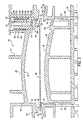
- the sheet metal forming die assembly 10 (known as a deep draw assembly) includes first and second die assemblies.
- the first die assembly is a lower die assembly 14, and the second die assembly is an upper die assembly 12 which cooperate to form the metal sheet material 16 positioned therebetween.
- the sheet metal blank 16 has a substantially four-sided, rectangular configuration. It should be appreciated, however, that the present invention is not limited to sheet metal blanks of such configuration.
- the upper die assembly 12 is mounted in a conventional hydraulic of press (not shown) to enable upwards and downwards movement of the upper die assembly 12.
- the lower die assembly 14 includes a lower horizontal support member or die shoe 22.
- a fixed dome-shaped central portion or die structure 24 of the lower die assembly 14 is carried by the lower die shoe 22.
- the fixed central die structure 24 has an upwardly facing die surface 26 in accordance with the desired shape of the sheet metal 16.
- a movable peripheral portion or clamping structure 28 of lower die assembly 14 surrounds the fixed central die structure 24 and is mounted on pneumatic spring members 30 extending upwardly from the lower die shoe 22.
- the spring members 30 bias the peripheral clamping structure 28 in an upwards direction.
- the movable peripheral clamping structure 28 has an upper surface 29, which is disposed slightly higher than the upper surface 26 of the structure 24 when the assembly is at rest (e.g. in Figures 1 and 2).
- hardened steal wear plates 32 provided at the interface between the movable peripheral clamping structure 28 and the fixed central die structure 24 serve to provide conventional guide and wear surfaces.
- the periphery of the sheet metal 16 is mounted onto the upper surface 29 of the movable peripheral clamping structure 28. More specifically, as can be appreciated from Figure 1, the upper surface 29 has three upwardly facing peripheral surface areas 34, 35, and 36 which are constructed and arranged to engage the underside of the sheet metal adjacent three peripheral edges 31 of sheet metal 16.
- a fourth peripheral surface area 37 extends beyond the adjacent edge of the sheet metal 16 when the sheet metal 16 is properly mounted in the assembly 10.
- one edge 33 of the sheet metal is left suspended above the fixed central structure 24.
- the three peripheral edges 31 constitute a first peripheral portion of the sheet metal 16, while the fourth peripheral edge 33 constitutes a second peripheral portion of the sheet metal 16, which first and second portions of sheet metal are formed different in the die assembly 10, as will be described.
- a groove 38 is formed in the aforementioned three surface areas 34, 35, and 36 of the movable peripheral clamping structure 28.
- the upper die assembly 12 has a peripheral portion 44 and a central portion 48.
- the peripheral portion 44 has a downwardly facing peripheral clamping surface 42 which forms a raised locking bead 40.
- the bead 40 is provided along three surface areas of the upper peripheral clamping surface 42 which are constructed and arranged to engage the three surface areas 34, 35, and 36 of the movable peripheral clamping structure 28.
- the bead 40 is disposed directly above the groove 38 and has substantially the same shape.
- the bead 40 and groove 38 come together in form-locking relation so as to lock a first peripheral portion of the sheet metal, including three peripheral sides 31 of the sheet metal 16 therebetween when the upper die assembly 12 is lowered.
- the central portion 48 of upper die assembly 12 has a downwardly facing upper die stamping surface 50 surrounded by a vertical peripheral surface 52.
- the upper die surface 50 and lower die surface 26 have substantially inverted configuration with respect to one another so that the upper die surface 50 cooperates with the lower die surface 26 to stamp and form the central portion of the sheet metal material 16 therebetween when the upper die assembly 12 is lowered (e.g., see Figure 5).
- the upper die assembly 12 comprises a main upper die structure 13 an independently movable upper die pad assembly generally shown at 54. More specifically, the movable upper die pad assembly 54 is received within a recess 55 in central portion 48 of the upper die structure 13.
- the movable upper die pad assembly 54 is attached to upper die structure 13 by means of an upper mounting plate 56.
- pneumatic cylinder members, preferably nitrogen spring cylinders, 58 are directly attached to the upper mounting plate 56 and extend vertically downwardly therefrom.
- Each pneumatic cylinder 58 comprises an upper cylinder portion 60 that telescopically receives a piston rod 62.
- the lower end of the piston rod 62 is attached to a pressure plate 64.
- a steel pressure die pad 66 of the movable upper die pad assembly 54 has a generally U-shaped cross-section defining an interior space 69 within which the cylinders 58 are received.
- the U-shaped section is defined by vertical walls 68 and 70 and horizontal base 72.
- the pressure plate 64 is attached interiorally to an inner surface 76 of the base 72 and forms the interconnection between the cylinders 58 and the die pad element 66.
- the parallel walls 68 and 70 of the movable die pad element 66 have wear plates 78 along their outer surface which cooper the with wear plates 80 along the surfaces defining the recess 55 in the upper die central portion 48 to guide and direct the movable die pad 66.
- the movable pad element 66 includes a lower die surface 86 which includes a raised locking bead 88.
- the locking bead 88 is positioned directly above a longitudinal groove 90 that is formed along the upper surface 26 of fixed die structure 24 at a position adjacent the fourth surface area 37 of the movable peripheral clamping structure 28 of the lower die assembly.
- the groove 90 is disposed under a peripheral side portion of the sheet metal 16 adjacent edge 33 and cooperates with the locking bead 88 to lock the aforementioned peripheral position of the sheet metal 16 therebetween as will be described in greater detail later.
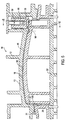
- the pad element 66 engages and clamps the fourth portion adjacent edge 33 of sheet metal 16 against the upper surface 26 of the fixed central die member 24 ash shown in Figure 4. This locking or clamping of the fourth peripheral portion of sheet metal 16 is facilitated by the cooperating locking bead 88 and groove 90.
- the movable die pad element 66 engages the peripheral portion adjacent edge 33 of the sheet metal 16 which is formed into a portion of the final stamped product which is not provided with any significant structural depth, and in any event, less structural depth than the other three edge portions 31, and thus need not be stretched to any significant extent.
- locking bead 88 and groove 90 arrangement and the locking bead 40 and groove 38 arrangement operate such that stretching of the central portion of sheet metal 16 over fixed die structure 24 is substantially limited to portions of the sheet metal within the four line boundaries defined by these locking beads and grooves.
- the present invention provides a die assembly 10 for draw stamping sheet metal 16 in a press for forming an exterior body panel for a motor vehicle.
- the die assembly includes a first die assembly 14 including a central first die structure 24 constructed and arranged to engage one surface of the sheet metal during a stamping operation.
- the first die assembly 14 further includes a movable peripheral clamping structure 28 which is movable with respect to the first die structure 24 and constructed and arranged to engage first peripheral portion 31 of the sheet metal 16.
- the second die assembly 12 includes a second die structure 13 having a central stamping surface 50 constructed and arranged to engage an opposite surface of the sheet metal 16 during the stamping operation.
- the second die structure 13 includes a peripheral clamping surface 42 constructed and arranged to cooperate with the movable clamping structure 28 to clamp the first peripheral portion 31 of the sheet metal 16 therebetween.
- the second die assembly further includes a movable die pad assembly 54 which is movable with respect to the second die structure 13.
- the movable die pad assembly 54 is cooperable with the first die structure 24 to clamp second peripheral portion 33 of the sheet metal 16 therebetween.
- the first and second die assemblies 14 and 12, respectively, are constructed and arranged to be mounted in a press, the second die assembly 12 being movable by the press so that the peripheral clamping surface 42 thereof cooperates with the movable clamping structure 28 of the first die assembly 14 to clamp the first peripheral portion 31 of the sheet metal 16 therebetween.
- the peripheral clamping surface 42 and the movable clamping structure 28 are moved with the first peripheral portion 31 of sheet metal clamped therebetween to deform the sheet metal 16 over the central first die structure 24.
- the movable die pad assembly 54 is movable relative to the second die structure 13 and towards the first die structure 24 so as to clamp the second peripheral portion 33 of the sheet metal 16 between the movable die pad assembly 54 and the first die structure 24 after the sheet metal is deformed over the central first die structure 24.
- the peripheral clamping surface 42 and the movable clamping structure 28 are movable to stretch the sheet metal over the central first die structure 24.
- the central stamping surface 50 is cooperable with the central first die structure 24 to stamp the sheet metal therebetween after the sheet metal has been stretched over the central first die structure 24 so as to provide the sheet metal with a desired configuration.
- the initial stretching and forming of sheet metal 16 as shown in Figure 3 occurs sometime before the movable element 66 engages and locks the sheet metal 16 at peripheral portion adjacent edge 33.
- This order of engagement is important in order to preserve and maintain the ornamental nature of the finished sheet metal product which can be used as a class A motor vehicle body outer panel.
- the die assembly in accordance with the present invention is particularly constructed and arranged to minimize surface skid marks and scratches that can occur during the stamping and stretching process, and is also constructed and arranged to reduce, or prevent distortion of the panel, which would be unsuitable for the final surface finish, including painting, of class A outer panel requirements.
- FIG 7 is a perspective view of a preferred exterior body panel made in accordance with the present invention.
- the body panel is in the form of a rear side panel generally indicated at 108 for the rear box of a pick-up truck. After the sheet metal is stamped or drawn, it is cut and formed into its final configuration. For example, a wheel opening 110 and an opening 112 for a rear light is formed.
- the front end portion of the panel 108 is formed into a flange 114, as can be appreciated from the cross-sectional view in Figure 8, taken through line 8-8 in Figure 7. It can be appreciated from Figure 8 that the flange 114 is formed by bending the end portion 116 of the sheet metal after it has been cut off along line 98.
- the exterior surface 118 of the flange 114 is mated to a rear surface on the cab portion of a pick-up truck.
- the sheet metal is then painted in a conventional painting station, together with the rest of the vehicle.
Landscapes
- Engineering & Computer Science (AREA)
- Mechanical Engineering (AREA)
- Shaping Metal By Deep-Drawing, Or The Like (AREA)
Claims (18)
- Werkzeugvorrichtung zum Ziehpressen von Blechen in einer Presse zur Formung eines äusseren Karosserieblechs, wobei die Werkzeugvorrichtung umfasstwobeieine erste Werkzeugvorrichtung (14), die eine erste Werkzeugeinrichtung (24) aufweist, die so aufgebaut und angeordnet ist, dass sie an einer Oberfläche des Bleches während eines Pressvorgangs angreift, wobei die erste Werkzeugvorrichtung außerdem eine bewegbare Umfangsklemmeinrichtung (28) aufweist, die bezüglich der ersten Werkzeugeinrichtung (24) bewegbar ist und so aufgebaut und angeordnet ist, dass sie an einem ersten Umfangsabschnitt des Bleches angreift,eine zweite Werkzeugvorrichtung (12), die eine zweite Werkzeugeinrichtung mit einer zentralen Pressfläche (48) aufweist, die so aufgebaut und angeordnet ist, dass sie an einer entgegengesetzten Oberfläche des Bleches während des Pressvorgangs angreift, wobei die zweite Werkzeugeinrichtung eine Umfangsklemmfläche (42) aufweist, die so aufgebaut und angeordnet ist, dass sie mit der bewegbaren Klemmeinrichtung (28) zusammenwirkt, um den ersten Umfangsabschnitt des Bleches dazwischen zu klemmen,wobei die zweite Werkzeugvorrichtung (12) außerdem eine bewegbare Werkzeugkissenvorrichtung (54) aufweist, die bezüglich der zweiten Werkzeugeinrichtung bewegbar ist, wobei die bewegbare Werkzeugkissenvorrichtung (54) mit der ersten Werkzeugeinrichtung (24) zusammenwirken kann, um einen zweiten Umfangsabschnitt des Bleches dazwischen zu klemmen,dadurch gekennzeichnet, dassdie erste und zweite Werkzeugvorrichtung (12, 14) so aufgebaut und angeordnet sind, dass sie in einer Presse angebarcht werden können, unddie zentrale Pressfläche mit der zentralen ersten Werkzeugeinrichtung (24) zusammenwirken kann, um das Blech dazwischen zu pressen, nachdem das Blech über die zentrale erste Werkzeugeinrichtung (24) gestreckt wurde, um das Blech mit einer gewünschten Form zu versehen,die zweite Werkzeugvorrichtung (12) so durch die Presse bewegbar ist, dass ihre Umfangsklemmfläche (42) mit der bewegbaren Klemmeinrichtung (28) der ersten Werkzeugvorrichtung zusammenwirkt, um den ersten Umfangsabschnitt des Bleches dazwischen zu klemmen,die Umfangsklemmfläche (42) und die bewegbare Klemmeinrichtung (28) mit den ersten Abschnitten des dazwischengeklemmten Bleches bewegt werden, um das Blech über der zentralen ersten Werkzeugeinrichtung (24) zu verformen, die bewegbare Werkzeugkissenvorrichtung (54) relativ zu der zweiten Werkzeugeinrichtung und in Richtung der ersten Werkzeugeinrichtung (24) bewegbar ist, um die zweiten Abschnitte des Bleches zwischen der bewegbaren Werkzeugkissenvorrichtung (54) und der ersten Werkzeugeinrichtung (24) zu klemmen, nachdem das Blech über der zentralen ersten Werkzeugeinrichtung (24) verformt wurde, unddie Umfangsklemmfläche (42) und die bewegbare Klemmeinrichtung (28) zur Streckung des Bleches über der zentralen ersten Werkzeugeinrichtung bewegt werden.
- Werkzeugvorrichtung nach Anspruch 1, wobei die Werkzeugkissenvorrichtung (54) ein Werkzeugkissen und wenigstens ein Federelement (58) aufweist, durch das das Werkzeugkissen für eine Bewegung relativ zu der zweiten Werkzeugeinrichtung angebracht ist.
- Werkzeugvorrichtung nach Anspruch 2, wobei die erste Werkzeugvorrichtung (14) außerdem mehrere Federelemente (30) umfasst, durch die die bewegbare Klemmeinrichtung für eine Bewegung angebracht ist.
- Werkzeugvorrichtung nach Anspruch 3, wobei die zweite Werkzeugeinrichtung (12) so aufgebaut und angeordnet ist, dass sie an einer oberen Pressenramme befestigt werden kann und im Einsatz abgesenkt wird, bis ihre Klemmfläche (48) an dem Blech angreift und das Blech gegen die bewegbare Klemmeinrichtung (28) klemmt, und wobei ein fortgesetztes Absenken der zweiten Werkzeugeinrichtung eine Bewegung der bewegbaren Klemmeinrichtung (28) nach unten gegen die Vorspannung der mehreren Federelemente (30) verursacht, bis das Blech über der zentralen ersten Werkzeugeinrichtung verformt wurde.
- Werkzeugvorrichtung nach Anspruch 4, wobei das Werkzeugkissen (54) gegen eine Federspannung wenigstens eines Federelements (58) bewegt wird, nachdem das Werkzeugkissen das Blech gegen die erste Werkzeugeinrichtung (24) klemmt.
- Werkzeugvorrichtung nach Anspruch 2, wobei die zweite Werkzeugeinrichtung (12) eine Ausnehmung (55) aufweist, und wobei das wenigstens eine Federelement (58) und das Werkzeugkissen (54) innerhalb der Ausnehmung (55) angeordnet sind.
- Werkzeugvorrichtung nach Anspruch 6, wobei die zweite Werkzeugeinrichtung (12) eine Befestigungsplatte (56) innerhalb der Ausnehmung (55) aufweist, und wobei ein Ende des wenigstens einen Federelements (58) an der Befestigungsplatte (56) befestigt ist, und wobei ein entgegengesetztes Ende des wenigstens einen Federelements (58) an dem Werkzeugkissen (54) befestigt ist.
- Verfahren zum Formen eines äußeren Karosserieblechs für ein Kraftfahrzeug, bei demdadurch gekennzeichnet, dassein Blech in einer Werkzeugvorrichtung (12, 14) angebracht wird,ein erster Umfangsabschnitt des Bleches zwischen Klemmflächen der Werkzeugvorrichtung (28, 42) geklemmt wird,die Klemmflächen relativ zu einer zentralen Werkzeugeinrichtung (24) bewegt werden, um das Blech über der zentralen Werkzeugeinrichtung (24) zu verformen,ein zweiter Umfangsabschnitt des Bleches zwischen einem Werkzeugkissen (54) der Werkzeugvorrichtung und der zentralen Werkzeugeinrichtung (24) geklemmt wird, nachdem das Blech über der zentralen Werkzeugeinrichtung verformt wurde,die Klemmflächen (28, 42) relativ zu der zentralen Werkzeugeinrichtung (24) bewegt werden, um das Blech über der zentralen Werkzeugeinrichtung zu strecken, nachdem der zweite Umfangsabschnitt des Bleches geklemmt wurde, das Blech zwischen der zentralen Einrichtung (24) undeiner gegenüberliegenden Werkzeugfläche (48) gepresst wird, nachdem das Blech über die Werkzeugeinrichtung gestreckt wurde, um das Blech mit einer gewünschten Form zu versehen.
- Verfahren nach Anspruch 8, bei dem außerdem nach dem Pressen das Blech lackiert wird.
- Verfahren nach Anspruch 8, bei dem die Werkzeugvorrichtung eine untere Werkzeugvorrichtung und eine obere Werkzeugvorrichtung (14, 12) umfasst, und die Klemmflächen der Werkzeugvorrichtung untere Klemmflächen (28), die auf einer bewegbaren Umfangsklemmeinrichtung der unteren Werkzeugvorrichtung vorgesehen sind, und obere Klemmflächen (42) umfasst, die auf der oberen Werkzeugvorrichtung vorgesehen sind,
wobei das Klemmen des ersten Umfangsabschnitts durch Absenkung der oberen Werkzeugvorrichtung (12) so durchgeführt wird, dass ihre oberen Klemmflächen (42) in Richtung der unteren Klemmflächen (28) bewegt werden, um den ersten Umfangsabschnitt des Bleches dazwischenzuklemmen. - Verfahren nach Anspruch 10, wobei die Verformung des Bleches über der zentralen Werkzeugeinrichtung (24) durch Bewegung der oberen Werkzeugvorrichtung (12) und der Unfangsklemmeinrichtung der unteren Werkzeugvorrichtung relativ zu der zentralen Werkzeugeinrichtung (24) durchgeführt wird, während der erste Umfangsabschnitt des Bleches zwischen den oberen und unteren Klemmflächen (28, 42) geklemmt ist, sodass eine Seite des Bleches so verformt wird, dass es an einer oberen Fläche der zentralen Werkzeugeinrichtung insgesamt konform angreift.
- Verfahren nach Anspruch 11, wobei das Werkzeugkissen (54) mit der oberen Werkzeugvorrichtung (12) verbunden ist, und die zentrale Werkzeugeinrichtung (24) einen Teil der unteren Werzeugvorrichtung (14) bildet, und bei dem das Klemmen des zweiten Umfangsabschnitts des Bleches zwischen dem Werkzeugkissen (54) und der zentralen Werkzeugeinrichtung (24) durch Absenkung der oberen Werkzeugvorrichtung (12) durchgeführt wird, bis das Werkzeugkissen (54) mit der zentralen Werkzeugeinrichtung (24) zusammenwirkt, um das Blech dazwischenzuklemmen, nachdem das Blech so verformt wurde, dass es an der oberen Fläche der zentralen Werkzeugeinrichtung (24) insgesamt konform anliegt.
- Verfahren nach Anspruch 11, bei dem das Blech leicht gestreckt wird, nachdem es so verformt wurde, dass es an der oberen Fläche der zentralen Werkzeugeinrichtung (24) insgesamt konform angreift.
- Verfahren nach Anspruch 12, wobei die gegenüberliegende Werkzeugfläche mit der oberen Werkzeugvorrichtung abgesenkt wird, wenn das Blech über dem zentralen Werkzeug gestreckt wird, wobei die obere Werkzeugvorrichtung weiter abgesenkt wird, bis die gegenüberliegende Werkzeugfläche an dem Blech angreift, um das Blech zwischen der oberen Fläche der zentralen Werkzeugeinrichtung und der gegenüberliegenden Werkzeugfläche zu pressen.
- Verfahren nach Anspruch 8, wobei die Klemmflächen der Werkzeugvorrichtung (28, 42) zusammenwirken, um einen Haltewulst (40, 38) zu bilden, der so aufgebaut und angeordnet ist, dass das Blech gehalten wird, und wobei das Werkzeugkissen (54) und die zentrale Werkzeugeinrichtung (24) zusammenwirken, um einen Haltewulst (86, 90) zu bilden, der so aufgebaut und angeordnet ist, dass das Blech gehalten wird, wobei die Haltewulste an dem Blech an Positionen angreifen, die Grenzen innerhalb des gestreckten Bleches bilden.
- Verfahren nach Anspruch 8, wobei nach dem Pressen das Blech aus der Werkzeugvorrichtung entfernt wird, und wobei Umfangsabschnitte des Bleches, einschließlich seiner Positionen, die die Grenzen bilden, von den zentralen Abschnitten des Bleches abgeschnitten werden.
- Verfahren nach Anspruch 16, wobei nach dem Abschneiden der Umfangsabschnitte des Bleches das Blech in eine gewünschte Form für ein Außenblech für einen hinteren Kasten eines Pritschwagens gebogen wird.
- Verfahren nach Anspruch 17, wobei außerdem das Blech nach dem Biegen in die gewünschte Form für das Außenblech lackiert wird.
Applications Claiming Priority (3)
| Application Number | Priority Date | Filing Date | Title |
|---|---|---|---|
| US6220797P | 1997-10-16 | 1997-10-16 | |
| US62207P | 1997-10-16 | ||
| PCT/CA1998/000963 WO1999020411A1 (en) | 1997-10-16 | 1998-10-16 | Draw stamping die for stamping body panels for motor vehicles |
Publications (2)
| Publication Number | Publication Date |
|---|---|
| EP1030751A1 EP1030751A1 (de) | 2000-08-30 |
| EP1030751B1 true EP1030751B1 (de) | 2001-07-11 |
Family
ID=22040905
Family Applications (1)
| Application Number | Title | Priority Date | Filing Date |
|---|---|---|---|
| EP98948636A Expired - Lifetime EP1030751B1 (de) | 1997-10-16 | 1998-10-16 | Ziehstanzwerkzeug zum stanzen von fahrzeug-karosseriewänden |
Country Status (12)
| Country | Link |
|---|---|
| US (1) | US6032504A (de) |
| EP (1) | EP1030751B1 (de) |
| AR (1) | AR013695A1 (de) |
| AT (1) | ATE202960T1 (de) |
| AU (1) | AU9525498A (de) |
| BR (1) | BR9812916A (de) |
| CA (1) | CA2304238C (de) |
| DE (1) | DE69801114T2 (de) |
| ES (1) | ES2163298T3 (de) |
| PT (1) | PT1030751E (de) |
| UY (1) | UY25210A1 (de) |
| WO (1) | WO1999020411A1 (de) |
Cited By (1)
| Publication number | Priority date | Publication date | Assignee | Title |
|---|---|---|---|---|
| FR2983748A1 (fr) * | 2011-12-08 | 2013-06-14 | Peugeot Citroen Automobiles Sa | Outil d'emboutissage a actionneur pneumatique comportant une reserve d'air integree |
Families Citing this family (32)
| Publication number | Priority date | Publication date | Assignee | Title |
|---|---|---|---|---|
| ATE259315T1 (de) * | 1998-09-18 | 2004-02-15 | Cosma Int Inc | Verfahren zur herstellung einer stossanfängeranordnung |
| AUPQ052199A0 (en) * | 1999-05-21 | 1999-06-17 | Wiltin Pty Ltd | Joining arrangements for structural members |
| US7204906B2 (en) * | 2001-04-20 | 2007-04-17 | Dofasco Inc. | Method for laminating and forming a composite laminate in a single operation |
| US6668612B2 (en) * | 2002-02-21 | 2003-12-30 | General Motors Corporation | Device for holding a sheet metal blank in a forming press |
| DE10233008A1 (de) * | 2002-07-20 | 2004-02-12 | Nothelfer Gmbh | Verfahren zur Materialflusssteuerung beim Tiefziehen von Blechen und Tiefziehwerkzeug |
| DE102004022666B4 (de) * | 2003-05-28 | 2023-03-16 | Schaeffler Technologies AG & Co. KG | Stanzverfahren |
| US20060283130A1 (en) * | 2005-06-07 | 2006-12-21 | William Andrews | Structural members with gripping features and joining arrangements therefor |
| US7594331B2 (en) * | 2005-11-05 | 2009-09-29 | Wiltin Pty. Ltd. | Method of production of joining profiles for structural members |
| US20090293405A1 (en) * | 2005-11-05 | 2009-12-03 | Andrews William J | Method of production of joining profiles for structural members |
| DE102006003268B4 (de) * | 2006-01-24 | 2008-02-07 | Ford Global Technologies, LLC, Dearborn | Verfahren sowie Tiefziehvorrichtung zum Tiefziehen von Metallblechen |
| US20070209306A1 (en) * | 2006-03-08 | 2007-09-13 | Trakloc International, Llc | Fire rated wall structure |
| US7765848B2 (en) * | 2006-04-14 | 2010-08-03 | Honda Motor Co., Ltd. | Press working method and press working apparatus |
| WO2008047764A1 (fr) * | 2006-10-17 | 2008-04-24 | Honda Motor Co., Ltd. | Procédé et appareil de travail à la presse |
| US8118197B2 (en) * | 2007-06-18 | 2012-02-21 | Precision Valve Corporation | Method of making aerosol valve mounting cups and resultant cups |
| US20090158580A1 (en) * | 2007-06-18 | 2009-06-25 | Precision Valve Corporation | Method of making aerosol valve mounting cups and resultant cups |
| JP4483933B2 (ja) * | 2007-11-21 | 2010-06-16 | トヨタ自動車株式会社 | プレス成形方法およびプレス成形装置 |
| JP4781380B2 (ja) * | 2008-03-28 | 2011-09-28 | 豊臣機工株式会社 | プレス加工装置及びプレス加工方法 |
| US20100050729A1 (en) * | 2008-09-01 | 2010-03-04 | Rahul Kulkarni | Die assembly for use in an apparatus for forming a workpiece |
| JP2010167480A (ja) * | 2009-01-26 | 2010-08-05 | Honda Motor Co Ltd | プレス成形用金型及びプレス成形方法 |
| US8061099B2 (en) * | 2009-05-19 | 2011-11-22 | Tsf Systems, Llc | Vertical deflection extension end member |
| CA2695101C (en) * | 2010-03-01 | 2012-10-16 | Honda Motor Co., Ltd. | Reducing waste in metal stamping processes and systems therefor |
| CN102791398B (zh) * | 2010-03-10 | 2015-04-15 | 斯多里机械有限责任公司 | 加工工具组件、其下料工具及相关的方法 |
| US9149854B2 (en) | 2011-05-04 | 2015-10-06 | Fca Us Llc | Stamping apparatus |
| JP5823745B2 (ja) * | 2011-06-27 | 2015-11-25 | 本田技研工業株式会社 | プレス成形方法及びプレス成形装置 |
| KR101482395B1 (ko) * | 2013-04-19 | 2015-01-13 | 주식회사 포스코 | 도금 강재의 열간 프레스 성형 장치 및 이를 이용한 성형 방법 |
| CN104889246B (zh) * | 2015-05-18 | 2017-05-24 | 湖南湖大艾盛汽车技术开发有限公司 | 一种带双上压料的拉延模结构及利用该结构的冲压方法 |
| RU2685624C2 (ru) * | 2017-07-25 | 2019-04-22 | Общество с ограниченной ответственностью "Самер" | Способ листовой штамповки и дифференцированное прижимное устройство штампа листовой штамповки |
| RU184876U1 (ru) * | 2018-04-02 | 2018-11-13 | Акционерное общество "Производственное объединение "Завод имени Серго" | Установка для изготовления п-образных изделий штамповкой из листа |
| RU2739057C1 (ru) * | 2020-02-18 | 2020-12-21 | Акционерное общество "Производственное объединение "Завод имени Серго" | Способ изготовления П-образных изделий штамповкой из листа, например передней панели двери домашнего холодильника |
| CN112475047B (zh) * | 2020-11-19 | 2022-04-29 | 安徽江淮汽车集团股份有限公司 | 一种汽车顶盖拉延模具 |
| CN113617917B (zh) * | 2021-07-20 | 2024-04-02 | 岚图汽车科技有限公司 | 一种铝制机罩内板的成型模具的成型方法 |
| CN113680903B (zh) * | 2021-08-24 | 2023-08-22 | 北海博联科技有限公司 | 一种夹持稳固性高的可调式模具加工机构 |
Family Cites Families (17)
| Publication number | Priority date | Publication date | Assignee | Title |
|---|---|---|---|---|
| US3124340A (en) * | 1964-03-10 | Hydraulic control for die pads in presses | ||
| CA724433A (en) * | 1965-12-28 | M. Williamson Floyd | Ram type press | |
| CA890701A (en) * | 1972-01-18 | M. Williamson Floyd | Hydraulic structure for and method of deep drawing | |
| US2064160A (en) * | 1931-12-19 | 1936-12-15 | Budd Edward G Mfg Co | Apparatus for die drawing large irregularly shaped sheet metal articles |
| US2002097A (en) * | 1931-12-21 | 1935-05-21 | City Auto Stamping Co | Method and apparatus for making sheet metal articles |
| US2294451A (en) * | 1940-03-29 | 1942-09-01 | Hydraulic Dev Corp Inc | Blank holder and die cushion cylinder having separate adjustable pressures |
| US3147722A (en) * | 1961-05-19 | 1964-09-08 | Dro Engineering Company Di | Die pads for ram type presses |
| US3202411A (en) * | 1963-10-11 | 1965-08-24 | Elmer F Heiser | Fluid spring system |
| US3279780A (en) * | 1964-09-04 | 1966-10-18 | Dro Engineering Company Di | Hydraulic cushion for dies |
| US3425257A (en) * | 1966-03-03 | 1969-02-04 | Elmer F Heiser | Forming apparatus and fluid spring therein |
| JPS6027533Y2 (ja) * | 1980-07-26 | 1985-08-20 | 本田技研工業株式会社 | プレス装置 |
| JPS59163032A (ja) * | 1983-03-09 | 1984-09-14 | Nissan Motor Co Ltd | 絞り型 |
| US4977774A (en) * | 1988-12-12 | 1990-12-18 | Kabushiki Kaisha Kobe Seiko Sho | Press device |
| JPH02207927A (ja) * | 1989-02-06 | 1990-08-17 | Honda Motor Co Ltd | 絞り金型 |
| FR2646623A1 (en) * | 1989-05-03 | 1990-11-09 | Peugeot | Press tool for deep-drawing slightly shaped workpieces |
| JP2663707B2 (ja) * | 1990-11-09 | 1997-10-15 | 日産自動車株式会社 | 絞りプレス型 |
| US5600991A (en) * | 1995-02-10 | 1997-02-11 | Ogihara America Corporation | Stretch controlled forming mechanism and method for forming multiple gauge welded blanks |
-
1998
- 1998-10-15 US US09/172,680 patent/US6032504A/en not_active Expired - Lifetime
- 1998-10-15 UY UY25210A patent/UY25210A1/es not_active Application Discontinuation
- 1998-10-16 BR BR9812916-3A patent/BR9812916A/pt not_active IP Right Cessation
- 1998-10-16 CA CA002304238A patent/CA2304238C/en not_active Expired - Lifetime
- 1998-10-16 WO PCT/CA1998/000963 patent/WO1999020411A1/en not_active Ceased
- 1998-10-16 PT PT80201122T patent/PT1030751E/pt unknown
- 1998-10-16 AT AT98948636T patent/ATE202960T1/de active
- 1998-10-16 EP EP98948636A patent/EP1030751B1/de not_active Expired - Lifetime
- 1998-10-16 AU AU95254/98A patent/AU9525498A/en not_active Abandoned
- 1998-10-16 AR ARP980105157A patent/AR013695A1/es not_active Application Discontinuation
- 1998-10-16 DE DE69801114T patent/DE69801114T2/de not_active Expired - Lifetime
- 1998-10-16 ES ES98948636T patent/ES2163298T3/es not_active Expired - Lifetime
Cited By (1)
| Publication number | Priority date | Publication date | Assignee | Title |
|---|---|---|---|---|
| FR2983748A1 (fr) * | 2011-12-08 | 2013-06-14 | Peugeot Citroen Automobiles Sa | Outil d'emboutissage a actionneur pneumatique comportant une reserve d'air integree |
Also Published As
| Publication number | Publication date |
|---|---|
| EP1030751A1 (de) | 2000-08-30 |
| BR9812916A (pt) | 2000-08-08 |
| ES2163298T3 (es) | 2002-01-16 |
| AR013695A1 (es) | 2001-01-10 |
| DE69801114T2 (de) | 2002-03-21 |
| UY25210A1 (es) | 1999-04-09 |
| CA2304238A1 (en) | 1999-04-29 |
| CA2304238C (en) | 2007-01-30 |
| DE69801114D1 (de) | 2001-08-16 |
| ATE202960T1 (de) | 2001-07-15 |
| WO1999020411A1 (en) | 1999-04-29 |
| AU9525498A (en) | 1999-05-10 |
| PT1030751E (pt) | 2002-01-30 |
| US6032504A (en) | 2000-03-07 |
Similar Documents
| Publication | Publication Date | Title |
|---|---|---|
| CA2304238C (en) | Draw stamping die for stamping body panels for motor vehicles | |
| JP2825138B2 (ja) | 曲げ加工型 | |
| CA2695101C (en) | Reducing waste in metal stamping processes and systems therefor | |
| CA2738292A1 (en) | Closed structure parts, method and press forming apparatus for manufacturing the same | |
| JPH091254A (ja) | 引き伸ばし制御成形装置及び金属半製品成形法 | |
| US4590783A (en) | Press forming process and apparatus therefor | |
| JPH09192751A (ja) | 複合成形型および複合成形方法 | |
| US12515248B2 (en) | Method for manufacturing press-molded article, and press-molding device | |
| EP3785817B1 (de) | Herstellungsvorrichtung und herstellungsverfahren für eine komponente mit hutförmigem querschnitt | |
| CN1095705C (zh) | 从坯料高压成形扁平制品的装置和方法及该装置的用途 | |
| US11090710B2 (en) | Method and die set for forming a surface in a metal panel | |
| JP7261826B2 (ja) | プレス成形品の製造方法 | |
| JPH0788588A (ja) | 鋳造鍛造車両用ホイールの鍛造方法 | |
| JPH0152090B2 (de) | ||
| JPH09206844A (ja) | プレス成形方法およびその装置 | |
| CA2340536C (en) | Method of deep drawing heavy-gage parts and related apparatus and article | |
| MXPA00003005A (en) | Draw stamping die for stamping body panels for motor vehicles | |
| JP2022173890A (ja) | 車両用プレス部品の製造方法 | |
| CN218775529U (zh) | 一种前翼子板边缘的防翘起装置 | |
| CN115989098B (zh) | 冲压成形品的制造方法及冲压成形装置 | |
| JP7589120B2 (ja) | 成形装置及び該成形装置を用いた成形方法 | |
| SU1147477A1 (ru) | Штамп дл выт жки | |
| JPH0553722U (ja) | 曲げおよび寄曲げ用複合プレス型 | |
| JPS60166122A (ja) | 薄板の成形方法とその成形型 | |
| JPS637856B2 (de) |
Legal Events
| Date | Code | Title | Description |
|---|---|---|---|
| PUAI | Public reference made under article 153(3) epc to a published international application that has entered the european phase |
Free format text: ORIGINAL CODE: 0009012 |
|
| 17P | Request for examination filed |
Effective date: 20000515 |
|
| AK | Designated contracting states |
Kind code of ref document: A1 Designated state(s): AT DE ES FR GB IT PT SE |
|
| GRAG | Despatch of communication of intention to grant |
Free format text: ORIGINAL CODE: EPIDOS AGRA |
|
| 17Q | First examination report despatched |
Effective date: 20001006 |
|
| GRAG | Despatch of communication of intention to grant |
Free format text: ORIGINAL CODE: EPIDOS AGRA |
|
| GRAH | Despatch of communication of intention to grant a patent |
Free format text: ORIGINAL CODE: EPIDOS IGRA |
|
| GRAH | Despatch of communication of intention to grant a patent |
Free format text: ORIGINAL CODE: EPIDOS IGRA |
|
| GRAA | (expected) grant |
Free format text: ORIGINAL CODE: 0009210 |
|
| AK | Designated contracting states |
Kind code of ref document: B1 Designated state(s): AT DE ES FR GB IT PT SE |
|
| REF | Corresponds to: |
Ref document number: 202960 Country of ref document: AT Date of ref document: 20010715 Kind code of ref document: T |
|
| REF | Corresponds to: |
Ref document number: 69801114 Country of ref document: DE Date of ref document: 20010816 |
|
| ITF | It: translation for a ep patent filed | ||
| ET | Fr: translation filed | ||
| REG | Reference to a national code |
Ref country code: GB Ref legal event code: IF02 |
|
| REG | Reference to a national code |
Ref country code: ES Ref legal event code: FG2A Ref document number: 2163298 Country of ref document: ES Kind code of ref document: T3 |
|
| REG | Reference to a national code |
Ref country code: PT Ref legal event code: SC4A Free format text: AVAILABILITY OF NATIONAL TRANSLATION Effective date: 20011011 |
|
| PLBE | No opposition filed within time limit |
Free format text: ORIGINAL CODE: 0009261 |
|
| STAA | Information on the status of an ep patent application or granted ep patent |
Free format text: STATUS: NO OPPOSITION FILED WITHIN TIME LIMIT |
|
| 26N | No opposition filed | ||
| PGFP | Annual fee paid to national office [announced via postgrant information from national office to epo] |
Ref country code: PT Payment date: 20030919 Year of fee payment: 6 |
|
| PGFP | Annual fee paid to national office [announced via postgrant information from national office to epo] |
Ref country code: SE Payment date: 20031001 Year of fee payment: 6 |
|
| PG25 | Lapsed in a contracting state [announced via postgrant information from national office to epo] |
Ref country code: SE Free format text: LAPSE BECAUSE OF NON-PAYMENT OF DUE FEES Effective date: 20041017 |
|
| PG25 | Lapsed in a contracting state [announced via postgrant information from national office to epo] |
Ref country code: PT Free format text: LAPSE BECAUSE OF NON-PAYMENT OF DUE FEES Effective date: 20050418 |
|
| EUG | Se: european patent has lapsed | ||
| REG | Reference to a national code |
Ref country code: PT Ref legal event code: MM4A Free format text: LAPSE DUE TO NON-PAYMENT OF FEES Effective date: 20050418 |
|
| PGFP | Annual fee paid to national office [announced via postgrant information from national office to epo] |
Ref country code: ES Payment date: 20051018 Year of fee payment: 8 |
|
| PGFP | Annual fee paid to national office [announced via postgrant information from national office to epo] |
Ref country code: IT Payment date: 20061031 Year of fee payment: 9 |
|
| REG | Reference to a national code |
Ref country code: ES Ref legal event code: FD2A Effective date: 20061017 |
|
| PG25 | Lapsed in a contracting state [announced via postgrant information from national office to epo] |
Ref country code: ES Free format text: LAPSE BECAUSE OF NON-PAYMENT OF DUE FEES Effective date: 20061017 |
|
| PG25 | Lapsed in a contracting state [announced via postgrant information from national office to epo] |
Ref country code: IT Free format text: LAPSE BECAUSE OF NON-PAYMENT OF DUE FEES Effective date: 20071016 |
|
| REG | Reference to a national code |
Ref country code: FR Ref legal event code: PLFP Year of fee payment: 19 |
|
| REG | Reference to a national code |
Ref country code: FR Ref legal event code: PLFP Year of fee payment: 20 |
|
| PGFP | Annual fee paid to national office [announced via postgrant information from national office to epo] |
Ref country code: FR Payment date: 20170918 Year of fee payment: 20 |
|
| PGFP | Annual fee paid to national office [announced via postgrant information from national office to epo] |
Ref country code: DE Payment date: 20171011 Year of fee payment: 20 |
|
| PGFP | Annual fee paid to national office [announced via postgrant information from national office to epo] |
Ref country code: GB Payment date: 20171011 Year of fee payment: 20 Ref country code: AT Payment date: 20170926 Year of fee payment: 20 |
|
| REG | Reference to a national code |
Ref country code: DE Ref legal event code: R071 Ref document number: 69801114 Country of ref document: DE |
|
| REG | Reference to a national code |
Ref country code: GB Ref legal event code: PE20 Expiry date: 20181015 |
|
| REG | Reference to a national code |
Ref country code: AT Ref legal event code: MK07 Ref document number: 202960 Country of ref document: AT Kind code of ref document: T Effective date: 20181016 |
|
| PG25 | Lapsed in a contracting state [announced via postgrant information from national office to epo] |
Ref country code: GB Free format text: LAPSE BECAUSE OF EXPIRATION OF PROTECTION Effective date: 20181015 |