EP1031098B1 - Correlation efficace sur une fenetre glissante - Google Patents
Correlation efficace sur une fenetre glissante Download PDFInfo
- Publication number
- EP1031098B1 EP1031098B1 EP98957780A EP98957780A EP1031098B1 EP 1031098 B1 EP1031098 B1 EP 1031098B1 EP 98957780 A EP98957780 A EP 98957780A EP 98957780 A EP98957780 A EP 98957780A EP 1031098 B1 EP1031098 B1 EP 1031098B1
- Authority
- EP
- European Patent Office
- Prior art keywords
- sample
- combinations
- signal samples
- input signal
- correlations
- Prior art date
- Legal status (The legal status is an assumption and is not a legal conclusion. Google has not performed a legal analysis and makes no representation as to the accuracy of the status listed.)
- Expired - Lifetime
Links
Images



Classifications
-
- H—ELECTRICITY
- H04—ELECTRIC COMMUNICATION TECHNIQUE
- H04B—TRANSMISSION
- H04B1/00—Details of transmission systems, not covered by a single one of groups H04B3/00 - H04B13/00; Details of transmission systems not characterised by the medium used for transmission
- H04B1/69—Spread spectrum techniques
- H04B1/707—Spread spectrum techniques using direct sequence modulation
- H04B1/7073—Synchronisation aspects
- H04B1/7075—Synchronisation aspects with code phase acquisition
- H04B1/70751—Synchronisation aspects with code phase acquisition using partial detection
- H04B1/70752—Partial correlation
-
- G—PHYSICS
- G06—COMPUTING OR CALCULATING; COUNTING
- G06F—ELECTRIC DIGITAL DATA PROCESSING
- G06F17/00—Digital computing or data processing equipment or methods, specially adapted for specific functions
- G06F17/10—Complex mathematical operations
- G06F17/15—Correlation function computation including computation of convolution operations
-
- H—ELECTRICITY
- H04—ELECTRIC COMMUNICATION TECHNIQUE
- H04B—TRANSMISSION
- H04B1/00—Details of transmission systems, not covered by a single one of groups H04B3/00 - H04B13/00; Details of transmission systems not characterised by the medium used for transmission
- H04B1/69—Spread spectrum techniques
- H04B1/707—Spread spectrum techniques using direct sequence modulation
- H04B1/709—Correlator structure
- H04B1/7095—Sliding correlator type
-
- H—ELECTRICITY
- H04—ELECTRIC COMMUNICATION TECHNIQUE
- H04B—TRANSMISSION
- H04B1/00—Details of transmission systems, not covered by a single one of groups H04B3/00 - H04B13/00; Details of transmission systems not characterised by the medium used for transmission
- H04B1/69—Spread spectrum techniques
- H04B1/707—Spread spectrum techniques using direct sequence modulation
- H04B1/7073—Synchronisation aspects
- H04B1/7075—Synchronisation aspects with code phase acquisition
- H04B1/70751—Synchronisation aspects with code phase acquisition using partial detection
-
- H—ELECTRICITY
- H04—ELECTRIC COMMUNICATION TECHNIQUE
- H04B—TRANSMISSION
- H04B2201/00—Indexing scheme relating to details of transmission systems not covered by a single group of H04B3/00 - H04B13/00
- H04B2201/69—Orthogonal indexing scheme relating to spread spectrum techniques in general
- H04B2201/707—Orthogonal indexing scheme relating to spread spectrum techniques in general relating to direct sequence modulation
- H04B2201/70707—Efficiency-related aspects
Definitions
- the present invention relates in general to the telecommunications field and, in particular, to communications devices that utilize digital correlators to detect the presence of predetermined digital codes in noise, such as spread spectrum receivers, packet data receivers, or in frequency hopping synchronization applications.
- FIGURE 1 is a block diagram of a prior art correlator, which is used to compute correlations between the last M signal samples received and an M-bit codeword.
- An M-element delay line 10 stores received signal samples and sequentially shifts them through each of the M stages. Consequently, the delay line memory elements contain the last M signal sample values received.
- the M sample values are read out of the delay line into M sign-changers 12, where the M sample values are multiplied by +1 or -1 according to the bits b 1 ??b M of a predetermined code with which correlation is to be computed. The sign-changed values are then summed in adder 13 to produce a correlation result.
- the elements of one of the vectors e.g., B
- the products such as a1 ⁇ b1 simplify to ⁇ a1, but the process of adding the M values ⁇ a1 ⁇ a2 across ⁇ aM is still a significant effort when it has to be performed for every new value of "a" received.
- signal samples may be single-bit or "hard-limited" quantities of only +1 or -1 instead of multi-bit quantities.
- the sign-changers used then are typically simple XOR gates.
- the adder 13 may first add pairs of single-bit values to obtain M/2 two-bit values; M/4 two-bit adders then add two-bit values to obtain M/4 three-bit values, and so on.
- Such a structure, known as an "adder tree" is simpler when the input values are single-bit rather than multi-bit values.
- the adder tree can be replaced by an up/down counter that scans the M values, and counts up when a +1 is encountered and down when a -1 is encountered.
- a parallel adder tree can be replaced by a sequential adder that extracts each of the M values, in turn, from the delay line memory and adds it to an accumulator.
- the logic employed must operate M-times as fast as in the parallel adder case. Consequently, there is a trade-off between the overall speed of the correlator and the logic complexity. Nevertheless, in each of the above-described prior art correlator variations, it is necessary to combine M values anew after each new signal sample is received. However, as described below, these problems are resolved by the present invention.
- a correlator and method of correlation are provided for use in comparing the last M received signal samples with all shifts of a given M-bit binary codeword.
- the correlator adds or subtracts each of the signal samples accordingly, as the corresponding shift of the codeword contains a binary "1" or "0" in that position.
- the total is output for each new signal sample received, with a shift of one position between the signal samples and the codeword.
- a memory unit stores on the order of M partial correlations for M successive, partially overlapping correlations. After receiving each number, N, of new samples, where N is less than M, an arithmetic unit combines the N new values with every possible pattern of plus and minus signs.
- N-1 received sample values, in order to complete the computations of N desired total correlations.
- the total effort to compute N successive correlations over a sliding window is thus expressed approximately by the formula: (M+2 (N-1) +N(N-1))/N operations per correlation value computed.
- the value of N is preferably chosen to minimize the above expression, with the number of operations then being considerably less than the M operations per computed value realized by prior art methods.
- the scope of the invention can be advantageously expanded to include the computation of correlations on a sliding window with a plurality, L, of different predetermined codes.
- the number of operations per correlation is then expressed approximately by the formula: (LM+2 (N-1) +L(N-1) 2 +(N-1))/LN, which is preferably minimized by selecting an optimum number for N.
- FIGUREs 1-4 of the drawings like numerals being used for like and corresponding parts of the various drawings.
- FIGURE 2 is a diagram that illustrates an arrangement of overlapping consecutive shifts of a 15-bit code, which can be correlated with received signal samples in accordance with a preferred embodiment of the present invention.
- a plurality of received signal samples are hexadecimally numbered (horizontally) 1 to I. Shown underneath the signal sample numbers are different shifts of a 15-bit codeword with which 15 received samples are to be correlated.
- the left-most vertical numbering denotes the number of the correlation performed. For example, correlation number 1 shall correlate the codeword in row number 1 with signal samples numbered 1,2,3...to F.
- FIGURE 2 illustrates an arrangement just before sample number F is received.
- the samples not yet received are highlighted with bold print and positioned to the right of samples already received.
- a dividing line 2 is shown between bits of codewords yet to be correlated with sample values not yet received, as compared with bits to the left of the dividing line, which have already been correlated with received samples.
- Memory elements 1 to E contain partial results compared to the uncompleted correlations with rows 1 to E, respectively.
- FIGURE 2 shows that sample number F has to be received before correlation number 1 can be completed.
- the receipt of sample numbers F,G,H,I will allow the completion of correlations numbers 1,2,3 and 4, and will allow the correlation with rows F,G,H and I to at least get started.
- the already started correlations numbers 5 to E can be continued four more positions to the right after sample numbers F,G,H and I are received, by accumulating different combinations of the four new samples with the partial correlations contained in memory elements 5 to E.
- a method is used to compute all possible sign combinations of S(F),S(G),S(H) and S(I), a total of 16 combinations, even if less than 16 combinations are needed, because an efficient method can be used for computing all 16 combinations in Grey-code order.
- a combination with signs as indicated by the bit pattern 1100 is just the negative of the combination with signs indicated by 0011. Consequently, only half of the 16 combinations need to be formed, and the other half are the negatives of the formed half.
- the eight combinations to be computed can be formed using only one addition or subtraction for each new value after the first value is formed, if the eight combinations are computed in Grey-code ordering of the sign pattern. In this ordering, only one sign change occurs between successive patterns, as explained below.
- the exemplary embodiment described above may be extended to the forming of all combinations of more than four values.
- the Grey-code ordering of computations for any number of values is characterized by successive binary codes that differ in only one bit position, as illustrated above.
- the signal sample S(F) is subtracted from stored value 1 in order to complete the correlation corresponding to row number 1.
- the signal sample S (F) is added to stored value 2
- the signal sample S(G) is subtracted from stored value 2 to complete correlation number 2.
- the signal sample combination of -S(F)+S(G)-S(H) is combined with stored value 3 to complete correlation number 3.
- This process can be reduced slightly by computing the starting and finishing triangular fillets more efficiently by noting that a combination of greater than N/2 values can be formed by subtracting a combination of less than N/2 values from one of the already formed combinations of all N values. Consequently, the computation of the fillets then requires about 0.5N(N-1) operations instead of N(N-1) operations.
- the following example illustrates the savings in effort that can be obtained by use of the above-described correlative method of the present invention.
- the number of operations is equal to the Hamming distance between the corresponding bit pattern that describes the signs (plus or minus) that shall be used to combine signal samples.
- the distance structure which is the set of all Hamming distances from every N-bit sub-code to every other N-bit sub-code in the set to be computed, the optimum order for computing them all for a minimum effort may be determined by using a Viterbi algorithm to test all possible paths.
- a code can be specifically formulated to enable the use of an efficient correlator.
- a code can be any M-bit code with the property that all overlapping shifts of N-bits form a contiguous set of adjacent N-bit codes (in the Hamming distance sense), such that signal combinations can be computed using only one operation per additional combination after the first combination.
- half of the codes in the contiguous set should be the complements of the other half making it unnecessary to compute the complementary combinations, since they are the negatives of others.
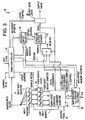
- FIGURE 3 is a schematic block diagram of an exemplary correlator 18, which can be used to implement an embodiment of the present invention.
- N adder/subtractor
- mapping logic circuitry 23 which is configured according to the codeword to produce the correct add/subtract commands to modifier 24 at different times under the control of the timing controller 20.
- the memory 21 is utilized as a circular buffer to hold M partially completed correlations.
- the next correlation to be completed is at memory location "k", where the address for "k” is maintained in an address offset register 22.
- the partial correlation at address "k” will be completed by adding an N-sample combination of N previously input samples maintained in an N-element latch 26.
- timing controller 20 outputs the just-completed correlation "k", by enabling an output gate 28 to couple the just-completed correlation "k” value to the output, and substitutes a zero value to be written to memory location "k", thus clearing the memory location "k” to zero.
- Timing controller 20 then controls selector 25 to select the latest input sample from an input shift register 27 which is to be passed to adder/subtractor 24, and at the same time controls mapping logic circuitry 23 to sequentially select memory locations k,k+1,k+2,...k+1-N to be modified by adding or subtracting the new input sample.
- Mapping logic circuitry 23 also controls the addition or subtraction for each of the N memory locations, according to a pre-stored sign pattern that depends on the codeword bits.
- mapping logic 23 When the second sample of the next four samples is input to register 27, mapping logic 23 will generate a "-" sign for memory location "k” (corresponding to the second bit of the codeword being a “1"), a "-" sign for location k+1 (corresponding to the first codeword bit being a “1"), a "+” sign for location k+2 (corresponding to the last bit of the codeword being “0”), and a "-" sign for location k+3 (corresponding to the second-to-last bit of the codeword being a "1"), and so on.
- the above-underlined bits are the first bits of the codeword that determine the signs of samples for initializing new correlations, which will be formed in the same memory locations vacated by correlations completed by using the non-underlined bits as signs (the last bits of the codeword to be correlated).
- the correlation memory location is cleared to zero between using the last non-underlined bit to complete a correlation and the first underlined bit to start a new correlation in the same location, which is performed as described above by timing controller 20 enabling output gate 28 at the appropriate times.
- Mapping logic 23 modulo-M adds the increment "i" to the base address "k” to obtain the memory address location to be updated.
- the increment "i" provided by timing controller 20 is also used by mapping logic 23 to determine the N-sample combination to be selected by selector 25, and whether the combination shall be inverted or not (by providing a "+” or "-” sign to modifier 24).
- the bracketed column of four-bit segments indicates the combination to be added to update the partial correlation of each row. If a combination is stored in selector 25 corresponding to the complement of these bit patterns, then the complementary combination is selected at the same time as a minus sign is provided to modifier 24; otherwise the correct combination (if available) is used with a "+" sign.
- the mapping of increment "i" to N-1 selection control lines input to selector 25, and a selection of +/- for modifier 24 may be accomplished, for example, by storing M-N, N-bit control signals in a memory area. When the correlation codeword was chosen or changed, then the appropriate values would be loaded into this memory area. Also, the memory area could be extended to contain the N x N sign bits needed to control formation of the starting and ending triangular fillets, which results in a total of M x N bits of memory.
- a Read-Only-Memory can be programmed with this information, and in some instances, it can be more efficient to translate the bits of the increment "i" with hard-wired logic, into the N control and selection signals to modifier 24 and selector 25. All of these possibilities, as well as the others described above, are within the scope of the present invention.
- step 1a of the sequence the previously completed correlation at the address "k" is output from the memory location, and that location is zeroed.
- step 1b the first of four new signal samples are input and added to or subtracted from memory addresses k, k+1, k+2 and k+3, as determined by the address offset register 22 which contains the address "k”. Whether to add or subtract is determined by the contents of the mapping logic 23.
- the completed correlation is output from memory location k+1, and the memory location k+1 is zeroed.
- the second signal sample is added to or subtracted from memory locations k, k+1, k+2 and k+3.
- the completed correlation is output from memory location k+2, and the memory location k+2 is zeroed.
- the third signal sample is added to or subtracted from memory locations k, k+1, k+2 and k+3.
- step 4a the completed correlation is output from memory location k+3, and the memory location k+3 is zeroed.
- the fourth signal sample is added to or subtracted from memory locations k, k+1, k+2 and k+3.
- step 4d a selected one of the combinations computed in step 4c is added to the contents of each one of the remaining memory locations k+4, k+6....k+M-1. For each such memory location, the combination selected to be added to that location is predetermined for a particular choice of codeword.
- address k is increased by 4 (modulo-M), and the sequence is repeated from step 1a.
- memory location "k" contains a combination of the four signal values with signs corresponding to the first four bits of the codeword. This combination is used as a starting point for the computation at step 4c of the other seven of the eight total combinations, which together with their respective negatives, comprise the 16 possible sign combinations of the four signal samples. One of these combinations will be needed to complete correlation k+4 by adding it to the contents of memory location k+4. In general, the order in which this value will be computed depends on the code with which the signal is being correlated, and it may be the last value to be computed.
- steps 4a through 4e are required to be completed within one sample clock period, in order to be sure to obtain in time the combination needed to complete correlation k+4 (i.e., the incremented value of k).
- the correlation so-completed is output at step 1a of the next cycle.
- steps 4e and 4d may be reversed (i.e., k can be incremented by 4 first at step 4d), but then the address k+4, k+5....k+M-1 must be expressed in terms of the new k value as k, k+1, k+2....k+M-5 for step 4e.
- step 4c requires seven operations to be completed in less than one sample clock period, but these operations can be executed in parallel with the four operations of step 4b.
- the other M-4 operations have to be completed during the remainder of the fourth sample period plus the other three operations, which is a total of M-4+7 operations that have to be accomplished within four sample clock periods. This can be accomplished by providing a computational speed of at least (M+3)/4 operations per sample clock period.
- steps 1-4d consumes an additional four arithmetic operations per sample clock period, so all of the operations can be accommodated if timing controller 20 has available a high-speed clock of at least 21 times the sample clock frequency, which allows 21 read-modify-rewrite cycles to memory 21 per sample clock period. Notably, this is a factor of three less than a prior art sliding correlator of length 64.
- memory 21 can be split into two banks, and two adder/subtractors can be provided so that two read-modify-rewrite cycles can be performed in parallel per high-speed clock period.
- the ultimate in parallelism is to split memory 21 into M/N banks of N elements, with each bank being connected to a corresponding one of M/N adder/subtractors.
- the four consecutive memory locations to be updated every new sample clock period can be stored in different banks, as can the other (M-N)/N memory locations such that all the required memory read-modify-rewrite cycles can occur in parallel.
- the 2 (N-1) combinations of N samples needed by selector 25 can be computed in Grey-code order using a chain of 2 (N-1) -1 cascaded adders, whereby an adder adds or subtracts twice a sample value to/from the output of a preceding adder to obtain all combinations in parallel with only the ripple-through delay of the logic.
- Such an arrangement has only about 1/N the hardware complexity of a prior art, fully parallel correlator that requires M-1 parallel adders.
- the method of the present invention can be used to form correlators of either longer correlation length, lower hardware complexity, higher speed, lower power consumption, or any combination of these advantages, in comparison with prior art methods.
- the improved correlator can be employed to correlate all shifts of a set of received signal samples, wherein the set does not have to be a contiguous set of signals but can be received, for example, in bursts (e.g., as in a Time Division Multiple Access (TDMA) system, or "hops" in a frequency hopping system).
- TDMA Time Division Multiple Access
- a need for the present inventive method arises, for example, whenever there is uncertainty about the timing of a received signal.
- CDMA Code Division Multiple Access
- the present correlator can be used efficiently to simultaneously despread a large plurality of RAKE taps.
- the method of the present invention can be used to compute correlations between successive shifts of M consecutive signal samples and a signal pattern of M stored sample values which are not restricted to binary values, but can include, for example, ternary values of +1,-1 and 0. All 3**N possible combinations of N signal values can be computed efficiently in a Grey-coded order, wherein only one digit at a time is changed through its allowed set of values, thus enabling a faster correlation algorithm to be devised in accordance with the inventive principles described above.
- the invention is also useful when correlations must be made with several shifts of a number of different CDMA codes, as in, for example, a navigation receiver for processing CDMA signals received from a plurality (e.g., 4 or more) Global Positioning System (GPS) satellites.
- GPS Global Positioning System
Landscapes
- Engineering & Computer Science (AREA)
- Physics & Mathematics (AREA)
- General Physics & Mathematics (AREA)
- Mathematical Optimization (AREA)
- Mathematical Physics (AREA)
- Theoretical Computer Science (AREA)
- Signal Processing (AREA)
- Mathematical Analysis (AREA)
- Computer Networks & Wireless Communication (AREA)
- Pure & Applied Mathematics (AREA)
- Computational Mathematics (AREA)
- Data Mining & Analysis (AREA)
- Algebra (AREA)
- Databases & Information Systems (AREA)
- Software Systems (AREA)
- General Engineering & Computer Science (AREA)
- Computing Systems (AREA)
- Complex Calculations (AREA)
- Synchronisation In Digital Transmission Systems (AREA)
Claims (5)
- Procédé pour produire des corrélations entre une pluralité de décalages d'un mot de code binaire incluant une première pluralité prédéterminée de bits et une pluralité correspondante d'échantillons de signal d'entrée successifs, chaque décalage de la pluralité de décalages du mot de code binaire étant décalé d'un nombre différent de positions de bit par rapport aux échantillons de signal d'entrée, le procédé comprenant les étapes consistant à :stocker une première pluralité de corrélations partiellement achevées dans un premier emplacement de stockage ;entrer une seconde pluralité desdits échantillons de signal d'entrée dans un second emplacement de stockage, ladite seconde pluralité étant inférieure à ladite première pluralité ;noter que pour une pluralité donnée de combinaisons d'échantillons possibles de la seconde pluralité desdits échantillons de signal d'entrée avec toute combinaison possible de signes plus et moins, une première moitié des combinaisons d'échantillons possibles de ladite seconde pluralité desdits échantillons de signal d'entrée avec toute combinaison possible de signes plus et moins est le négatif d'une seconde moitié des combinaisons d'échantillons possibles, et en conséquence sélectionner la première moitié des combinaisons d'échantillons possibles : et combiner les échantillons de signal d'entrée de chacune des combinaisons d'échantillons possibles de la première moitié sélectionnée pour produire une combinaison d'échantillons calculée correspondante ;sélectionner une combinaison d'échantillons à partir de la pluralité de combinaisons d'échantillons possibles, les signes plus et moins de chacun des échantillons de signal d'entrée de la combinaison d'échantillons sélectionnée correspondant à un signe de chaque bit d'une partie d'un décalage particulier de la pluralité de décalages du mot de code binaire ;si la combinaison d'échantillons sélectionnée correspond au complément d'un élément de la première moitié sélectionnée des combinaisons d'échantillons possibles, alors la combinaison complémentaire est sélectionnée, et la combinaison d'échantillons calculée correspondant à la combinaison d'échantillons sélectionnée est soustraite d'une corrélation partielle stockée particulière de ladite première pluralité de corrélations partiellement achevées correspondant au décalage particulier de la pluralité de décalages du mot de code binaire pour produire une seconde pluralité de corrélations partiellement achevées et une corrélation achevée ; etsi la combinaison d'échantillons sélectionnée correspond à un élément de la première moitié sélectionnée des combinaisons d'échantillons possibles, alors la combinaison est sélectionnée, et la combinaison d'échantillons calculée correspondant à la combinaison d'échantillons sélectionnée est ajoutée à une corrélation partielle stockée particulière de ladite première pluralité de corrélations partiellement achevées correspondant au décalage particulier de la pluralité de décalages du mot de code binaire pour produire une seconde pluralité de corrélations partiellement achevées et une corrélation achevée.
- Procédé selon la revendication 1, comprenant de plus les étapes consistant à :combiner une pluralité sélectionnée de ladite seconde pluralité desdits échantillons de signal d'entrée avec une seconde pluralité sélectionnée desdites corrélations partiellement achevées pour produire une pluralité de corrélations achevées, un nombre total de corrélations achevées étant égal à ladite seconde pluralité de corrélations partiellement achevées ;en réponse à ladite seconde pluralité desdits échantillons de signal d'entrée, créer une nouvelle première pluralité de corrélations partiellement achevées ; etrépéter les étapes précédemment mentionnées.
- Procédé selon la revendication 2, dans lequel la combinaison des échantillons de signal d'entrée de chacune des combinaisons d'échantillons possibles de la première moitié sélectionnée pour produire une combinaison d'échantillons calculée correspondante est calculée selon un ordre de code de Gray de choix de signe plus et moins.
- Procédé selon la revendication 3, dans lequel au moins une desdites combinaisons d'échantillons est calculée à partir d'une valeur précédemment calculée en ajoutant ou en soustrayant deux fois la valeur d'un échantillon de ladite seconde pluralité d'échantillons de signal d'entrée.
- Procédé selon la revendication 3, dans lequel la totalité desdites combinaisons d'échantillons suivant une première valeur calculée est dérivée à partir d'une valeur déjà calculée par l'ajout ou la soustraction de deux fois la valeur d'un échantillon de ladite seconde pluralité d'échantillons de signal d'entrée.
Applications Claiming Priority (3)
| Application Number | Priority Date | Filing Date | Title |
|---|---|---|---|
| US08/967,444 US5931893A (en) | 1997-11-11 | 1997-11-11 | Efficient correlation over a sliding window |
| US967444 | 1997-11-11 | ||
| PCT/US1998/023960 WO1999024916A1 (fr) | 1997-11-11 | 1998-11-10 | Correlation efficace sur une fenetre glissante |
Publications (2)
| Publication Number | Publication Date |
|---|---|
| EP1031098A1 EP1031098A1 (fr) | 2000-08-30 |
| EP1031098B1 true EP1031098B1 (fr) | 2006-02-08 |
Family
ID=25512804
Family Applications (1)
| Application Number | Title | Priority Date | Filing Date |
|---|---|---|---|
| EP98957780A Expired - Lifetime EP1031098B1 (fr) | 1997-11-11 | 1998-11-10 | Correlation efficace sur une fenetre glissante |
Country Status (8)
| Country | Link |
|---|---|
| US (1) | US5931893A (fr) |
| EP (1) | EP1031098B1 (fr) |
| JP (1) | JP4149665B2 (fr) |
| AU (1) | AU1395899A (fr) |
| CA (1) | CA2309681C (fr) |
| DE (1) | DE69833453T2 (fr) |
| WO (1) | WO1999024916A1 (fr) |
| ZA (1) | ZA9810119B (fr) |
Families Citing this family (77)
| Publication number | Priority date | Publication date | Assignee | Title |
|---|---|---|---|---|
| US6148313A (en) * | 1997-04-09 | 2000-11-14 | Ge Capital Spacenet Services, Inc. | Correlator method and apparatus |
| US6330292B1 (en) * | 1997-11-11 | 2001-12-11 | Telefonaktiebolaget Lm Ericsson | Reduced power matched filter |
| US5955992A (en) * | 1998-02-12 | 1999-09-21 | Shattil; Steve J. | Frequency-shifted feedback cavity used as a phased array antenna controller and carrier interference multiple access spread-spectrum transmitter |
| JP3499460B2 (ja) | 1999-02-25 | 2004-02-23 | 松下電器産業株式会社 | 拡散符号発生回路および拡散符号発生方法 |
| WO2000052862A1 (fr) * | 1999-02-26 | 2000-09-08 | Mitsubishi Denki Kabushiki Kaisha | Appareil et procede pour demodulation cdma et systeme de communication pour mobiles cdma |
| US6038271A (en) * | 1999-03-02 | 2000-03-14 | Harris Corporation | Correlator with cascade data paths to facilitate expansion of correlator length |
| JP2000307477A (ja) * | 1999-04-21 | 2000-11-02 | Matsushita Electric Ind Co Ltd | 符号発生装置、その装置を用いた通信装置、通信システム及び符号発生方法 |
| US6606346B2 (en) * | 2001-05-18 | 2003-08-12 | Global Locate, Inc. | Method and apparatus for computing signal correlation |
| US9020756B2 (en) * | 1999-04-23 | 2015-04-28 | Global Locate, Inc. | Method and apparatus for processing satellite positioning system signals |
| US6704348B2 (en) * | 2001-05-18 | 2004-03-09 | Global Locate, Inc. | Method and apparatus for computing signal correlation at multiple resolutions |
| KR100450789B1 (ko) | 1999-05-25 | 2004-10-01 | 삼성전자주식회사 | 유사 잡음 코드 획득 장치 및 이를 구비한 직접 시퀀스 코드분할 다중 접속 수신기 |
| GB2357406B (en) * | 1999-12-14 | 2004-01-21 | Nokia Mobile Phones Ltd | Combiner |
| JP4313917B2 (ja) * | 2000-01-05 | 2009-08-12 | キヤノン株式会社 | 復調装置 |
| JP2001244850A (ja) * | 2000-03-02 | 2001-09-07 | Kawasaki Steel Corp | スライディング相関器 |
| US6934317B1 (en) | 2000-10-11 | 2005-08-23 | Ericsson Inc. | Systems and methods for communicating spread spectrum signals using variable signal constellations |
| US8670390B2 (en) | 2000-11-22 | 2014-03-11 | Genghiscomm Holdings, LLC | Cooperative beam-forming in wireless networks |
| US10355720B2 (en) | 2001-04-26 | 2019-07-16 | Genghiscomm Holdings, LLC | Distributed software-defined radio |
| US10931338B2 (en) | 2001-04-26 | 2021-02-23 | Genghiscomm Holdings, LLC | Coordinated multipoint systems |
| US9819449B2 (en) | 2002-05-14 | 2017-11-14 | Genghiscomm Holdings, LLC | Cooperative subspace demultiplexing in content delivery networks |
| US7769076B2 (en) | 2001-05-18 | 2010-08-03 | Broadcom Corporation | Method and apparatus for performing frequency synchronization |
| US7190712B2 (en) * | 2001-05-18 | 2007-03-13 | Global Locate, Inc | Method and apparatus for performing signal correlation |
| US7006556B2 (en) | 2001-05-18 | 2006-02-28 | Global Locate, Inc. | Method and apparatus for performing signal correlation at multiple resolutions to mitigate multipath interference |
| US7995682B2 (en) * | 2001-05-18 | 2011-08-09 | Broadcom Corporation | Method and apparatus for performing signal processing using historical correlation data |
| US7567636B2 (en) * | 2001-05-18 | 2009-07-28 | Global Locate, Inc. | Method and apparatus for performing signal correlation using historical correlation data |
| US8098716B2 (en) * | 2001-05-18 | 2012-01-17 | Broadcom Corporation | Method and apparatus for providing an energy-based signal tracking loop |
| US10200227B2 (en) | 2002-05-14 | 2019-02-05 | Genghiscomm Holdings, LLC | Pre-coding in multi-user MIMO |
| US10142082B1 (en) | 2002-05-14 | 2018-11-27 | Genghiscomm Holdings, LLC | Pre-coding in OFDM |
| US9628231B2 (en) | 2002-05-14 | 2017-04-18 | Genghiscomm Holdings, LLC | Spreading and precoding in OFDM |
| US10644916B1 (en) | 2002-05-14 | 2020-05-05 | Genghiscomm Holdings, LLC | Spreading and precoding in OFDM |
| RU2227321C2 (ru) * | 2002-07-17 | 2004-04-20 | Аванесян Гарри Романович | Корреляционный анализатор |
| RU2229157C2 (ru) * | 2002-09-03 | 2004-05-20 | Аванесян Гарри Романович | Корреляционный измеритель временных сдвигов |
| WO2005002120A2 (fr) * | 2003-06-12 | 2005-01-06 | California Institute Of Technology | Procede et appareil de regulation de l'encombrement d'un reseau |
| JP2006041694A (ja) * | 2004-07-23 | 2006-02-09 | Japan Radio Co Ltd | スペクトラム拡散信号受信装置 |
| US11184037B1 (en) | 2004-08-02 | 2021-11-23 | Genghiscomm Holdings, LLC | Demodulating and decoding carrier interferometry signals |
| US11381285B1 (en) | 2004-08-02 | 2022-07-05 | Genghiscomm Holdings, LLC | Transmit pre-coding |
| US11552737B1 (en) | 2004-08-02 | 2023-01-10 | Genghiscomm Holdings, LLC | Cooperative MIMO |
| US7512172B2 (en) * | 2004-09-30 | 2009-03-31 | Yan Zhang | Path search method for CDMA communication systems |
| CN101151813B (zh) * | 2005-01-31 | 2012-04-25 | Nxp股份有限公司 | 用于实现无线通信系统中的匹配滤波器的方法和设备 |
| US20060185836A1 (en) * | 2005-02-24 | 2006-08-24 | Scott Garner | Thermally coupled surfaces having controlled minimum clearance |
| US8107443B2 (en) * | 2009-02-10 | 2012-01-31 | Mediatek Inc. | Method of performing cell search for a wireless communications system |
| IT1396405B1 (it) * | 2009-10-28 | 2012-11-19 | St Microelectronics Srl | Procedimento e dispositivo per l'acquisizione di segnali satellitari, corrispondente prodotto informatico. |
| US20110285382A1 (en) * | 2010-05-18 | 2011-11-24 | General Electric Company | Power meter phase identification |
| JP6060483B2 (ja) * | 2012-01-11 | 2017-01-18 | セイコーエプソン株式会社 | 衛星信号捕捉方法及び衛星信号捕捉装置 |
| RU2500025C2 (ru) * | 2012-07-20 | 2013-11-27 | Гарри Романович Аванесян | Корреляционный измеритель временных сдвигов случайных сигналов |
| US9130786B2 (en) * | 2013-03-15 | 2015-09-08 | Qualcomm Incorporated | Device and method for computing a channel estimate |
| US12224860B1 (en) | 2014-01-30 | 2025-02-11 | Genghiscomm Holdings, LLC | Linear coding in decentralized networks |
| JP6324264B2 (ja) * | 2014-08-22 | 2018-05-16 | ルネサスエレクトロニクス株式会社 | 三値内積演算回路、三値内積演算処理プログラム、及び、三値内積演算回路による演算処理方法 |
| WO2017175190A1 (fr) | 2016-04-07 | 2017-10-12 | Uhnder, Inc. | Transmission adaptative et annulation de brouillage pour radar mimo |
| US10261179B2 (en) | 2016-04-07 | 2019-04-16 | Uhnder, Inc. | Software defined automotive radar |
| US9846228B2 (en) | 2016-04-07 | 2017-12-19 | Uhnder, Inc. | Software defined automotive radar systems |
| US9791551B1 (en) | 2016-04-25 | 2017-10-17 | Uhnder, Inc. | Vehicular radar system with self-interference cancellation |
| WO2017187306A1 (fr) | 2016-04-25 | 2017-11-02 | Uhnder, Inc. | Filtrage adaptatif pour atténuation d'interférence fmcw dans des systèmes de radar pmcw |
| US10573959B2 (en) | 2016-04-25 | 2020-02-25 | Uhnder, Inc. | Vehicle radar system using shaped antenna patterns |
| EP3449272B1 (fr) | 2016-04-25 | 2022-11-02 | Uhnder, Inc. | Système radar de véhicule comportant un système radar et de communication partagé, et procédé de gestion d'un tel système au sein d'un véhicule |
| US9945935B2 (en) | 2016-04-25 | 2018-04-17 | Uhnder, Inc. | Digital frequency modulated continuous wave radar using handcrafted constant envelope modulation |
| US9806914B1 (en) | 2016-04-25 | 2017-10-31 | Uhnder, Inc. | Successive signal interference mitigation |
| WO2017187242A1 (fr) | 2016-04-25 | 2017-11-02 | Uhnder, Inc. | Micro-doppler à balayage multiple à la demande pour véhicule |
| US9575160B1 (en) | 2016-04-25 | 2017-02-21 | Uhnder, Inc. | Vehicular radar sensing system utilizing high rate true random number generator |
| EP3449275B1 (fr) | 2016-04-25 | 2025-08-20 | Robert Bosch GmbH | Atténuation d'interférences pmcw-pmcw |
| US9753121B1 (en) | 2016-06-20 | 2017-09-05 | Uhnder, Inc. | Power control for improved near-far performance of radar systems |
| US9869762B1 (en) | 2016-09-16 | 2018-01-16 | Uhnder, Inc. | Virtual radar configuration for 2D array |
| WO2018146530A1 (fr) | 2017-02-10 | 2018-08-16 | Uhnder, Inc. | Corrélation basée sur une fft à complexité réduite pour un radar automobile |
| US11454697B2 (en) | 2017-02-10 | 2022-09-27 | Uhnder, Inc. | Increasing performance of a receive pipeline of a radar with memory optimization |
| US9971020B1 (en) | 2017-02-10 | 2018-05-15 | Uhnder, Inc. | Radar data buffering |
| US10637705B1 (en) | 2017-05-25 | 2020-04-28 | Genghiscomm Holdings, LLC | Peak-to-average-power reduction for OFDM multiple access |
| US10243773B1 (en) | 2017-06-30 | 2019-03-26 | Genghiscomm Holdings, LLC | Efficient peak-to-average-power reduction for OFDM and MIMO-OFDM |
| US11105890B2 (en) | 2017-12-14 | 2021-08-31 | Uhnder, Inc. | Frequency modulated signal cancellation in variable power mode for radar applications |
| US12386029B2 (en) | 2018-01-29 | 2025-08-12 | Robert Bosch Gmbh | Millimeter wave automotive radar systems |
| US11917604B2 (en) | 2019-01-25 | 2024-02-27 | Tybalt, Llc | Orthogonal multiple access and non-orthogonal multiple access |
| US11343823B2 (en) | 2020-08-16 | 2022-05-24 | Tybalt, Llc | Orthogonal multiple access and non-orthogonal multiple access |
| US12206535B1 (en) | 2018-06-17 | 2025-01-21 | Tybalt, Llc | Artificial neural networks in wireless communication systems |
| US11474225B2 (en) | 2018-11-09 | 2022-10-18 | Uhnder, Inc. | Pulse digital mimo radar system |
| CN113454964A (zh) | 2019-01-25 | 2021-09-28 | 珍吉斯科姆控股有限责任公司 | 正交多址和非正交多址 |
| US11681017B2 (en) | 2019-03-12 | 2023-06-20 | Uhnder, Inc. | Method and apparatus for mitigation of low frequency noise in radar systems |
| WO2020242898A1 (fr) | 2019-05-26 | 2020-12-03 | Genghiscomm Holdings, LLC | Accès multiple non orthogonal |
| WO2021144710A2 (fr) | 2020-01-13 | 2021-07-22 | Uhnder, Inc. | Procédé et système pour le fonctionnement multi-puce de systèmes radar |
| US12498452B2 (en) | 2021-12-02 | 2025-12-16 | Robert Bosch Gmbh | Radar system with enhanced processing for increased contrast ratio, improved angular separability and accuracy, and elimination of ghost targets in a single-snapshot |
Family Cites Families (6)
| Publication number | Priority date | Publication date | Assignee | Title |
|---|---|---|---|---|
| US4071903A (en) * | 1976-08-04 | 1978-01-31 | International Business Machines Corporation | Autocorrelation function factor generating method and circuitry therefor |
| US5579338A (en) * | 1992-06-29 | 1996-11-26 | Mitsubishi Denki Kabushiki Kaisha | Spread spectrum receiver using partial correlations |
| US5365549A (en) * | 1993-05-24 | 1994-11-15 | Motorola, Inc. | Complex signal correlator and method therefor |
| US5790606A (en) * | 1994-01-11 | 1998-08-04 | Ericsson Inc. | Joint demodulation using spatial maximum likelihood |
| CN1068163C (zh) * | 1994-04-22 | 2001-07-04 | Ntt移动通信网株式会社 | 码分多路复用信号接收方法 |
| US5684727A (en) * | 1996-02-07 | 1997-11-04 | Macdonald, Dettwiler And Associates Ltd. | High-speed correlator |
-
1997
- 1997-11-11 US US08/967,444 patent/US5931893A/en not_active Expired - Lifetime
-
1998
- 1998-11-05 ZA ZA9810119A patent/ZA9810119B/xx unknown
- 1998-11-10 JP JP2000519843A patent/JP4149665B2/ja not_active Expired - Lifetime
- 1998-11-10 EP EP98957780A patent/EP1031098B1/fr not_active Expired - Lifetime
- 1998-11-10 WO PCT/US1998/023960 patent/WO1999024916A1/fr not_active Ceased
- 1998-11-10 DE DE69833453T patent/DE69833453T2/de not_active Expired - Lifetime
- 1998-11-10 CA CA002309681A patent/CA2309681C/fr not_active Expired - Fee Related
- 1998-11-10 AU AU13958/99A patent/AU1395899A/en not_active Abandoned
Also Published As
| Publication number | Publication date |
|---|---|
| ZA9810119B (en) | 1999-05-07 |
| WO1999024916A1 (fr) | 1999-05-20 |
| AU1395899A (en) | 1999-05-31 |
| CA2309681A1 (fr) | 1999-05-20 |
| CA2309681C (fr) | 2007-06-26 |
| JP2001523055A (ja) | 2001-11-20 |
| DE69833453T2 (de) | 2006-09-28 |
| DE69833453D1 (de) | 2006-04-20 |
| JP4149665B2 (ja) | 2008-09-10 |
| US5931893A (en) | 1999-08-03 |
| EP1031098A1 (fr) | 2000-08-30 |
Similar Documents
| Publication | Publication Date | Title |
|---|---|---|
| US5931893A (en) | Efficient correlation over a sliding window | |
| US6330292B1 (en) | Reduced power matched filter | |
| US6339781B1 (en) | M-sequence generator and PN code generator with mask table for obtaining arbitrary phase shift | |
| EP1102408B1 (fr) | Décodeur Viterbi | |
| EP1192714B1 (fr) | Filtre adapte mettant en application un calcul prealable pour limiter la consommation de puissance | |
| US5323402A (en) | Programmable systolic BCH decoder | |
| US4567594A (en) | Reed-Solomon error detecting and correcting system employing pipelined processors | |
| JP4369019B2 (ja) | 擬似雑音コード獲得装置及びこれを具備した直接シーケンスコード分割多重接続受信器 | |
| US7917835B2 (en) | Memory system and method for use in trellis-based decoding | |
| EP1195007A1 (fr) | Filtres de correspondance utilisant des combinaisons preetablies formees par multiplexage de duree | |
| KR20050083747A (ko) | 컴팩트 갈루아 필드 곱셈기 엔진 | |
| KR101017530B1 (ko) | 인터리브된 어드레스를 발생시키는 방법 및 장치 | |
| EP2827516B1 (fr) | Procédé et appareil de génération de code de brouillage, et appareil de traitement de code de brouillage | |
| US4754422A (en) | Dividing apparatus | |
| JPH09305572A (ja) | ガロア体の除算方法および除算装置 | |
| US6145113A (en) | Series reed-solomon decoder synchronized with bit clock signal | |
| US5099483A (en) | Device for correcting errors by a long-distance code | |
| US5862159A (en) | Parallelized cyclical redundancy check method | |
| KR100377415B1 (ko) | 고속 디지털 정합 필터 장치 | |
| KR100456494B1 (ko) | 수신기 및 역확산 부호 생성 방법 | |
| JPH09162753A (ja) | 符号語の復号方式 | |
| JPH1011268A (ja) | 擬似ランダム系列符号発生装置 | |
| KR970002735B1 (ko) | 의사난수 매스크 생성기를 이용한 의사난수 발생장치 | |
| JP2710626B2 (ja) | ブロック同期回路 | |
| JP2005117265A (ja) | パスサーチ回路、パスサーチ方法 |
Legal Events
| Date | Code | Title | Description |
|---|---|---|---|
| PUAI | Public reference made under article 153(3) epc to a published international application that has entered the european phase |
Free format text: ORIGINAL CODE: 0009012 |
|
| 17P | Request for examination filed |
Effective date: 20000502 |
|
| AK | Designated contracting states |
Kind code of ref document: A1 Designated state(s): DE GB |
|
| 17Q | First examination report despatched |
Effective date: 20020218 |
|
| RAP1 | Party data changed (applicant data changed or rights of an application transferred) |
Owner name: ERICSSON INC. |
|
| GRAP | Despatch of communication of intention to grant a patent |
Free format text: ORIGINAL CODE: EPIDOSNIGR1 |
|
| GRAS | Grant fee paid |
Free format text: ORIGINAL CODE: EPIDOSNIGR3 |
|
| GRAA | (expected) grant |
Free format text: ORIGINAL CODE: 0009210 |
|
| AK | Designated contracting states |
Kind code of ref document: B1 Designated state(s): DE GB |
|
| REG | Reference to a national code |
Ref country code: GB Ref legal event code: FG4D |
|
| REF | Corresponds to: |
Ref document number: 69833453 Country of ref document: DE Date of ref document: 20060420 Kind code of ref document: P |
|
| PLBE | No opposition filed within time limit |
Free format text: ORIGINAL CODE: 0009261 |
|
| STAA | Information on the status of an ep patent application or granted ep patent |
Free format text: STATUS: NO OPPOSITION FILED WITHIN TIME LIMIT |
|
| 26N | No opposition filed |
Effective date: 20061109 |
|
| PGFP | Annual fee paid to national office [announced via postgrant information from national office to epo] |
Ref country code: DE Payment date: 20131127 Year of fee payment: 16 Ref country code: GB Payment date: 20131127 Year of fee payment: 16 |
|
| REG | Reference to a national code |
Ref country code: DE Ref legal event code: R119 Ref document number: 69833453 Country of ref document: DE |
|
| GBPC | Gb: european patent ceased through non-payment of renewal fee |
Effective date: 20141110 |
|
| PG25 | Lapsed in a contracting state [announced via postgrant information from national office to epo] |
Ref country code: GB Free format text: LAPSE BECAUSE OF NON-PAYMENT OF DUE FEES Effective date: 20141110 Ref country code: DE Free format text: LAPSE BECAUSE OF NON-PAYMENT OF DUE FEES Effective date: 20150602 |