EP1031403A1 - Procédé de fabrication d'une préforme - Google Patents
Procédé de fabrication d'une préforme Download PDFInfo
- Publication number
- EP1031403A1 EP1031403A1 EP20000301407 EP00301407A EP1031403A1 EP 1031403 A1 EP1031403 A1 EP 1031403A1 EP 20000301407 EP20000301407 EP 20000301407 EP 00301407 A EP00301407 A EP 00301407A EP 1031403 A1 EP1031403 A1 EP 1031403A1
- Authority
- EP
- European Patent Office
- Prior art keywords
- preform
- positioning
- blank
- outline
- waste plastic
- Prior art date
- Legal status (The legal status is an assumption and is not a legal conclusion. Google has not performed a legal analysis and makes no representation as to the accuracy of the status listed.)
- Granted
Links
- 238000000034 method Methods 0.000 title claims abstract description 56
- 239000000463 material Substances 0.000 claims abstract description 122
- 229920003023 plastic Polymers 0.000 claims abstract description 77
- 239000004033 plastic Substances 0.000 claims abstract description 76
- 239000002699 waste material Substances 0.000 claims abstract description 63
- 239000012779 reinforcing material Substances 0.000 claims abstract description 20
- 238000004519 manufacturing process Methods 0.000 claims abstract description 11
- 239000011347 resin Substances 0.000 claims description 38
- 229920005989 resin Polymers 0.000 claims description 38
- 238000000151 deposition Methods 0.000 claims description 36
- 239000000835 fiber Substances 0.000 claims description 19
- 239000002985 plastic film Substances 0.000 claims description 16
- 229920006255 plastic film Polymers 0.000 claims description 13
- 238000010438 heat treatment Methods 0.000 claims description 12
- 230000003014 reinforcing effect Effects 0.000 claims description 12
- 230000000063 preceeding effect Effects 0.000 claims 7
- 239000012783 reinforcing fiber Substances 0.000 description 11
- 238000000465 moulding Methods 0.000 description 8
- 238000000748 compression moulding Methods 0.000 description 6
- 238000007596 consolidation process Methods 0.000 description 6
- 244000198134 Agave sisalana Species 0.000 description 4
- 240000000491 Corchorus aestuans Species 0.000 description 4
- 235000011777 Corchorus aestuans Nutrition 0.000 description 4
- 235000010862 Corchorus capsularis Nutrition 0.000 description 4
- 240000000797 Hibiscus cannabinus Species 0.000 description 4
- 241000208202 Linaceae Species 0.000 description 4
- 235000004431 Linum usitatissimum Nutrition 0.000 description 4
- 238000005520 cutting process Methods 0.000 description 4
- 239000002657 fibrous material Substances 0.000 description 4
- 239000010817 post-consumer waste Substances 0.000 description 4
- 230000006835 compression Effects 0.000 description 3
- 238000007906 compression Methods 0.000 description 3
- 239000011521 glass Substances 0.000 description 3
- 239000002440 industrial waste Substances 0.000 description 3
- 239000000203 mixture Substances 0.000 description 3
- 239000002245 particle Substances 0.000 description 3
- -1 polypropylene Polymers 0.000 description 3
- 238000005728 strengthening Methods 0.000 description 3
- 239000012209 synthetic fiber Substances 0.000 description 3
- 229920002994 synthetic fiber Polymers 0.000 description 3
- 239000004743 Polypropylene Substances 0.000 description 2
- 239000011324 bead Substances 0.000 description 2
- 239000008187 granular material Substances 0.000 description 2
- 239000012535 impurity Substances 0.000 description 2
- 235000019645 odor Nutrition 0.000 description 2
- 239000008188 pellet Substances 0.000 description 2
- 229920001155 polypropylene Polymers 0.000 description 2
- 239000012815 thermoplastic material Substances 0.000 description 2
- 238000009966 trimming Methods 0.000 description 2
- 229910000831 Steel Inorganic materials 0.000 description 1
- 239000011230 binding agent Substances 0.000 description 1
- 238000000071 blow moulding Methods 0.000 description 1
- 239000003153 chemical reaction reagent Substances 0.000 description 1
- 239000010791 domestic waste Substances 0.000 description 1
- 229920001971 elastomer Polymers 0.000 description 1
- 239000004744 fabric Substances 0.000 description 1
- 239000012530 fluid Substances 0.000 description 1
- 239000006260 foam Substances 0.000 description 1
- 239000010985 leather Substances 0.000 description 1
- 239000002184 metal Substances 0.000 description 1
- 229910052751 metal Inorganic materials 0.000 description 1
- 150000002739 metals Chemical class 0.000 description 1
- 239000000123 paper Substances 0.000 description 1
- 229920000139 polyethylene terephthalate Polymers 0.000 description 1
- 239000005020 polyethylene terephthalate Substances 0.000 description 1
- 239000002994 raw material Substances 0.000 description 1
- 238000011084 recovery Methods 0.000 description 1
- 238000004064 recycling Methods 0.000 description 1
- 230000001105 regulatory effect Effects 0.000 description 1
- 239000005060 rubber Substances 0.000 description 1
- 238000007493 shaping process Methods 0.000 description 1
- 239000010959 steel Substances 0.000 description 1
- 229920002397 thermoplastic olefin Polymers 0.000 description 1
- 229920001187 thermosetting polymer Polymers 0.000 description 1
- 125000000391 vinyl group Chemical group [H]C([*])=C([H])[H] 0.000 description 1
- 229920002554 vinyl polymer Polymers 0.000 description 1
- XLYOFNOQVPJJNP-UHFFFAOYSA-N water Substances O XLYOFNOQVPJJNP-UHFFFAOYSA-N 0.000 description 1
Images


Classifications
-
- B—PERFORMING OPERATIONS; TRANSPORTING
- B29—WORKING OF PLASTICS; WORKING OF SUBSTANCES IN A PLASTIC STATE IN GENERAL
- B29B—PREPARATION OR PRETREATMENT OF THE MATERIAL TO BE SHAPED; MAKING GRANULES OR PREFORMS; RECOVERY OF PLASTICS OR OTHER CONSTITUENTS OF WASTE MATERIAL CONTAINING PLASTICS
- B29B11/00—Making preforms
- B29B11/06—Making preforms by moulding the material
- B29B11/12—Compression moulding
-
- B—PERFORMING OPERATIONS; TRANSPORTING
- B29—WORKING OF PLASTICS; WORKING OF SUBSTANCES IN A PLASTIC STATE IN GENERAL
- B29B—PREPARATION OR PRETREATMENT OF THE MATERIAL TO BE SHAPED; MAKING GRANULES OR PREFORMS; RECOVERY OF PLASTICS OR OTHER CONSTITUENTS OF WASTE MATERIAL CONTAINING PLASTICS
- B29B11/00—Making preforms
- B29B11/14—Making preforms characterised by structure or composition
- B29B11/16—Making preforms characterised by structure or composition comprising fillers or reinforcement
-
- B—PERFORMING OPERATIONS; TRANSPORTING
- B29—WORKING OF PLASTICS; WORKING OF SUBSTANCES IN A PLASTIC STATE IN GENERAL
- B29B—PREPARATION OR PRETREATMENT OF THE MATERIAL TO BE SHAPED; MAKING GRANULES OR PREFORMS; RECOVERY OF PLASTICS OR OTHER CONSTITUENTS OF WASTE MATERIAL CONTAINING PLASTICS
- B29B17/00—Recovery of plastics or other constituents of waste material containing plastics
- B29B17/0026—Recovery of plastics or other constituents of waste material containing plastics by agglomeration or compacting
- B29B17/0042—Recovery of plastics or other constituents of waste material containing plastics by agglomeration or compacting for shaping parts, e.g. multilayered parts with at least one layer containing regenerated plastic
-
- B—PERFORMING OPERATIONS; TRANSPORTING
- B29—WORKING OF PLASTICS; WORKING OF SUBSTANCES IN A PLASTIC STATE IN GENERAL
- B29C—SHAPING OR JOINING OF PLASTICS; SHAPING OF MATERIAL IN A PLASTIC STATE, NOT OTHERWISE PROVIDED FOR; AFTER-TREATMENT OF THE SHAPED PRODUCTS, e.g. REPAIRING
- B29C31/00—Handling, e.g. feeding of the material to be shaped, storage of plastics material before moulding; Automation, i.e. automated handling lines in plastics processing plants, e.g. using manipulators or robots
- B29C31/04—Feeding of the material to be moulded, e.g. into a mould cavity
- B29C31/042—Feeding of the material to be moulded, e.g. into a mould cavity using dispensing heads, e.g. extruders, placed over or apart from the moulds
-
- B—PERFORMING OPERATIONS; TRANSPORTING
- B29—WORKING OF PLASTICS; WORKING OF SUBSTANCES IN A PLASTIC STATE IN GENERAL
- B29C—SHAPING OR JOINING OF PLASTICS; SHAPING OF MATERIAL IN A PLASTIC STATE, NOT OTHERWISE PROVIDED FOR; AFTER-TREATMENT OF THE SHAPED PRODUCTS, e.g. REPAIRING
- B29C43/00—Compression moulding, i.e. applying external pressure to flow the moulding material; Apparatus therefor
- B29C43/02—Compression moulding, i.e. applying external pressure to flow the moulding material; Apparatus therefor of articles of definite length, i.e. discrete articles
- B29C43/14—Compression moulding, i.e. applying external pressure to flow the moulding material; Apparatus therefor of articles of definite length, i.e. discrete articles in several steps
-
- B—PERFORMING OPERATIONS; TRANSPORTING
- B29—WORKING OF PLASTICS; WORKING OF SUBSTANCES IN A PLASTIC STATE IN GENERAL
- B29C—SHAPING OR JOINING OF PLASTICS; SHAPING OF MATERIAL IN A PLASTIC STATE, NOT OTHERWISE PROVIDED FOR; AFTER-TREATMENT OF THE SHAPED PRODUCTS, e.g. REPAIRING
- B29C43/00—Compression moulding, i.e. applying external pressure to flow the moulding material; Apparatus therefor
- B29C43/02—Compression moulding, i.e. applying external pressure to flow the moulding material; Apparatus therefor of articles of definite length, i.e. discrete articles
- B29C43/18—Compression moulding, i.e. applying external pressure to flow the moulding material; Apparatus therefor of articles of definite length, i.e. discrete articles incorporating preformed parts or layers, e.g. compression moulding around inserts or for coating articles
- B29C43/183—Compression moulding, i.e. applying external pressure to flow the moulding material; Apparatus therefor of articles of definite length, i.e. discrete articles incorporating preformed parts or layers, e.g. compression moulding around inserts or for coating articles the preformed layer being a lining, e.g. shaped in the mould before compression moulding, or a preformed shell adapted to the shape of the mould
-
- B—PERFORMING OPERATIONS; TRANSPORTING
- B29—WORKING OF PLASTICS; WORKING OF SUBSTANCES IN A PLASTIC STATE IN GENERAL
- B29C—SHAPING OR JOINING OF PLASTICS; SHAPING OF MATERIAL IN A PLASTIC STATE, NOT OTHERWISE PROVIDED FOR; AFTER-TREATMENT OF THE SHAPED PRODUCTS, e.g. REPAIRING
- B29C43/00—Compression moulding, i.e. applying external pressure to flow the moulding material; Apparatus therefor
- B29C43/32—Component parts, details or accessories; Auxiliary operations
- B29C43/34—Feeding the material to the mould or the compression means
-
- B—PERFORMING OPERATIONS; TRANSPORTING
- B29—WORKING OF PLASTICS; WORKING OF SUBSTANCES IN A PLASTIC STATE IN GENERAL
- B29K—INDEXING SCHEME ASSOCIATED WITH SUBCLASSES B29B, B29C OR B29D, RELATING TO MOULDING MATERIALS OR TO MATERIALS FOR MOULDS, REINFORCEMENTS, FILLERS OR PREFORMED PARTS, e.g. INSERTS
- B29K2105/00—Condition, form or state of moulded material or of the material to be shaped
- B29K2105/06—Condition, form or state of moulded material or of the material to be shaped containing reinforcements, fillers or inserts
- B29K2105/08—Condition, form or state of moulded material or of the material to be shaped containing reinforcements, fillers or inserts of continuous length, e.g. cords, rovings, mats, fabrics, strands or yarns
-
- B—PERFORMING OPERATIONS; TRANSPORTING
- B29—WORKING OF PLASTICS; WORKING OF SUBSTANCES IN A PLASTIC STATE IN GENERAL
- B29K—INDEXING SCHEME ASSOCIATED WITH SUBCLASSES B29B, B29C OR B29D, RELATING TO MOULDING MATERIALS OR TO MATERIALS FOR MOULDS, REINFORCEMENTS, FILLERS OR PREFORMED PARTS, e.g. INSERTS
- B29K2105/00—Condition, form or state of moulded material or of the material to be shaped
- B29K2105/06—Condition, form or state of moulded material or of the material to be shaped containing reinforcements, fillers or inserts
- B29K2105/12—Condition, form or state of moulded material or of the material to be shaped containing reinforcements, fillers or inserts of short lengths, e.g. chopped filaments, staple fibres or bristles
-
- B—PERFORMING OPERATIONS; TRANSPORTING
- B29—WORKING OF PLASTICS; WORKING OF SUBSTANCES IN A PLASTIC STATE IN GENERAL
- B29K—INDEXING SCHEME ASSOCIATED WITH SUBCLASSES B29B, B29C OR B29D, RELATING TO MOULDING MATERIALS OR TO MATERIALS FOR MOULDS, REINFORCEMENTS, FILLERS OR PREFORMED PARTS, e.g. INSERTS
- B29K2105/00—Condition, form or state of moulded material or of the material to be shaped
- B29K2105/25—Solid
- B29K2105/251—Particles, powder or granules
-
- B—PERFORMING OPERATIONS; TRANSPORTING
- B29—WORKING OF PLASTICS; WORKING OF SUBSTANCES IN A PLASTIC STATE IN GENERAL
- B29K—INDEXING SCHEME ASSOCIATED WITH SUBCLASSES B29B, B29C OR B29D, RELATING TO MOULDING MATERIALS OR TO MATERIALS FOR MOULDS, REINFORCEMENTS, FILLERS OR PREFORMED PARTS, e.g. INSERTS
- B29K2105/00—Condition, form or state of moulded material or of the material to be shaped
- B29K2105/25—Solid
- B29K2105/253—Preform
- B29K2105/256—Sheets, plates, blanks or films
-
- B—PERFORMING OPERATIONS; TRANSPORTING
- B29—WORKING OF PLASTICS; WORKING OF SUBSTANCES IN A PLASTIC STATE IN GENERAL
- B29K—INDEXING SCHEME ASSOCIATED WITH SUBCLASSES B29B, B29C OR B29D, RELATING TO MOULDING MATERIALS OR TO MATERIALS FOR MOULDS, REINFORCEMENTS, FILLERS OR PREFORMED PARTS, e.g. INSERTS
- B29K2105/00—Condition, form or state of moulded material or of the material to be shaped
- B29K2105/26—Scrap or recycled material
-
- B—PERFORMING OPERATIONS; TRANSPORTING
- B29—WORKING OF PLASTICS; WORKING OF SUBSTANCES IN A PLASTIC STATE IN GENERAL
- B29K—INDEXING SCHEME ASSOCIATED WITH SUBCLASSES B29B, B29C OR B29D, RELATING TO MOULDING MATERIALS OR TO MATERIALS FOR MOULDS, REINFORCEMENTS, FILLERS OR PREFORMED PARTS, e.g. INSERTS
- B29K2995/00—Properties of moulding materials, reinforcements, fillers, preformed parts or moulds
- B29K2995/0018—Properties of moulding materials, reinforcements, fillers, preformed parts or moulds having particular optical properties, e.g. fluorescent or phosphorescent
- B29K2995/002—Coloured
- B29K2995/0021—Multi-coloured
-
- B—PERFORMING OPERATIONS; TRANSPORTING
- B29—WORKING OF PLASTICS; WORKING OF SUBSTANCES IN A PLASTIC STATE IN GENERAL
- B29L—INDEXING SCHEME ASSOCIATED WITH SUBCLASS B29C, RELATING TO PARTICULAR ARTICLES
- B29L2031/00—Other particular articles
- B29L2031/30—Vehicles, e.g. ships or aircraft, or body parts thereof
- B29L2031/3005—Body finishings
- B29L2031/3014—Door linings
-
- B—PERFORMING OPERATIONS; TRANSPORTING
- B29—WORKING OF PLASTICS; WORKING OF SUBSTANCES IN A PLASTIC STATE IN GENERAL
- B29L—INDEXING SCHEME ASSOCIATED WITH SUBCLASS B29C, RELATING TO PARTICULAR ARTICLES
- B29L2031/00—Other particular articles
- B29L2031/30—Vehicles, e.g. ships or aircraft, or body parts thereof
- B29L2031/3005—Body finishings
- B29L2031/3041—Trim panels
-
- Y—GENERAL TAGGING OF NEW TECHNOLOGICAL DEVELOPMENTS; GENERAL TAGGING OF CROSS-SECTIONAL TECHNOLOGIES SPANNING OVER SEVERAL SECTIONS OF THE IPC; TECHNICAL SUBJECTS COVERED BY FORMER USPC CROSS-REFERENCE ART COLLECTIONS [XRACs] AND DIGESTS
- Y02—TECHNOLOGIES OR APPLICATIONS FOR MITIGATION OR ADAPTATION AGAINST CLIMATE CHANGE
- Y02W—CLIMATE CHANGE MITIGATION TECHNOLOGIES RELATED TO WASTEWATER TREATMENT OR WASTE MANAGEMENT
- Y02W30/00—Technologies for solid waste management
- Y02W30/50—Reuse, recycling or recovery technologies
- Y02W30/62—Plastics recycling; Rubber recycling
-
- Y—GENERAL TAGGING OF NEW TECHNOLOGICAL DEVELOPMENTS; GENERAL TAGGING OF CROSS-SECTIONAL TECHNOLOGIES SPANNING OVER SEVERAL SECTIONS OF THE IPC; TECHNICAL SUBJECTS COVERED BY FORMER USPC CROSS-REFERENCE ART COLLECTIONS [XRACs] AND DIGESTS
- Y10—TECHNICAL SUBJECTS COVERED BY FORMER USPC
- Y10S—TECHNICAL SUBJECTS COVERED BY FORMER USPC CROSS-REFERENCE ART COLLECTIONS [XRACs] AND DIGESTS
- Y10S264/00—Plastic and nonmetallic article shaping or treating: processes
- Y10S264/911—Recycling consumer used articles or products
Definitions
- the invention relates to a method of forming a preform using waste plastic material.
- a prior method of forming a plastic preform includes extruding virgin resin to form a flat plastic sheet, and die-cutting the plastic sheet to form the preform. Because the preform is made entirely of virgin resin, the preform is relatively costly to manufacture. Furthermore, because the plastic sheet is die-cut to obtain the desired shape of the preform, there is significant excess or scrap material associated with this method. The preform must also be heated prior to and/or during a subsequent molding operation.
- Another method of forming a preform includes die-cutting layers of fibrous material from rectangular blanks or continuous rolls of material.
- the fibrous layers which may include synthetic fibers and/or natural fibers impregnated with resin, are then heated and compressed together to form the preform. Because the fibrous layers are die-cut to obtain a desired shape, this method also involves significant excess or scrap material.
- U.S. Patent No. 5,807,513 discloses a method of recycling used trim components to form new trim panels for use in motor vehicles.
- the method includes shredding manufacturing scrap and post-consumer scrap into small particles to produce fluff.
- the fluff is then mixed with water and a binder reagent, and the mixture is placed in a sheet mold where it is formed into a pre-peg sheet.
- the pre-peg sheet is compression molded to form a finished trim panel. Similar to the above methods, however, the pre-peg sheets must typically be cut or otherwise trimmed prior to and/or after the compression molding step.
- the present invention addresses the short comings of the prior art by providing a method of forming a preform that preferably involves positioning waste plastic material within an unconsolidated blank that has an outline corresponding to a desired outline of the preform. Consequently, this method reduces excess or scrap materials as compared with prior art methods. Furthermore, because the preform comprises waste plastic material, it is less costly to manufacture than preforms made only of virgin resin.
- waste plastic material may include post consumer waste plastics, manufacturing operation wastes or post industrial waste plastics, plastics separated from automotive shredder residue, or any combination of these materials.
- a method of forming a preform, for use in manufacturing a part having a part outline includes positioning waste plastic material within an unconsolidated blank, the unconsolidated blank having an outline corresponding to a desired outline of the preform and the part outline; selectively positioning reinforcing material within the unconsolidated blank for added strength; heating the unconsolidated blank; and compressing the unconsolidated blank to form the preform.
- selectively positioning reinforcing material within the blank includes selectively depositing virgin resin at discrete locations within the blank.
- virgin resin can be selectively deposited in areas of preform that require additional strength and/or that cannot tolerate inconsistencies in raw material.
- selectively positioning reinforcing material within the blank includes selectively positioning reinforcing fibers within the blank.
- a method of forming a part having a part outline includes providing a frame that defines a first retaining region; positioning a form proxmiate the frame such that a portion of the form extends into the first retaining region, the portion of the form defining a second retaining region; within the first retaining region, selectively depositing virgin resin within the second retaining region; removing the form from the first retaining region; depositing waste plastic material within the first retaining region with the virgin resin to form an unconsolidated blank; heating the blank; and compressing the blank.
- the step of compressing the blank comprises compressing the blank to form a consolidated preform.
- the first retaining region preferably has an outline corresponding to a desired outline of the preform and the part outline, so as to reduce scrap materials associated with forming the preform.
- a method of forming a preform for use in manufacturing a part having a part outline, includes positioning a first reinforcing layer proximate a first surface; selectively depositing waste plastic material on the first reinforcing layer so as to form a waste plastic material layer having an outline that corresponds to a desired outline of the preform and the part outline; positioning a second reinforcing layer on the waste plastic material; heating the reinforcing layers and the waste plastic material layer; compressing the reinfocing layers and the waste plastic material layer.
- a part preform produced by any of the above methods.
- apparatus for carrying out the method of forming a preform and/or part is also provided.
- waste plastic materials may include post consumer waste plastics, such as wastes collected from refuse sites and household wastes; manufacturing operation wastes or post industrial waste plastics; plastics separated from automotive shredder residue (ASR); or any combination of these materials.
- waste plastic materials are commonly complex mixtures of many diverse waste materials, such as thermoplastic materials, cured thermosetting materials, paper, metals, fibrous materials, foams, glass, rubber, residue fluids and dirt.
- these waste plastic materials comprise substantial amounts of thermoplastic materials and are available from such sources as KW Plastics of Bloomfield Hills, Michigan (post consumer waste plastics); Washington Penn Plastics Co., Inc.
- waste plastic material All of the above types of waste plastic materials are collectively referred to hereinafter as waste plastic material.
- the method according to the invention involves forming preforms, and compression molding the preforms to produce finished parts such as door panels, interior trim, package trays and seat backs for motor vehicles.
- Figure 1 shows an apparatus 10 for practicing the method.
- the apparatus 10 preferably includes a preform frame 12, a stream form 14, first and second material depositing devices 16 and 18, respectively, one or more leveling devices such as first and second leveling blades 20 and 22, respectively, a heated consolidation cell or platen assembly 24, and a mold 26.
- the apparatus 10 further preferably includes a carrier, such as a conveyor belt 28, for transporting the frame 12 between the material depositing devices 16 and 18 and the platen assembly 24.
- the frame 12 defines a first retaining region 29 for receiving and retaining unconsolidated material deposited therein, as well as for retaining the material during consolidation by the platen assembly 24.
- the first retaining region 29 preferably has an outline substantially similar to a desired outline of a preform to be formed with the frame 12. Furthermore, the outline of the first retaining region 29 is preferably substantially similar to a predetermined outline of a finished part to be formed with the preform.
- the form 14 is adapted to be mounted on the frame 12, and defines a second retaining region 30 for receiving and retaining material deposited therein. Alternatively, the form 14 may define multiple retaining regions. While the frame 12 and form 14 may be made of any suitable material, in a preferred embodiment they are made of TEFLONTM coated steel.
- the first material depositing device 16 is preferably connected to a source (not shown) of virgin resin, such as polypropylene, and is configured to deposit the resin within the second retaining region 30 of the form 14.
- the resin may have any suitable configuration such as granules, beads, and/or pellets, and preferably functions as reinforcing material for strengthening the resultant preform.
- the first material depositing device 16 may also be connected to a source (not shown) of reinforcing fibers, such as sisal, flax, jute, kenaf, and/or glass.
- the second material depositing device 18 is connected to a source (not shown) of waste plastic material, and is configured to deposit the waste plastic material within the first retaining region 29 of the frame 12.
- the waste plastic material may have any suitable configuration such as granules, beads, pellets, flakes, shreds, fibers, and/or other types of particles, and the particles preferably have a length or diameter less than 0.25 inches (approximately 6.35mm).
- the second material depositing device 18 may also be connected to a source (not shown) of reinforcing fibers, such as sisal, flax, jute, kenaf, and/or glass.
- the first and second leveling blades 20 and 22 may be used to remove excess material from the form 14 and frame 12, respectively.
- the heated platen assembly 24 includes a movable, first or upper platen 31, which is preferably insertable into the frame 12, and a second or lower platen 32, which may or may not be movable.
- a movable, first or upper platen 31 which is preferably insertable into the frame 12, and a second or lower platen 32, which may or may not be movable.
- both of the platens 31 and 32 are heated in any suitable manner to a sufficient temperature so as to soften the resin material and/or the waste plastic material.
- the mold 26 includes first and second mold portions 34 and 36, respectively, for compressing and shaping material disposed therebetween.
- the mold portions 34 and 36 may be thermally regulated so as to heat and/or cool material disposed therebetween.
- the conveyor belt 28 has first and second sides 37 and 38, respectively, and preferably comprises a non-stick material, such as TEFLONTM, so that the first side 37 is substantially non-sticking.
- the carrier may be configured as a substantially non-sticking film, such as a film comprising TEFLONTM, or the carrier may have any suitable configuration sufficient to support material deposited within the frame 12.
- the carrier may be a scrim layer, perforated sheet, mesh, platen surface, or mold surface.
- Figures 2 through 13 show the molding cycle for forming a preform and compression molding the preform to form a finished part according to the invention.
- the frame 12 is placed on the conveyor belt 28, and a first or bottom layer 39 is positioned within the frame 12, as shown in Figure 2.
- the bottom layer 39 preferably assists in supporting material deposited within the frame 12, and it may have any suitable configuration such as a plastic film or a scrim layer.
- the bottom layer 39 may comprise reinforcing materials, such as natural and/or synthetic fibers, and may function as a reinforcing layer for strengthening the resultant preform and finished part.
- the bottom layer 39 may be a preformed layer that is cut or otherwise formed to a desired shape, or the bottom layer 39 may be formed by depositing materials within the frame 12. Alternatively, the bottom layer 39 may be eliminated if not required for a particular application.
- the form 14 is then positioned on the frame 12 as shown in Figure 3.
- the frame 12 and form 14 are positioned beneath the first material depositing device 16 by the conveyor belt 28, and resin is selectively deposited within the form 14 by the first material depositing device 16, as shown in Figure 4, to form a resin region 40.
- the first material depositing device 16 may also selectively deposit reinforcing fibers with the resin.
- reinforcing fibers may be deposited by a separate device or they may be selectively positioned within or adjacent to the resin region 40 in any suitable manner known in the art. For example, one or more fiber layers may be cut from a continuous roll of fibrous material, and the fiber layers may be positioned above, below and/or within the resin region 40.
- the first leveling blade 20 may then be used to remove any excess resin and/or reinforcing fibers from the form 14.
- materials removed by the first leveling blade 20 may be reused in a subsequent molding cycle to form another preform.
- resin may be selectively deposited or, otherwise positioned at one or more discrete locations without using a form.
- the form 14 is removed from the frame 12 as shown in Figure 6.
- the frame 12 is then positioned beneath the second material depositing device 18 by the conveyor belt 28, and waste plastic material is selectively deposited within the frame 12 by the second material depositing device 18 to form a waste plastic material region 41.
- the second material depositing device 18 may also selectively deposit reinforcing fibers with the waste plastic material.
- reinforcing fibers may be deposited by a separate device or they may be selectively positioned within or adjacent to the waste plastic material region 41 in any suitable manner known in the art. For example, one or more fiber layers may be cut from a continuous roll of fibrous material, and the fiber layers may be positioned above, below and/or within the waste plastic material region 41.
- the second leveling blade 22 may be used to remove any excess waste plastic material and/or reinforcing fibers from the frame 12, as shown in Figure 8.
- materials removed by the second leveling blade 22 may be reused in a subsequent molding cycle to form another preform.
- a second or top layer 42 is then placed within the frame 12 and over the resin and the waste plastic material, as shown in Figure 9.
- the top layer 42 assists in retaining the resin and the waste plastic material within the frame 12, and it may have any suitable configuration such as a plastic film or a scrim layer.
- the top layer 42 may comprise reinforcing materials, such as natural and/or synthetic fibers, and may function as a reinforcing layer for strengthening the resultant preform and part.
- the top layer 42 may be a preformed layer that is cut or otherwise formed to a desired shape, or the top layer 42 may be formed by depositing materials within the frame 12. Alternatively, the top layer 42 may be eliminated if not required for a particular application.
- multiple layers may be positioned above and/or below the resin and/or the waste plastic material.
- the frame 12 may be eliminated from the process, and the waste plastic material and/or other materials may be selectively deposited or otherwise positioned on the conveyor belt 28 or other suitable surface, such as a platen or mold surface, so as to define a desired outline of a resultant preform, which outline is preferably substantially similar to a predetermined outline of a finished part that is made with the preform.
- the materials deposited or otherwise positioned within the frame 12, or deposited or otherwise positioned on a suitable surface are referred to as an unconsolidated blank.
- the frame 12 is then positioned between the upper and lower platens 31 and 32, respectively, and the upper platen 31 is moved toward the lower platen 32 to heat and compress the resin, the waste plastic material, the reinforcing fibers, if used, and the top and bottom layers 39 and 42, if used.
- the resin and the waste plastic material are consolidated under heat and pressure, and are combined with the reinforcing fibers and the top and bottom layers 39 and 40 to form a consolidated blank or preform 43, which preferably has an outline that is substantially similar to a desired outline of the finished part.
- the upper platen 31 is configured to nest within the frame 12. Alternatively, if the frame 12 is eliminated from the process, the upper platen 31 may have any suitable configuration sufficient to compress the resin, the waste plastic material and other materials against the lower platen 32.
- a preform may be formed without any selectively positioned virgin resin material.
- a preform may be formed with a layer of waste plastic material sandwiched between two reinforcing layers that may comprise reinforcing materials such as natural fibers.
- the preform 43 is positioned between the mold portions 34 and 36, as shown in Figure 12.
- a cover material 44 comprising such materials as cloth, vinyl, thermoplastic polyolefin, and/or leather, may also be positioned between the mold portions 34 and 36.
- the mold portions 34 and 36 are then moved toward each other to compress and shape the preform 43 and cover material 44, to thereby form a finished part having a predetermined outline.
- This step is known in the art as compression molding.
- the preform 43 may not require any additional heating prior to and/or during the compression molding step if the preform 43 is compression molded soon after the consolidation step.
- the consolidation step and the compression molding step may be performed simultaneously by either the platen assembly 24, the mold 26, or other suitable compression arrangement. Because the outline of the preform 43 is preferably substantially similar to the predetermined outline of the finished part, minimal, if any, cutting and/or trimming of the preform 43 is required. As a result, the method of the present invention results in less excess or scrap material as compared with prior methods of making preforms and finished parts from the preforms.
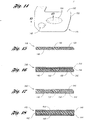
- Figures 14 and 15 show a door panel preform 146, manufactured according to the present invention, for use in manufacturing a finished door panel.
- the preform 146 has first and second regions 148 and 150, respectively, comprising selectively positioned virgin resin, and a third region 152 comprising selectively positioned waste plastic material.
- the first and second regions 148 and 150 correspond to areas that require relatively high performance characteristics, such as an armrest location and/or attachment points.
- performance characteristics such as strength and durability, in those regions can be maximized.
- overall cost of the preform 146 is reduced compared with preforms made entirely with virgin resin.
- the preform 146 further has an outline 153 that is preferably substantially similar to a desired outline of the finished door panel.
- one or more cover materials may be bonded to the preform 146, and the preform 146 may be shaped into the finished door panel. Because the outline 153 of the preform 146 is substantially similar to the desired outline of the finished door panel, minimal, if any, cutting and/or trimming of the preform 146 is required.
- Figure 16 shows a second embodiment 240 of the door panel preform manufactured according to the present invention.
- the preform 240 has first and second scrim layers 242 and 244, respectively, positioned above and below the first, second and third regions 148, 150 and 152, respectively, and a fiber layer 246.
- the scrim layers 242 and 244 provide additional strength to the preform 240, and may help inhibit warping of the preform 240 during and/or after a subsequent molding operation. While the scrim layers 242 and 244 may comprise any suitable material, the scrim layers 242 and 244 preferably comprise polyethylene terephthalate.
- the fiber layer 246 also provides additional strength to the preform 240, and preferably comprises natural fibers such as sisal, flax, kenaf, and/or jute.
- Figure 17 shows a third embodiment 340 of the door panel preform manufactured according to the present invention.
- the preform 340 includes first and second plastic films 342 and 344, respectively, positioned above and below the first, second and third regions 148, 150 and 152, respectively.
- the plastic films 342 and 344 provide substantially homogeneous, relatively high quality plastic exterior surfaces on the preform 340.
- the plastic films 342 and 344 preferably function to trap impurities and/or odors that may be associated with the waste plastic material. While the plastic films 342 and 344 may comprise any suitable plastic material, the plastic films 342 and 344 preferably comprise polypropylene.
- Figure 18 shows a fourth embodiment 440 of the door panel preform manufactured according to the present invention.
- the preform 440 includes a middle layer 442 of waste plastic material, first and second fiber layers 444 and 446, respectively, and first and second plastic films 448 and 450, respectively.
- the fiber layers 444 and 446 provide sufficient strength to the preform 440 for a particular application such that no virgin resin material is necessary.
- the fiber layers 444 and 446 preferably comprise natural fibers such as sisal, flax, kenaf, and/or jute.
- the plastic films 448 and 450 are similar in function and composition to the plastic films 342 and 344 of the preform 340.
- waste plastic material and other reinforcing material such as virgin resin
- waste plastic material and other reinforcing material such as virgin resin
- the reinforcing material layer is used to provide the necessary melt strength to the parison so that it can be blow molded.
- the parison may be extruded with at least two reinforcing material layers that encapsulate the waste plastic material layer and are configured to trap odors and/or impurities that may be associated with the waste plastic material layer.
Landscapes
- Engineering & Computer Science (AREA)
- Mechanical Engineering (AREA)
- Robotics (AREA)
- Environmental & Geological Engineering (AREA)
- Casting Or Compression Moulding Of Plastics Or The Like (AREA)
Applications Claiming Priority (2)
| Application Number | Priority Date | Filing Date | Title |
|---|---|---|---|
| US259090 | 1999-02-26 | ||
| US09/259,090 US6221291B1 (en) | 1999-02-26 | 1999-02-26 | Method for making a preform |
Publications (2)
| Publication Number | Publication Date |
|---|---|
| EP1031403A1 true EP1031403A1 (fr) | 2000-08-30 |
| EP1031403B1 EP1031403B1 (fr) | 2003-05-02 |
Family
ID=22983486
Family Applications (1)
| Application Number | Title | Priority Date | Filing Date |
|---|---|---|---|
| EP20000301407 Expired - Lifetime EP1031403B1 (fr) | 1999-02-26 | 2000-02-23 | Procédé de fabrication d'une préforme |
Country Status (3)
| Country | Link |
|---|---|
| US (1) | US6221291B1 (fr) |
| EP (1) | EP1031403B1 (fr) |
| DE (1) | DE60002383T2 (fr) |
Cited By (5)
| Publication number | Priority date | Publication date | Assignee | Title |
|---|---|---|---|---|
| FR2860450A1 (fr) * | 2003-10-03 | 2005-04-08 | Faurecia Automotive Ind | Procede de realisation d'une garniture a structure sandwich pour vehicule automobile et garniture ainsi obtenue. |
| WO2007090479A1 (fr) * | 2006-02-03 | 2007-08-16 | Carcoustics Techconsult Gmbh | Procede de fabrication de pieces moulees qui absorbent le son et dotees de parties de densites differentes |
| FR2905301A1 (fr) * | 2006-08-29 | 2008-03-07 | Faurecia Automotive Ind Snc | Nappe structurante pour garnissage d'automobile, et son procede de fabrication |
| WO2019054856A1 (fr) * | 2017-09-13 | 2019-03-21 | Better Future Factory B.V. | Procédé de transformation d'un thermoplastique en un élément monolithique tel qu'un carreau, un récipient et une combinaison d'un four, de moyens de transport et du récipient |
| EP4282612A1 (fr) * | 2022-05-27 | 2023-11-29 | Eurostyle Systems Tech Center France | Revêtement pour pièces visibles |
Families Citing this family (22)
| Publication number | Priority date | Publication date | Assignee | Title |
|---|---|---|---|---|
| KR20030007539A (ko) * | 2000-04-20 | 2003-01-23 | 데코마 익스테리어 트림 인크. | 패널 성형 방법 |
| US20020187291A1 (en) * | 2001-04-12 | 2002-12-12 | Jean-Michel Philippoz | Long solidified hollow thermoplastic articles |
| US20040048032A1 (en) * | 2002-09-06 | 2004-03-11 | Lear Corporation | Vehicle part and method of making the same |
| US20040110438A1 (en) * | 2002-12-10 | 2004-06-10 | Graham Tompson | Acoustic articles utilizing isocyanate binders and methods of making same |
| US8673188B2 (en) * | 2006-02-14 | 2014-03-18 | Goodrich Corporation | Carbon-carbon parts and methods for making same |
| US7921535B2 (en) * | 2007-10-19 | 2011-04-12 | Michael Noon | Method of setting up a machine for die cutting |
| GB201006391D0 (en) | 2010-04-16 | 2010-06-02 | Dyson Technology Ltd | Control of a brushless permanent-magnet motor |
| GB201006387D0 (en) | 2010-04-16 | 2010-06-02 | Dyson Technology Ltd | Control of a brushless motor |
| GB201006390D0 (en) | 2010-04-16 | 2010-06-02 | Dyson Technology Ltd | Control of a brushless motor |
| GB201006392D0 (en) | 2010-04-16 | 2010-06-02 | Dyson Technology Ltd | Controller for a brushless motor |
| GB201006396D0 (en) | 2010-04-16 | 2010-06-02 | Dyson Technology Ltd | Control of a brushless motor |
| GB201006398D0 (en) | 2010-04-16 | 2010-06-02 | Dyson Technology Ltd | Control of a brushless motor |
| GB201006388D0 (en) | 2010-04-16 | 2010-06-02 | Dyson Technology Ltd | Control of brushless motor |
| GB201006397D0 (en) | 2010-04-16 | 2010-06-02 | Dyson Technology Ltd | Control of a brushless motor |
| GB201006384D0 (en) * | 2010-04-16 | 2010-06-02 | Dyson Technology Ltd | Control of a brushless motor |
| GB201006386D0 (en) | 2010-04-16 | 2010-06-02 | Dyson Technology Ltd | Control of a brushless motor |
| GB201006395D0 (en) | 2010-04-16 | 2010-06-02 | Dyson Technology Ltd | Control of a brushless motor |
| US8536238B2 (en) | 2010-07-23 | 2013-09-17 | King Abdulaziz City For Science And Technology | Process for preparing insulation sheets from unseparated mixtures of post-consumer plastic articles |
| GB2484289B (en) | 2010-10-04 | 2013-11-20 | Dyson Technology Ltd | Control of an electrical machine |
| DE102011079243B4 (de) * | 2011-07-15 | 2022-06-30 | Lisa Dräxlmaier GmbH | Eingeprägte Rastverbindung |
| FR2987777B1 (fr) * | 2012-03-09 | 2014-05-02 | Faurecia Automotive Ind | Procede de fabrication d'une piece d'equipement de vehicule automobile et piece d'equipement associee |
| JP6626914B2 (ja) * | 2018-03-02 | 2019-12-25 | 株式会社エイ・ティ・エル | 樹脂ブロック製造装置及び樹脂ブロック製造方法 |
Citations (7)
| Publication number | Priority date | Publication date | Assignee | Title |
|---|---|---|---|---|
| EP0443051A1 (fr) * | 1990-02-17 | 1991-08-28 | FIBRON Gesellschaft mit beschränkter Haftung | Procédé de fabrication d'une matière à mouler thermodurcissable composite en fibres de verre-polyester et dispositif de réalisation du procédé |
| JPH05111917A (ja) * | 1991-10-22 | 1993-05-07 | Nissan Motor Co Ltd | リサイクルスタンパブルシートの製造方法 |
| EP0566830A1 (fr) * | 1992-02-20 | 1993-10-27 | ERCOM COMPOSITE RECYCLING GmbH KUNSTSTOFFAUFBEREITUNG | Procédé et installation pour la préparation d'une matière à mouler composite fibre/résine, en particulier d'un préimprégné |
| DE4215349A1 (de) * | 1992-05-09 | 1993-11-18 | Walter Voest | Verfahren zum Herstellen von Formteilen |
| JPH0679836A (ja) * | 1992-09-03 | 1994-03-22 | Hitachi Chem Co Ltd | 積層シート状成形材料及びそれを用いた成形品の製造法 |
| EP0638404A1 (fr) * | 1993-07-23 | 1995-02-15 | Palboard Ltd. | Procédé et dispositif pour la fabrication d'un produit en matière plastique |
| US5807513A (en) * | 1997-07-08 | 1998-09-15 | Ut Automotive Dearborn, Inc. | Recycling trim components |
Family Cites Families (7)
| Publication number | Priority date | Publication date | Assignee | Title |
|---|---|---|---|---|
| DE3208963C2 (de) | 1982-03-12 | 1985-06-27 | Deutsche Fibrit Gesellschaft Ebers & Dr. Müller mbH, 4150 Krefeld | Trockenverfahren zur Herstellung stark konturierter Vorformlinge aus defibrierten beleimten Holzfasern |
| US5041260A (en) | 1989-10-30 | 1991-08-20 | Ford Motor Company | Resin transfer molding method |
| US5229052A (en) | 1990-02-23 | 1993-07-20 | Wellman Machinery Of Michigan, Inc. | Apparatus and method for applying multiple type fibers to a foraminous surface |
| US5217672A (en) | 1992-08-06 | 1993-06-08 | Davidson Textron Inc. | Preform forming and curing process and an apparatus for the process |
| US5503788A (en) | 1994-07-12 | 1996-04-02 | Lazareck; Jack | Automobile shredder residue-synthetic plastic material composite, and method for preparing the same |
| US5575965A (en) | 1995-05-19 | 1996-11-19 | Union Carbide Chemicals & Plastics Technology Corporation | Process for extrusion |
| US5843365A (en) | 1997-01-06 | 1998-12-01 | Textron Automotive Company Inc. | Directed fiber preforming apparatus and method having fiber lay-up control |
-
1999
- 1999-02-26 US US09/259,090 patent/US6221291B1/en not_active Expired - Fee Related
-
2000
- 2000-02-23 EP EP20000301407 patent/EP1031403B1/fr not_active Expired - Lifetime
- 2000-02-23 DE DE2000602383 patent/DE60002383T2/de not_active Expired - Fee Related
Patent Citations (7)
| Publication number | Priority date | Publication date | Assignee | Title |
|---|---|---|---|---|
| EP0443051A1 (fr) * | 1990-02-17 | 1991-08-28 | FIBRON Gesellschaft mit beschränkter Haftung | Procédé de fabrication d'une matière à mouler thermodurcissable composite en fibres de verre-polyester et dispositif de réalisation du procédé |
| JPH05111917A (ja) * | 1991-10-22 | 1993-05-07 | Nissan Motor Co Ltd | リサイクルスタンパブルシートの製造方法 |
| EP0566830A1 (fr) * | 1992-02-20 | 1993-10-27 | ERCOM COMPOSITE RECYCLING GmbH KUNSTSTOFFAUFBEREITUNG | Procédé et installation pour la préparation d'une matière à mouler composite fibre/résine, en particulier d'un préimprégné |
| DE4215349A1 (de) * | 1992-05-09 | 1993-11-18 | Walter Voest | Verfahren zum Herstellen von Formteilen |
| JPH0679836A (ja) * | 1992-09-03 | 1994-03-22 | Hitachi Chem Co Ltd | 積層シート状成形材料及びそれを用いた成形品の製造法 |
| EP0638404A1 (fr) * | 1993-07-23 | 1995-02-15 | Palboard Ltd. | Procédé et dispositif pour la fabrication d'un produit en matière plastique |
| US5807513A (en) * | 1997-07-08 | 1998-09-15 | Ut Automotive Dearborn, Inc. | Recycling trim components |
Non-Patent Citations (2)
| Title |
|---|
| PATENT ABSTRACTS OF JAPAN vol. 017, no. 469 (M - 1469) 26 August 1993 (1993-08-26) * |
| PATENT ABSTRACTS OF JAPAN vol. 018, no. 335 (M - 1627) 24 June 1994 (1994-06-24) * |
Cited By (6)
| Publication number | Priority date | Publication date | Assignee | Title |
|---|---|---|---|---|
| FR2860450A1 (fr) * | 2003-10-03 | 2005-04-08 | Faurecia Automotive Ind | Procede de realisation d'une garniture a structure sandwich pour vehicule automobile et garniture ainsi obtenue. |
| WO2007090479A1 (fr) * | 2006-02-03 | 2007-08-16 | Carcoustics Techconsult Gmbh | Procede de fabrication de pieces moulees qui absorbent le son et dotees de parties de densites differentes |
| FR2905301A1 (fr) * | 2006-08-29 | 2008-03-07 | Faurecia Automotive Ind Snc | Nappe structurante pour garnissage d'automobile, et son procede de fabrication |
| WO2019054856A1 (fr) * | 2017-09-13 | 2019-03-21 | Better Future Factory B.V. | Procédé de transformation d'un thermoplastique en un élément monolithique tel qu'un carreau, un récipient et une combinaison d'un four, de moyens de transport et du récipient |
| EP4282612A1 (fr) * | 2022-05-27 | 2023-11-29 | Eurostyle Systems Tech Center France | Revêtement pour pièces visibles |
| FR3135912A1 (fr) * | 2022-05-27 | 2023-12-01 | Eurostyle Systems Tech Center France | Revêtement pour pièces visibles |
Also Published As
| Publication number | Publication date |
|---|---|
| DE60002383D1 (de) | 2003-06-05 |
| EP1031403B1 (fr) | 2003-05-02 |
| US6221291B1 (en) | 2001-04-24 |
| DE60002383T2 (de) | 2004-02-19 |
Similar Documents
| Publication | Publication Date | Title |
|---|---|---|
| US6221291B1 (en) | Method for making a preform | |
| US5888616A (en) | Vehicle interior component formed from recyclable plastics material | |
| US6890023B2 (en) | Reinforced composite inner roof panel of the cellular core sandwich-type and method of making same | |
| US20140070458A1 (en) | Method of molding composite plastic sheet material to form a compression molded, deep-drawn article | |
| US10005246B2 (en) | Methods for making interior panels for motor vehicles | |
| US10279512B2 (en) | Method of making a laminated trim component at a molding station | |
| US20190389097A1 (en) | Method of Making a Trim Component Having a Fibrous Decorative Covering | |
| CA2046424A1 (fr) | Structure fibreuse et piece moulee connexe, et procede de fabrication | |
| US20100032870A1 (en) | Method for the production of fiber-reinforced polypropylene molded parts containing pores | |
| US20040234744A1 (en) | Vehicle interior trim component of basalt fibers and thermoplastic binder and method of manufacturing the same | |
| US20190389103A1 (en) | Method of Making a Vehicle Interior Component Having an Integral Airbag Component and a Fibrous Decorative Covering | |
| GB2360485A (en) | Method of recycling scrap material containing a thermoplastic | |
| CN103770322A (zh) | 用于形成装饰板的铸模 | |
| US20150298369A1 (en) | Method for producing at least two-layer components, and component | |
| US20190389102A1 (en) | Method of Making a Trim Component Having an Edge-Wrapped, Fibrous Decorative Covering | |
| US20190389104A1 (en) | Method of Making a Vehicle Interior Component Having an Integral Airbag Component | |
| US10618203B2 (en) | Method of making a trimmed, laminated trim component | |
| US10166704B2 (en) | Method of making a laminated trim component at a pair of spaced first and second molding stations | |
| CN107257731A (zh) | 用于生产纤维增强的塑料零件的过程布置以及方法 | |
| CN107249865A (zh) | 用于生产纤维增强的塑料零件的过程布置以及方法 | |
| US5888913A (en) | Glass matt reinforced thermoplastics suitable for the production of paintable parts and parts produced therefrom | |
| EP3434458A1 (fr) | Procédé de fabrication d'une pièce moulée plate à partir d'un thermoplastique renforcé de fibres et pièce moulée ainsi fabriquée | |
| KR20230105028A (ko) | 차량용 헤드라이닝 제조방법 | |
| US10532499B2 (en) | Method of making a laminated trim component | |
| GB2387139A (en) | Manufacturing a composite panel |
Legal Events
| Date | Code | Title | Description |
|---|---|---|---|
| PUAI | Public reference made under article 153(3) epc to a published international application that has entered the european phase |
Free format text: ORIGINAL CODE: 0009012 |
|
| AK | Designated contracting states |
Kind code of ref document: A1 Designated state(s): DE GB IT SE |
|
| AX | Request for extension of the european patent |
Free format text: AL;LT;LV;MK;RO;SI |
|
| 17P | Request for examination filed |
Effective date: 20001201 |
|
| AKX | Designation fees paid |
Free format text: DE GB IT SE |
|
| 17Q | First examination report despatched |
Effective date: 20010608 |
|
| GRAH | Despatch of communication of intention to grant a patent |
Free format text: ORIGINAL CODE: EPIDOS IGRA |
|
| GRAH | Despatch of communication of intention to grant a patent |
Free format text: ORIGINAL CODE: EPIDOS IGRA |
|
| GRAA | (expected) grant |
Free format text: ORIGINAL CODE: 0009210 |
|
| AK | Designated contracting states |
Designated state(s): DE GB IT SE |
|
| PG25 | Lapsed in a contracting state [announced via postgrant information from national office to epo] |
Ref country code: IT Free format text: LAPSE BECAUSE OF FAILURE TO SUBMIT A TRANSLATION OF THE DESCRIPTION OR TO PAY THE FEE WITHIN THE PRESCRIBED TIME-LIMIT;WARNING: LAPSES OF ITALIAN PATENTS WITH EFFECTIVE DATE BEFORE 2007 MAY HAVE OCCURRED AT ANY TIME BEFORE 2007. THE CORRECT EFFECTIVE DATE MAY BE DIFFERENT FROM THE ONE RECORDED. Effective date: 20030502 |
|
| REG | Reference to a national code |
Ref country code: GB Ref legal event code: FG4D |
|
| REF | Corresponds to: |
Ref document number: 60002383 Country of ref document: DE Date of ref document: 20030605 Kind code of ref document: P |
|
| PG25 | Lapsed in a contracting state [announced via postgrant information from national office to epo] |
Ref country code: SE Free format text: LAPSE BECAUSE OF FAILURE TO SUBMIT A TRANSLATION OF THE DESCRIPTION OR TO PAY THE FEE WITHIN THE PRESCRIBED TIME-LIMIT Effective date: 20030802 |
|
| PLBE | No opposition filed within time limit |
Free format text: ORIGINAL CODE: 0009261 |
|
| STAA | Information on the status of an ep patent application or granted ep patent |
Free format text: STATUS: NO OPPOSITION FILED WITHIN TIME LIMIT |
|
| 26N | No opposition filed |
Effective date: 20040203 |
|
| REG | Reference to a national code |
Ref country code: GB Ref legal event code: 732E |
|
| PGFP | Annual fee paid to national office [announced via postgrant information from national office to epo] |
Ref country code: GB Payment date: 20070223 Year of fee payment: 8 |
|
| PGFP | Annual fee paid to national office [announced via postgrant information from national office to epo] |
Ref country code: DE Payment date: 20070330 Year of fee payment: 8 |
|
| GBPC | Gb: european patent ceased through non-payment of renewal fee |
Effective date: 20080223 |
|
| PG25 | Lapsed in a contracting state [announced via postgrant information from national office to epo] |
Ref country code: DE Free format text: LAPSE BECAUSE OF NON-PAYMENT OF DUE FEES Effective date: 20080902 |
|
| PG25 | Lapsed in a contracting state [announced via postgrant information from national office to epo] |
Ref country code: GB Free format text: LAPSE BECAUSE OF NON-PAYMENT OF DUE FEES Effective date: 20080223 |