EP1031501A2 - Assemblage magnétique pour dispositif de surveillance de bicyclette - Google Patents
Assemblage magnétique pour dispositif de surveillance de bicyclette Download PDFInfo
- Publication number
- EP1031501A2 EP1031501A2 EP00103819A EP00103819A EP1031501A2 EP 1031501 A2 EP1031501 A2 EP 1031501A2 EP 00103819 A EP00103819 A EP 00103819A EP 00103819 A EP00103819 A EP 00103819A EP 1031501 A2 EP1031501 A2 EP 1031501A2
- Authority
- EP
- European Patent Office
- Prior art keywords
- spoke
- housing
- magnetic
- side walls
- predetermined distance
- Prior art date
- Legal status (The legal status is an assumption and is not a legal conclusion. Google has not performed a legal analysis and makes no representation as to the accuracy of the status listed.)
- Granted
Links
- 238000012806 monitoring device Methods 0.000 title claims abstract description 15
- 239000000696 magnetic material Substances 0.000 claims 1
- 239000000463 material Substances 0.000 description 6
- 238000009434 installation Methods 0.000 description 5
- 230000036961 partial effect Effects 0.000 description 5
- 229920003023 plastic Polymers 0.000 description 4
- 239000013013 elastic material Substances 0.000 description 3
- 239000013536 elastomeric material Substances 0.000 description 3
- 239000003562 lightweight material Substances 0.000 description 3
- 230000000295 complement effect Effects 0.000 description 2
- 230000003247 decreasing effect Effects 0.000 description 2
- 239000006249 magnetic particle Substances 0.000 description 2
- 230000005389 magnetism Effects 0.000 description 2
- 230000002829 reductive effect Effects 0.000 description 2
- 239000012858 resilient material Substances 0.000 description 2
- 241000587161 Gomphocarpus Species 0.000 description 1
- 235000014676 Phragmites communis Nutrition 0.000 description 1
- 238000005452 bending Methods 0.000 description 1
- 230000015556 catabolic process Effects 0.000 description 1
- 230000002860 competitive effect Effects 0.000 description 1
- 238000010276 construction Methods 0.000 description 1
- 230000001351 cycling effect Effects 0.000 description 1
- 229920002457 flexible plastic Polymers 0.000 description 1
- 230000000670 limiting effect Effects 0.000 description 1
- 238000004519 manufacturing process Methods 0.000 description 1
- 238000012986 modification Methods 0.000 description 1
- 230000004048 modification Effects 0.000 description 1
- 230000036963 noncompetitive effect Effects 0.000 description 1
- 230000000717 retained effect Effects 0.000 description 1
- 230000003313 weakening effect Effects 0.000 description 1
Images




Classifications
-
- B—PERFORMING OPERATIONS; TRANSPORTING
- B62—LAND VEHICLES FOR TRAVELLING OTHERWISE THAN ON RAILS
- B62J—CYCLE SADDLES OR SEATS; AUXILIARY DEVICES OR ACCESSORIES SPECIALLY ADAPTED TO CYCLES AND NOT OTHERWISE PROVIDED FOR, e.g. ARTICLE CARRIERS OR CYCLE PROTECTORS
- B62J45/00—Electrical equipment arrangements specially adapted for use as accessories on cycles, not otherwise provided for
- B62J45/40—Sensor arrangements; Mounting thereof
- B62J45/42—Sensor arrangements; Mounting thereof characterised by mounting
Definitions
- This invention generally relates to a magnetic assembly for a bicycle monitoring device. More specifically, the present invention relates a magnetic assembly which includes a magnetic device that mounts on a special spoke of a wheel such that the magnetic device remains in a predetermined location on the spoke.
- One object of the present invention is to provide a magnetic assembly that is relatively easy to install on a spoke such that the magnetic device does not rotate or move longitudinally along the axis of the spoke.
- Another object of the present invention is to provide a magnetic device that is inexpensive to manufacture.
- Another object of the present invention is to provide a magnetic device that can be installed in one step.
- the foregoing objects basically can be obtained by providing a magnetic assembly for a bicycle monitoring device.
- the magnetic assembly includes a spoke and a magnetic housing.
- the spoke has a first end, a second end and a connecting portion extending between the first and second ends.
- the magnetic housing has a spoke-receiving recess with a pair of opposed side walls spaced apart by a first predetermined distance to retain the spoke therebetween.
- Either the spoke or the housing has a projection extending therefrom and the other of the spoke or the housing has a concavity for engaging the projection when the spoke is located within the spoke-receiving recess.
- the foregoing objects basically can be obtained by providing a spoke is provided for attaching a magnetic housing thereto.
- the spoke includes a first attachment end, a second attachment end and a connecting portion.
- the first attachment end is configured and adapted to be coupled to a corresponding structure of a hub.
- the second attachment end is configured and adapted to be coupled to a corresponding structure of a rim.
- the connecting portion extends between the first and second ends.
- the connecting portion is with a concavity.
- This spoke is used with a magnetic device having a spoke-receiving recess having a complementary projection.
- a spoke for attaching a magnetic housing thereto.
- the spoke includes a first attachment end, a second attachment end and a connecting portion.
- the first attachment end is configured and adapted to be coupled to a corresponding structure of a hub.
- the second attachment end is configured and adapted to be coupled to a corresponding structure of a rim.
- the connecting portion extends between the first and second ends.
- the connecting portion is provided with a projection.
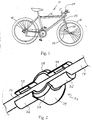
- a bicycle 10 is illustrated with a monitoring device 12 mounted thereon in accordance with the present invention.
- Bicycles and their various components are well known in the art, and thus, bicycle 10 and its various components will not be discussed or illustrated in detail herein except for the components that relate to the present invention. In other words, only monitoring device 12 and the components of bicycle 10 relating thereto will be discussed and/or illustrated herein.
- Bicycle 10 basically includes a frame 14, a pair of wheels 16 and handlebar 17.
- the bicycle frame 14 has handlebar 18 movably attached thereto for turning front wheel 16.
- Each of the wheels 16 are conventional wheels that are rotatably coupled to frame 14 in a conventional manner.
- Each of the wheels 16 has a hub 18, a plurality of spokes 19 and a rim 20. Spokes 19 of each of the wheels 16 extend between hub 18 and rim 20. While the hubs 18 for the wheels 16 are different in the front and rear wheels, these differences are not important to this invention.
- Spoke 19 has first attachment end 21, second attachment end 22 and a connecting portion 23 extending therebetween.
- First attachment end 21 can be adapted to be coupled to the corresponding structure of the hub 18.
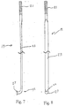
- First attachment end 21 is threaded as shown in Figures 7 and 8.
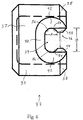
- Second attachment end 22 has a head 27 in the shape of a bent nail head as shown in Figure 6.
- Second attachment end 22 can be adapted to be coupled to rim 20 of wheel 16.
- flat spoke 19 can be reversed, so that first attachment end 21 is coupled to rim 20, and second attachment end is coupled to hub 18.
- Connecting portion 23 has a non-circular cross-sectional, preferably substantially elliptical cross-section.
- spokes 19 are so-called flat or aerodynamic spokes. Spokes 19 differ from round spokes in that they have a substantially elliptical cross-section, where that cross-section has rounded ends.
- the cross-sectional length of flat spoke 19 is preferably around 2.75 millimeters.
- Flat spokes 19 are aligned along hub 18 of wheel 16 so as to decrease wind resistance. This decrease in wind resistance is due to the flattened surface of spoke 19 which lies in the same center plane as wheel 16. Thus, flat spokes 19 are very desirable in bicycle riding.
- Monitoring device 12 is adapted to be fixedly coupled to frame 14, handlebar 17 and one of the spokes 19 of one of the wheels 16.
- monitoring device 12 is especially designed for mounting on spoke 19 that has a portion with a non-circular cross-section.
- the monitoring device 12 basically includes four parts.
- monitoring device 12 basically includes a display unit 24, a wire 25, a sensor 26 and a magnetic device 28. All of the parts are basically conventional parts that are well known in the bicycle art, except for magnetic device 28 which is the subject of the present invention. Therefore, the display unit 24, wire 25 and sensor 26 will not be discussed or illustrated in detail herein.
- U.S. Patent No. 5,264,791 which is assigned to Cat Eye Incorporated.
- This U.S. patent is hereby incorporated herein by reference for the purpose of understanding one particular use of the magnetic device 28 in accordance with the present invention. Accordingly, display unit 24 mentioned above can be of the type mentioned in this U.S. patent or any other prior art device.
- the sensor 26 can be a reed switch or any other type of magnetic sensor that is known in the art.
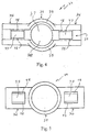
- Magnetic device 28 basically includes a magnet 30 and housing 32.
- Housing 32 is integrally formed as a one-piece unitary member, preferably of lightweight material.
- housing 32 can be molded as a one-piece, unitary member from plastic types of materials that can accomplish the essence of the present invention.
- Housing 32 can also be referred to as a bracket assembly.
- Housing 32 can alternatively be made of magnetic or magnetized material, and thus, eliminate the need for a separate magnet 30.
- housing 32 can be constructed of a plastic material with magnetic particles embedded therein. In any case, the construction of the material for housing 32 of magnetic device 28 is preferably lightweight.
- Magnetic device 28 should have a magnetism that is strong enough to operate sensor 26 without difficulty during rotation of wheel 16.
- Housing 32 has a body portion 34 and two retaining portions 36 extending from body portion 34.
- Body portion 34 can be cylindrical in shape.
- Housing 32 is preferably constructed of a lightweight material such as a resilient plastic.
- Housing 32 should be of a resilient material to releasably couple spoke 19 thereto.
- Body portion 34 has a cylindrical cavity 37 for holding magnet 30, with two semi-circular flanges 38 formed at the open end of cavity 37.
- Semi-circular flanges 38 are arranged to receive a portion of spoke 19 therebetween when housing 32 is completely installed on one of the spokes 19, and are molded in such a way as to be less likely to break off during handling of housing 32.
- the two retaining portions 36 are integrally formed with body portion 34 and extend in opposite directions from body portion 34.
- retaining portions 36 are integrally formed with body portion 34 as a one-piece, unitary member.
- Retaining portions 36 are channel-shaped to form a spoke-receiving recess 39.
- Each of the retaining portions 36 has a bottom wall 40 and two side walls 42.
- Each bottom wall 40 of each retaining portion 36 has an aperture 43 for decreasing weight of housing 32, and increasing flexibility.
- the two side walls 42 and bottom wall 40 extend outward from body portion 34.
- Side walls 42 are substantially parallel to each other and also extend substantially perpendicular to the bottom wall 40.
- Side walls 42 are spaced apart from each other by a predetermined distance B except along detents 48.
- each side wall 42 has detents 48 for holding and securing flat spoke 19 via a snap-fit.
- each side wall 42 has two detents 48 that are longitudinally spaced apart from each other along spoke-receiving recess 35.
- Each detent 48 has a curved outer surface 52 for inserting flat spoke 19.
- Each detent 48 also has an inner retaining surface 54.
- Side walls 42 and detent 48 form an opening 46 through which flat spoke 19 can be inserted beneath detent 48.
- Each retaining portion 36 is flexible so that it can move slightly outwardly to expand the spoke-receiving recess 39 as flat spoke 19 passes into opening 46.
- the opposing detents 48 are separated from each other by a predetermined distance C.
- This spoke-receiving recess 39 has a cross-sectional shape of an oval or racetrack, with rounded ends 56, as shown in Figure 6.
- Spoke-receiving recess 39 preferably has a length between approximately 10 millimeters and 30 millimeters, preferably around 18 millimeters.
- housing 32 is then rotated about the axis of flat spoke 19, so that the rounded ends 56 match up with rounded ends of spoke 19.
- This matching up of surfaces acts to snap-fit spoke 19 into spoke-receiving recess 50.
- housing 32 can be made of a more elastic material, so that detents 48 could become optional, and the snap-fit is replaced by an elastic fit as in a subsequent embodiment discussed below.
- the bottom wall 40 is spaced from inner retaining surfaces 54 by a predetermined distance A. It is an important feature of this invention that, as shown in Figure 6, distance A be less than distance B, so that housing 32 will more accurately fit the shape of spoke 19. This results in housing 32 not rotating about the axis of the spoke 19, and also orients housing 32 to activate sensor 26.
- opening 46 is smaller than spoke-receiving recess 39 (distance B). This contributes to the snap-fit of housing 32 around the flat portion of spoke 19. Also, housing 32 will have a reduced tendency to work loose from the flat portion of spoke 19, and will remain in place more effectively.
- housing 32 is pressed against spoke 19.
- detents 48 resist the centerward motion of flat spoke 19, but being made of flexible plastic, can yield to a slight degree.
- each detent 48 has a curved outer surface which assists in the flat portion of spoke 19 passing through opening 46.
- the installer exerts pressure on housing 32 during installation, detents 48 are forced radially outward from the center axis of spoke-receiving recess 39.
- side walls 42 spring back to return to their original positions.
- inner retaining surfaces 54 engage the flat portion of spoke 19 to hold spoke 19 against the bottom wall 40 of the spoke-receiving recess 39 with a slight pressing force.
- housing 32 is frictional retained on spoke 19 to substantially prevent longitudinal movement of magnetic device 12 along the longitudinal axis of spoke 19.
- housing 32 is snap-fitted, secured by detents 48 applying continual pressure, and very light in weight, no further securing means, such as a screw or a cover, is necessary. Another advantage is that housing 32 is less likely than conventional art to rotate out of position during use, because rounded ends of spoke-receiving recess 39 can more effectively grip rounded ends of flat spoke 19. Also, because of its snap-fit characteristics, housing 32 can be can be installed in one step, and requires no tools for installation.
- FIG. 9-12 a magnetic device 128 is illustrated in accordance with another embodiment of the present invention.
- this embodiment will not be discussed or illustrated in detail. Rather, it will be apparent to those skilled in the art from this disclosure that the most of the parts and descriptions of the prior embodiments also apply to the similar or identical parts of this embodiment.
- housing 132 is constructed of an elastic material, and detents 148 are optional.
- the term "elastic” as used hereinafter can include materials with some plastic deformation. In any event, the elastic material should substantially return to its initial form or state after being deformed. Thus, magnetic device 128 can be repeatedly installed, removed, and reinstalled, without significantly affecting the shape of housing 132.
- the magnetic device 128 can comprise a magnet 130 and housing 132.
- housing 132 is constructed of a lightweight elastomeric material, having elastic properties.
- the cross-sectional length B' of spoke-receiving recess is slightly smaller than the cross-sectional width D of the flat portion of spoke 119.
- length or distance B' is approximately 2.5 millimeters and the flat portion of spoke 119 has a cross-sectional width D of approximately 2.75 millimeters. Accordingly, housing 132 elastically grips the flat portion of spoke 119. Thus, housing 132 will remain in place more effectively.
- Housing 132 is integrally formed as a one-piece unitary member, preferably of lightweight material.
- housing 132 can be molded as a one-piece, unitary member from an elastomeric material that can accomplish the essence of the present invention.
- Housing 132 can also be referred to as a bracket assembly.
- Housing 132 can alternatively be made of magnetic or magnetized material, and thus, eliminate the need for a separate magnet 130.
- housing 132 can be constructed of an elastomeric material with magnetic particles embedded therein.
- Magnetic device 128 should have a magnetism that is strong enough to operate sensor 26 without difficulty during rotation of wheel 16.
- Housing 132 has a body portion 134 and two retaining portions 136 extending from body portion 134.
- Body portion 134 can be cylindrical in shape.
- Housing 132 should be of a resilient material to releasably couple spoke 119 thereto.
- Body portion 134 has a cavity 137 for holding magnet 130, with two semi-circular flanges 138 formed at the open end of cavity 137.
- Semi-circular flanges 138 are arranged to receive a flat portion of spoke 119 therebetween when housing 132 is completely installed on one of the spokes 119.
- Retaining portions 136 are channel-shaped to form a spoke-receiving recess 139.
- Each of the retaining portions 136 has a bottom wall 140 and two side walls 142.
- Each bottom wall 140 of each retaining portion 136 has an aperture 143 for decreasing weight of housing 132, and increasing flexibility.
- the two side walls 142 and bottom wall 140 extend outward from body portion 134.
- Side walls 142 are substantially parallel to each other and also extend substantially perpendicular to the bottom wall 140.
- Side walls 142 are spaced apart from each other by a predetermined distance B except along detents 148.
- Side walls 142 can optionally have detents 148 for further holding and securing flat surface of spoke 19 via an elastic fit.
- each side wall 142 has two detents 148 that are longitudinally spaced apart from each other along spoke-receiving recess 35.
- Each detent 148 has a curved outer surface 152 for inserting spoke 119.
- Each detent 148 also has an inner retaining surface 154.
- Side walls 142 and detents 148 form an opening 146 through which spoke 119 can be inserted beneath detents 148.
- Each retaining portion 136 is flexible so that it can move slightly outwardly to expand the spoke-receiving recess 139 as flat surface of spoke 119 passes into opening 146.
- This spoke-receiving recess 139 has a cross-sectional shape of an oval or racetrack, with rounded ends 156, as shown in Figure 11.
- Spoke-receiving recess 139 preferably has a length between approximately 10 millimeters and 30 millimeters, preferably around 18 millimeters.
- Detents 48 are optional in this embodiment since that spoke 119 is held within spoke-receiving recess 139 by an elastic fit.
- the bottom wall 140 is spaced from inner retaining surfaces 154 by a predetermined distance A. As shown in Figure 11, distance A be less than distance B', so that housing 132 will more accurately fit the shape of flat portion of spoke 119. This prevents housing 132 from rotating about the axis of the spoke 119, and also orients housing 132 to activate sensor 26.
- opening 146 (distance C) is smaller than spoke-receiving recess 139 (distance B'). This contributes to the elastic fit of housing 132 around flat portion of spoke 119. Thus, housing 132 will have a reduced tendency to work loose from the flat portion of spoke 119, and will remain in place more effectively.
- cross-sectional length of flat section of spoke 119 (distance D) is larger than distance B'.
- Distance D is preferably around 2.75 millimeters, and distance B' is preferably around 2.5 millimeters. Because spoke-receiving recess 139 is smaller than spoke 119, the elastic properties of housing 132 will cause side walls 142 to push against flat surface of spoke 119. This will increase the gripping force of housing 132 on flat surface of spoke 119.
- Magnetic device 228 is designed to be used with monitoring device 12 of Figure 1.
- This third embodiment of the magnetic device 228 is substantially identical to the prior embodiments, except that a projection 257 is provided on the housing 232 and the spoke 219 is provided with a concavity 258.
- housing 232 can be dimensioned to have a snap-fit configuration or an elastic fit configuration.
- magnetic device 228 of this embodiment can be used with a variety of spokes, e.g., round, elliptical or flat.
- this embodiment will not be discussed or illustrated in detail. Rather, it will be apparent to those skilled in the art from this disclosure that the various parts and descriptions of the prior embodiments apply to the similar or identical parts of this embodiment.
- Housing 232 can have magnet 230, body portion 234, and retaining portions 236.
- Retaining portions 236 are channel-shaped to form a spoke-receiving recess 239.
- Each of the retaining portions 236 has a bottom wall 240 and two side walls 242.
- Bottom wall 240, side walls 242, and two detents 248 together form spoke-receiving recess 239.
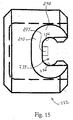
- This spoke-receiving recess 239 has a cross-sectional shape of an oval or racetrack, with rounded ends 256, as shown in Figure 15.
- Housing 232 also has a projection 257 formed from bottom wall 240 of one of the retaining portions 236. The projection 257 extends outward approximately 0.7 millimeters.
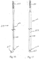
- Spoke 219 has a corresponding concave surface 258, as shown in Figures 16 and 17, for accommodating projection 257. This matching up of projection 257 to concave surface or concavity 258 acts to further secure spoke 219 into spoke-receiving recess 239, and prevent relative movement between spoke 219 and housing 232.
- Magnetic device 328 is illustrated in accordance with another embodiment of the present invention.
- Magnetic device 328 is designed to be used with monitoring device 12 of Figure 1.
- This fourth embodiment of the magnetic device 328 is substantially identical to the prior embodiments, except that a projection 357 is provided on the spoke 319 and housing 332 is provided with a concavity 358.
- housing 332 can be dimensioned to have a snap-fit configuration or an elastic fit configuration.
- magnetic device 328 of this embodiment can be used with a variety of spokes, e.g., round, elliptical or flat.
- this embodiment will not be discussed or illustrated in detail. Rather, it will be apparent to those skilled in the art from this disclosure that the various parts and descriptions of the prior embodiments apply to the similar or identical parts of this embodiment.
- Housing 332 can have magnet 330, body portion 334, and retaining portions 236.
- Retaining portions 336 are channel-shaped to form a spoke-receiving recess 339.
- Each of the retaining portions 336 has a bottom wall 340 and two side walls 342.
- Bottom wall 340, side walls 342, and two detents 348 together form spoke-receiving recess 339.
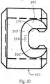
- This spoke-receiving recess 339 has a cross-sectional shape of an oval or racetrack, with rounded ends 356, as shown in Figure 20.
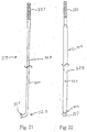
- spoke 319 also has a projection 357 formed from its surface.
- Housing 332 has a corresponding concave surface 358 in one of its retaining walls 336, as shown in Figure 20, for accommodating projection 357. This matching up of projection 357 to concave surface or concavity 358 acts to further secure spoke 319 into spoke-receiving recess 339, and prevent relative movement between spoke 319 and housing 332.
Landscapes
- Engineering & Computer Science (AREA)
- Mechanical Engineering (AREA)
- Transmission And Conversion Of Sensor Element Output (AREA)
- Measuring Volume Flow (AREA)
- Looms (AREA)
- Burglar Alarm Systems (AREA)
- Force Measurement Appropriate To Specific Purposes (AREA)
- Level Indicators Using A Float (AREA)
- Regulating Braking Force (AREA)
Applications Claiming Priority (2)
| Application Number | Priority Date | Filing Date | Title |
|---|---|---|---|
| US09/255,345 US6188215B1 (en) | 1999-02-23 | 1999-02-23 | Magnetic assembly for a bicycle monitoring device |
| US255345 | 1999-02-23 |
Publications (3)
| Publication Number | Publication Date |
|---|---|
| EP1031501A2 true EP1031501A2 (fr) | 2000-08-30 |
| EP1031501A3 EP1031501A3 (fr) | 2001-01-17 |
| EP1031501B1 EP1031501B1 (fr) | 2004-04-28 |
Family
ID=22967900
Family Applications (1)
| Application Number | Title | Priority Date | Filing Date |
|---|---|---|---|
| EP00103819A Expired - Lifetime EP1031501B1 (fr) | 1999-02-23 | 2000-02-23 | Assemblage magnétique pour dispositif de surveillance de bicyclette |
Country Status (6)
| Country | Link |
|---|---|
| US (1) | US6188215B1 (fr) |
| EP (1) | EP1031501B1 (fr) |
| JP (1) | JP2000238682A (fr) |
| CN (1) | CN1183002C (fr) |
| DE (1) | DE60010153T2 (fr) |
| TW (1) | TWI246484B (fr) |
Families Citing this family (6)
| Publication number | Priority date | Publication date | Assignee | Title |
|---|---|---|---|---|
| ITTO20010783A1 (it) * | 2001-08-03 | 2003-02-03 | Campagnolo Srl | Cuscinetto anti-attrito interponibile all'incrocio fra due raggi di una ruota di bicicletta. |
| DE602004012378T2 (de) * | 2004-01-27 | 2009-04-23 | Campagnolo S.R.L. | Speiche für Fahrradrad und Fahrradrad eine solche Speiche enthaltend sowie Herstellverfahren für eine solche Speiche |
| DE102004041832B3 (de) | 2004-08-27 | 2005-12-08 | Cycle Parts Gmbh | Magnetischer Impulsgeber |
| EP1724122A1 (fr) * | 2005-05-16 | 2006-11-22 | Campagnolo S.R.L. | Rayon pour roue de bicyclette et roue de bicyclette comprenant un tel rayon |
| DE102008031939A1 (de) | 2008-07-07 | 2010-01-14 | Brügge, Jürgen, Dipl.-Ing. | Weggeber für einen Fahrradtachometer |
| WO2012019654A1 (fr) | 2010-10-15 | 2012-02-16 | Ar Innovation Ag | Capteur et procédé de détermination de la cadence d'actionnement des pédales et de la vitesse de déplacement d'une bicyclette |
Citations (1)
| Publication number | Priority date | Publication date | Assignee | Title |
|---|---|---|---|---|
| US5624791A (en) | 1989-04-28 | 1997-04-29 | Fujitsu Ltd. | Pattern forming method using mask |
Family Cites Families (11)
| Publication number | Priority date | Publication date | Assignee | Title |
|---|---|---|---|---|
| US3854777A (en) | 1973-05-21 | 1974-12-17 | Beatrice Foods Co | Spoke mountable bracket assembly |
| US3898563A (en) | 1973-11-15 | 1975-08-05 | David E Erisman | Solid state bicycle speedometer, tachometer, and odometer device |
| US4331918A (en) | 1980-05-21 | 1982-05-25 | Basta Laasefabrik A/S | Speedometer for cycles and mopeds |
| US4352063A (en) | 1981-05-08 | 1982-09-28 | Jones Peter W J | Self-calibrating speedometer/odometer |
| JPS5827770U (ja) * | 1981-08-18 | 1983-02-22 | 株式会社津山金属製作所 | 回転速度等の検出部取付装置 |
| DE3226357C2 (de) * | 1982-07-14 | 1985-07-25 | K.W. Hochschorner Gmbh, 8035 Stockdorf | Vorrichtung zur Messung der mit einem Fahrrad zurückgelegten Wegstrecke |
| JPS59106301A (ja) * | 1982-12-11 | 1984-06-20 | Daido Kogyo Co Ltd | ワイヤ−スポ−ク車輪 |
| JPH0642208Y2 (ja) | 1989-11-15 | 1994-11-02 | 株式会社キャットアイ | センサマグネット取付装置 |
| JPH04104572U (ja) | 1991-02-18 | 1992-09-09 | 株式会社キヤツトアイ | センサユニツト |
| DE9202393U1 (de) * | 1992-02-25 | 1992-04-16 | Chou, Ming-Fu, Tai-Chung | Haltevorrichtung für einen Magneten eines Umdrehungszählers an einem Fahrrad |
| JPH0723692A (ja) | 1993-07-06 | 1995-01-27 | Marudai Shokuhin Kk | 湾曲した押出し練肉製品の製造方法及び製造用ノズル |
-
1999
- 1999-02-23 US US09/255,345 patent/US6188215B1/en not_active Expired - Fee Related
-
2000
- 2000-01-18 TW TW089100729A patent/TWI246484B/zh not_active IP Right Cessation
- 2000-02-22 CN CNB001022954A patent/CN1183002C/zh not_active Expired - Fee Related
- 2000-02-23 JP JP2000046069A patent/JP2000238682A/ja active Pending
- 2000-02-23 DE DE60010153T patent/DE60010153T2/de not_active Expired - Fee Related
- 2000-02-23 EP EP00103819A patent/EP1031501B1/fr not_active Expired - Lifetime
Patent Citations (1)
| Publication number | Priority date | Publication date | Assignee | Title |
|---|---|---|---|---|
| US5624791A (en) | 1989-04-28 | 1997-04-29 | Fujitsu Ltd. | Pattern forming method using mask |
Also Published As
| Publication number | Publication date |
|---|---|
| US6188215B1 (en) | 2001-02-13 |
| EP1031501B1 (fr) | 2004-04-28 |
| CN1183002C (zh) | 2005-01-05 |
| EP1031501A3 (fr) | 2001-01-17 |
| DE60010153D1 (de) | 2004-06-03 |
| JP2000238682A (ja) | 2000-09-05 |
| DE60010153T2 (de) | 2005-04-14 |
| CN1264665A (zh) | 2000-08-30 |
| TWI246484B (en) | 2006-01-01 |
Similar Documents
| Publication | Publication Date | Title |
|---|---|---|
| USRE39781E1 (en) | Bracket assembly, especially for use as a magnetic device in a monitoring device | |
| US20020025220A1 (en) | Magnet mounting structure | |
| US6188215B1 (en) | Magnetic assembly for a bicycle monitoring device | |
| JP2602582Y2 (ja) | 自転車用取付部品 | |
| JP2001246904A (ja) | ディスクブレーキ用自転車ハブ | |
| JPH09240567A (ja) | 自転車変速装置用制御装置 | |
| EP1988007A1 (fr) | Dispositif de détection pour bicyclette | |
| TWI568631B (zh) | 曲柄可拆卸支持器 | |
| JP3578718B2 (ja) | タンジェントスポーク用自転車ハブ | |
| US6339323B1 (en) | Noise reduction for a bicycle spoke, especially useful as a magnetic device | |
| US8234952B2 (en) | Handgrip for handlebar | |
| US6634758B2 (en) | Vehicle handlebar mirror system | |
| EP1728711B1 (fr) | Agencement de capteur de mouvement pour bicyclette | |
| EP1122095A2 (fr) | Moyeu de bicyclette à rayons avec dispositif d'étanchéité | |
| US9090124B2 (en) | Bicycle hub axle adapter | |
| JP4691558B2 (ja) | とりわけ自転車等の車輪回転数を測定するための磁気パルス発生装置 | |
| US6178850B1 (en) | Bicycle pedal | |
| EP0791530A2 (fr) | Dispositif de frein à cantilever | |
| JPH074278U (ja) | 自転車走行用計器の取付用補助具 | |
| JPS5828882Y2 (ja) | 車輛におけるエアセンサ−の取付装置 | |
| JPH04135995A (ja) | 自転車用速度表示装置 | |
| JPH1183879A (ja) | 車輪速センサの固定構造 | |
| HK1118036B (en) | Sensor device |
Legal Events
| Date | Code | Title | Description |
|---|---|---|---|
| PUAI | Public reference made under article 153(3) epc to a published international application that has entered the european phase |
Free format text: ORIGINAL CODE: 0009012 |
|
| AK | Designated contracting states |
Kind code of ref document: A2 Designated state(s): DE FR GB IE IT NL |
|
| AX | Request for extension of the european patent |
Free format text: AL;LT;LV;MK;RO;SI |
|
| PUAL | Search report despatched |
Free format text: ORIGINAL CODE: 0009013 |
|
| AK | Designated contracting states |
Kind code of ref document: A3 Designated state(s): AT BE CH CY DE DK ES FI FR GB GR IE IT LI LU MC NL PT SE |
|
| AX | Request for extension of the european patent |
Free format text: AL;LT;LV;MK;RO;SI |
|
| RIC1 | Information provided on ipc code assigned before grant |
Free format text: 7B 62J 39/00 A, 7B 62J 11/00 B |
|
| 17P | Request for examination filed |
Effective date: 20010216 |
|
| AKX | Designation fees paid |
Free format text: DE FR GB IE IT NL |
|
| GRAP | Despatch of communication of intention to grant a patent |
Free format text: ORIGINAL CODE: EPIDOSNIGR1 |
|
| GRAS | Grant fee paid |
Free format text: ORIGINAL CODE: EPIDOSNIGR3 |
|
| GRAA | (expected) grant |
Free format text: ORIGINAL CODE: 0009210 |
|
| AK | Designated contracting states |
Kind code of ref document: B1 Designated state(s): DE FR GB IE IT NL |
|
| REG | Reference to a national code |
Ref country code: GB Ref legal event code: FG4D |
|
| REG | Reference to a national code |
Ref country code: IE Ref legal event code: FG4D |
|
| REF | Corresponds to: |
Ref document number: 60010153 Country of ref document: DE Date of ref document: 20040603 Kind code of ref document: P |
|
| ET | Fr: translation filed | ||
| PLBE | No opposition filed within time limit |
Free format text: ORIGINAL CODE: 0009261 |
|
| STAA | Information on the status of an ep patent application or granted ep patent |
Free format text: STATUS: NO OPPOSITION FILED WITHIN TIME LIMIT |
|
| 26N | No opposition filed |
Effective date: 20050131 |
|
| PGFP | Annual fee paid to national office [announced via postgrant information from national office to epo] |
Ref country code: NL Payment date: 20060215 Year of fee payment: 7 |
|
| PGFP | Annual fee paid to national office [announced via postgrant information from national office to epo] |
Ref country code: FR Payment date: 20060220 Year of fee payment: 7 Ref country code: IE Payment date: 20060220 Year of fee payment: 7 |
|
| PGFP | Annual fee paid to national office [announced via postgrant information from national office to epo] |
Ref country code: IT Payment date: 20060228 Year of fee payment: 7 |
|
| GBPC | Gb: european patent ceased through non-payment of renewal fee |
Effective date: 20070223 |
|
| NLV4 | Nl: lapsed or anulled due to non-payment of the annual fee |
Effective date: 20070901 |
|
| REG | Reference to a national code |
Ref country code: IE Ref legal event code: MM4A |
|
| REG | Reference to a national code |
Ref country code: FR Ref legal event code: ST Effective date: 20071030 |
|
| PG25 | Lapsed in a contracting state [announced via postgrant information from national office to epo] |
Ref country code: NL Free format text: LAPSE BECAUSE OF NON-PAYMENT OF DUE FEES Effective date: 20070901 Ref country code: IE Free format text: LAPSE BECAUSE OF NON-PAYMENT OF DUE FEES Effective date: 20070223 |
|
| PG25 | Lapsed in a contracting state [announced via postgrant information from national office to epo] |
Ref country code: FR Free format text: LAPSE BECAUSE OF NON-PAYMENT OF DUE FEES Effective date: 20070228 Ref country code: GB Free format text: LAPSE BECAUSE OF NON-PAYMENT OF DUE FEES Effective date: 20070223 |
|
| PGFP | Annual fee paid to national office [announced via postgrant information from national office to epo] |
Ref country code: DE Payment date: 20080221 Year of fee payment: 9 |
|
| PGFP | Annual fee paid to national office [announced via postgrant information from national office to epo] |
Ref country code: GB Payment date: 20060222 Year of fee payment: 7 |
|
| PG25 | Lapsed in a contracting state [announced via postgrant information from national office to epo] |
Ref country code: IT Free format text: LAPSE BECAUSE OF NON-PAYMENT OF DUE FEES Effective date: 20070223 |
|
| PG25 | Lapsed in a contracting state [announced via postgrant information from national office to epo] |
Ref country code: DE Free format text: LAPSE BECAUSE OF NON-PAYMENT OF DUE FEES Effective date: 20090901 |