EP1031697B1 - Unité d'obturation à commande hydraulique - Google Patents
Unité d'obturation à commande hydraulique Download PDFInfo
- Publication number
- EP1031697B1 EP1031697B1 EP00200603A EP00200603A EP1031697B1 EP 1031697 B1 EP1031697 B1 EP 1031697B1 EP 00200603 A EP00200603 A EP 00200603A EP 00200603 A EP00200603 A EP 00200603A EP 1031697 B1 EP1031697 B1 EP 1031697B1
- Authority
- EP
- European Patent Office
- Prior art keywords
- mouth
- chamber
- bypass channel
- closing
- actuating device
- Prior art date
- Legal status (The legal status is an assumption and is not a legal conclusion. Google has not performed a legal analysis and makes no representation as to the accuracy of the status listed.)
- Expired - Lifetime
Links
- 239000012530 fluid Substances 0.000 claims abstract description 25
- 238000007789 sealing Methods 0.000 claims description 17
- 239000007788 liquid Substances 0.000 description 15
- 238000006073 displacement reaction Methods 0.000 description 5
- 230000000694 effects Effects 0.000 description 5
- 230000009467 reduction Effects 0.000 description 5
- 238000013016 damping Methods 0.000 description 4
- 230000001419 dependent effect Effects 0.000 description 4
- 238000013461 design Methods 0.000 description 4
- 230000004048 modification Effects 0.000 description 4
- 238000012986 modification Methods 0.000 description 4
- 230000005540 biological transmission Effects 0.000 description 3
- 230000008859 change Effects 0.000 description 3
- GQWNECFJGBQMBO-UHFFFAOYSA-N Molindone hydrochloride Chemical compound Cl.O=C1C=2C(CC)=C(C)NC=2CCC1CN1CCOCC1 GQWNECFJGBQMBO-UHFFFAOYSA-N 0.000 description 1
- 238000004891 communication Methods 0.000 description 1
- 230000008878 coupling Effects 0.000 description 1
- 238000010168 coupling process Methods 0.000 description 1
- 238000005859 coupling reaction Methods 0.000 description 1
- 230000003247 decreasing effect Effects 0.000 description 1
- 238000011161 development Methods 0.000 description 1
- 230000018109 developmental process Effects 0.000 description 1
- 238000010586 diagram Methods 0.000 description 1
- 230000005484 gravity Effects 0.000 description 1
- 238000009434 installation Methods 0.000 description 1
- 230000007246 mechanism Effects 0.000 description 1
- 230000001172 regenerating effect Effects 0.000 description 1
- 210000003660 reticulum Anatomy 0.000 description 1
- 230000002441 reversible effect Effects 0.000 description 1
- 239000007787 solid Substances 0.000 description 1
- 238000012546 transfer Methods 0.000 description 1
- 230000007704 transition Effects 0.000 description 1
- XLYOFNOQVPJJNP-UHFFFAOYSA-N water Substances O XLYOFNOQVPJJNP-UHFFFAOYSA-N 0.000 description 1
Images


Classifications
-
- F—MECHANICAL ENGINEERING; LIGHTING; HEATING; WEAPONS; BLASTING
- F15—FLUID-PRESSURE ACTUATORS; HYDRAULICS OR PNEUMATICS IN GENERAL
- F15B—SYSTEMS ACTING BY MEANS OF FLUIDS IN GENERAL; FLUID-PRESSURE ACTUATORS, e.g. SERVOMOTORS; DETAILS OF FLUID-PRESSURE SYSTEMS, NOT OTHERWISE PROVIDED FOR
- F15B15/00—Fluid-actuated devices for displacing a member from one position to another; Gearing associated therewith
- F15B15/20—Other details, e.g. assembly with regulating devices
- F15B15/22—Other details, e.g. assembly with regulating devices for accelerating or decelerating the stroke
- F15B15/224—Other details, e.g. assembly with regulating devices for accelerating or decelerating the stroke having a piston which closes off fluid outlets in the cylinder bore by its own movement
-
- E—FIXED CONSTRUCTIONS
- E05—LOCKS; KEYS; WINDOW OR DOOR FITTINGS; SAFES
- E05F—DEVICES FOR MOVING WINGS INTO OPEN OR CLOSED POSITION; CHECKS FOR WINGS; WING FITTINGS NOT OTHERWISE PROVIDED FOR, CONCERNED WITH THE FUNCTIONING OF THE WING
- E05F15/00—Power-operated mechanisms for wings
- E05F15/40—Safety devices, e.g. detection of obstructions or end positions
- E05F15/49—Safety devices, e.g. detection of obstructions or end positions specially adapted for mechanisms operated by fluid pressure, e.g. detection by monitoring transmitted fluid pressure
-
- E—FIXED CONSTRUCTIONS
- E05—LOCKS; KEYS; WINDOW OR DOOR FITTINGS; SAFES
- E05F—DEVICES FOR MOVING WINGS INTO OPEN OR CLOSED POSITION; CHECKS FOR WINGS; WING FITTINGS NOT OTHERWISE PROVIDED FOR, CONCERNED WITH THE FUNCTIONING OF THE WING
- E05F15/00—Power-operated mechanisms for wings
- E05F15/50—Power-operated mechanisms for wings using fluid-pressure actuators
-
- E—FIXED CONSTRUCTIONS
- E05—LOCKS; KEYS; WINDOW OR DOOR FITTINGS; SAFES
- E05Y—INDEXING SCHEME ASSOCIATED WITH SUBCLASSES E05D AND E05F, RELATING TO CONSTRUCTION ELEMENTS, ELECTRIC CONTROL, POWER SUPPLY, POWER SIGNAL OR TRANSMISSION, USER INTERFACES, MOUNTING OR COUPLING, DETAILS, ACCESSORIES, AUXILIARY OPERATIONS NOT OTHERWISE PROVIDED FOR, APPLICATION THEREOF
- E05Y2900/00—Application of doors, windows, wings or fittings thereof
- E05Y2900/50—Application of doors, windows, wings or fittings thereof for vehicles
-
- E—FIXED CONSTRUCTIONS
- E05—LOCKS; KEYS; WINDOW OR DOOR FITTINGS; SAFES
- E05Y—INDEXING SCHEME ASSOCIATED WITH SUBCLASSES E05D AND E05F, RELATING TO CONSTRUCTION ELEMENTS, ELECTRIC CONTROL, POWER SUPPLY, POWER SIGNAL OR TRANSMISSION, USER INTERFACES, MOUNTING OR COUPLING, DETAILS, ACCESSORIES, AUXILIARY OPERATIONS NOT OTHERWISE PROVIDED FOR, APPLICATION THEREOF
- E05Y2900/00—Application of doors, windows, wings or fittings thereof
- E05Y2900/50—Application of doors, windows, wings or fittings thereof for vehicles
- E05Y2900/53—Type of wing
- E05Y2900/548—Trunk lids
-
- F—MECHANICAL ENGINEERING; LIGHTING; HEATING; WEAPONS; BLASTING
- F15—FLUID-PRESSURE ACTUATORS; HYDRAULICS OR PNEUMATICS IN GENERAL
- F15B—SYSTEMS ACTING BY MEANS OF FLUIDS IN GENERAL; FLUID-PRESSURE ACTUATORS, e.g. SERVOMOTORS; DETAILS OF FLUID-PRESSURE SYSTEMS, NOT OTHERWISE PROVIDED FOR
- F15B2211/00—Circuits for servomotor systems
- F15B2211/20—Fluid pressure source, e.g. accumulator or variable axial piston pump
- F15B2211/205—Systems with pumps
- F15B2211/2053—Type of pump
- F15B2211/20561—Type of pump reversible
Definitions
- the present invention relates to a hydraulic actuator for a cover for Covering an opening in a vehicle body, which Cover element is movable between its closed stand, in which the cover element covers the opening, and an open Stand in which the hydraulic actuator one double acting hydraulic actuator for moving the Cover element comprises, according to the preamble of claim 1.
- An actuator of this type is, for example, from known from DE-C-19 641 428.
- US 3,138,066 shows a double acting hydraulic actuator, wherein the movement of the piston / piston rod assembly near the respective end positions is damped. This damping takes place through a bypass channel provided by a check valve and several Outflow. The damping serves as speed control.
- DE 41 41 820 shows an adjustment device for a swivel part a vehicle.
- the adjustment device has one with a Motor drive and articulation system provided with the swivel part.
- the Motor drive can be hydraulically driven.
- the present invention is the Task based on a hydraulic actuator according to the Preamble of claim 1 to create that in a simple manner is executed and is extremely reliable.
- the measure according to claim 1 is the knowledge based on the fact that the actuator in such a way with the cover is connected, for example via suitable transmission means or directly that the speech is of a clear connection between the position of the piston / piston rod unit to the housing of the actuator on the one hand and the position of the cover element on the other hand.
- the piston / piston rod assembly then even serves as a switching element to during the desired moment the closing movement to open the first bypass channel and thus the to reduce power available from the actuator.
- the measure after the first aspect of the invention makes it possible to derive from the State of the art control of one or more electrically operated valves by means of control electronics, and the use of an additional position measuring device to Example in the form of the tilt angle sensor, what to do without leads to a price reduction. It is also important that the Protection against accidental pinching of an object between the closing cover and the body to Example of the trunk lid and the body of a vehicle, very much in the solution according to the first aspect of the invention reliable and not dependent on electronic parts.
- the Force available during the closing movement in two or actuator reduced by several levels. In its variation there is even more or less continuous reduction of the available actuator force possible.
- the actuator is a hydraulic actuator that is a whole with one associated electrically driven pump and a collection container for hydraulic fluid forms. In this version are no hydraulic hoses required at all.
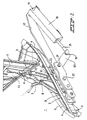
- FIG 1 part of the right rear is not another shown passenger car with trunk. How general known this part of the vehicle body includes a Luggage compartment opening 1, the body being along the Side, and mostly the top, of this trunk opening 1 extending and recessed gutter 2 forms.
- the Gutter has a gutter bottom wall 3 on one side of one Upright outer channel wall 4 is limited.
- the gutter wall 4 connects to an outside of the gutter 2 and higher Exterior wall of the vehicle body, which wall is not shown here is.
- the channel bottom 3 is from one Upright inner channel wall 5, which is limited to one flexible sealing strips extending along its top (not shown) is provided.
- the vehicle also has one Trunk lid 6 for closing the opening 1 of the trunk.
- the trunk lid 6 is about a hinge means in essential horizontal joint axis line articulated on the Vehicle body attached and is movable between its closed stand, in which the trunk lid 6 on the Sealing strip rests on the inner channel wall 5 (so that the Trunk is sealed from the outside atmosphere) and one around an angle to the closed stand upright open Stand (which is shown in Figure 1).
- the hinge means in this example include on each side of the Trunk lid 6 two rods 7, 8, each on their one End via an associated hinge point, or 9, 10 with the vehicle body and at its other end over one associated hinge point, or 11, 12 with one at the Bottom of the trunk lid 6 arranged support 13 articulated are connected.
- these form two Rods 7, 8 with their associated hinge points a so-called Four-bar linkage structure.
- the rods 7, 8 are set up and designed in such a way that these rods in the closed position of the trunk lid 6 lie in the gutter 2.
- the gutter 2 is from above of the part of the Trunk lid 6 covered, but even then the gutter is 2 still in connection with the outside atmosphere.
- the vehicle is for opening and closing the trunk opening 1 further provided with an actuator that here is carried out electrohydraulically.
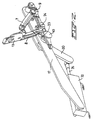
- the electrohydraulic Actuating device includes one not shown electrically driven pump and a collection container for hydraulic fluid a double acting hydraulic Drive cylinder 30 between the vehicle body and the Trunk lid set up to move the trunk lid 6 is.
- the cylinder 30 has a cylinder housing 31 on the bottom side articulated, connected to a support structure 17 by means of pins 16 which is in turn on the inside of the body on the upright gutter wall 4 is attached.
- the cylinder 30 has a reciprocating piston rod 35, via a ball joint coupling 19 with the end of a lever 20 connected is.
- the lever 20 is fixed to one Axis 21 connected, which extends transversely to the lever 20.
- the Axle 21 is at one end through an additional support 22 and sticks in the other direction through the support 17 and then through an opening 23 provided with a sealing ring in the channel wall 4 to the gutter 2.
- the part protruding into the gutter 2 the axis 21 forms the hinge point 10 of the rod 8 and is fixed connected to this rod 8.
- FIG Vehicle body For the sake of clarity, the illustration in FIG Vehicle body omitted. Another is from FIG additional support 24 can be seen in the gutter 2 on the Channel wall 4 is arranged and a solid base for the Points of articulation of the rods 7, 8 creates.
- the support 17 on which the cylinder 30 is supported also forms a Rotary bearing for the axis 21, so that from the cylinder 30 to the Axis 21 applied force is absorbed by the support 17 and does not affect the body.
- the drive cylinder 30 is located in one of the Vehicle body shielded space, instead of in the gutter 2.
- the cylinder 30 and any associated Hoses not resistant to direct exposure To be weather influences, and the weather influences have too less effect on the effect of the hydraulic Actuator.
- Through one of the poles of the itself known four-bar linkage mechanism as part of the transmission between cylinder 15 and the trunk lid to use additional costs will be saved and will also be one of Obtaining an appealing solution. In fact, from the outside are hardly noticed in what way the trunk lid 6th is moved.
- the implementation can be well sealed because water is displaced all over the channel bottom 3 becomes. Furthermore, this list means that there are few problems with the Piles of dirt occur when the transfer medium is in a distance above the channel bottom 3.
- the cylinder 30 is as follows based on the other figures will be explained.
- trunk lid which is here will be almost horizontal in the closed stand, too be applicable to a so-called fifth door of a motor vehicle which fifth door is often almost in its closed position stands vertically.
- present Invention for example also applicable to the car doors and the Hood of a motor vehicle can be. by name Trucks have articulated around a horizontal axis Bonnets with a heavy weight.
- the invention is also applicable when the cover member Folding hood or the like is.
- cover member Folding hood or the like is.
- FIG. 3 shows the double-acting hydraulic cylinder 30 shown.
- the cylinder 30 has a housing 31 with a cylinder space 32, in which a piston 33 with a on the cylindrical wall of the Cylinder chamber 32 sealing ring 34 axially back and forth is mobile.
- a piston rod 35 is fixed to the piston 33 fastened and protrudes through a seal 36 from the housing 31 out.
- the piston / piston rod unit is between the inserted End position and the extended end position movable back and forth.
- the piston 33 distributes the cylinder space 32 into a first chamber 38 and a second chamber 39, each one of the prior art
- the piston / piston rod unit have a dependent volume.
- the housing 31 has one communicating with the chamber 38 Port 40 and a port 41 with the chamber 39 in Connection is established so that hydraulic connections 40, 41 Liquid can be supplied and removed.
- the first chamber 38 is the closing chamber because when hydraulic fluid is supplied to it, the cylinder 30 can deliver a force that leads to the closing movement of the Trunk lid 6 leads.
- the chamber 39 is then the Opening chamber of the cylinder 30.
- the length of this first part is determined by the location of the Cylinder chamber 32 adjoining mouth 42 of a first bypass channel certainly. This mouth 42 is located in the housing Cross bore 43 has been formed.
- the transverse bore 43 is stepped executed so that a seat for the ball 44 is obtained, the is pressed towards the seat by means of the spring 45. This results in a closing in the direction of the cylinder space Check valve in the first bypass channel.
- the transverse bore 47 is on the outside of the housing 31 by means of a plug completed.
- a transverse bore 50 connects the transverse bores 43 and 47 with each other and with the connection 41, so that both bypass channels with the terminal 41 are connected.
- the passage of the part of the transverse bore 43 between the ball 44 and the mouth 42 is smaller than the passage of the part of the Cross bore 47 between the ball 48 and the mouth 46 so that the effective passage of the second bypass channel is smaller than that of first bypass channel.
- the passage of the mouth 42 is significantly smaller than that of the port 40 of the chamber 38, while the passage of the Mouth 46 is almost the same size as that of the connector 40.
- the mouths 42 and 46 between them a second part of the axial Displacement range of the piston / piston rod unit. If at Pushing out the piston rod, the sealing ring 34 passes through the mouth 42 hydraulic fluid can flow out through the first bypass channel the first chamber 38, via the mouth 42 along that of its seat pressed ball 44 and through the transverse bore 50 to the second chamber belonging port 41, and from there to the Collection container of the hydraulic system, not shown stream.
- the area between the mouth 46 and the mouth of the terminal 41 defines a third part of the axial displacement range of the piston / piston rod unit.
- the mouth 46 can be via the mouth 46 of the second bypass channel, along the 48 hydraulic ball pressed from its seat Liquid to the connection 41 belonging to the second chamber 39 and flow from there to the collection container.
- the springs 45 and 49 can be light return springs, whereby the associated balls are pressed directly from their seat when when pushing out the piston rod, the piston such a stand assumes that the associated mouth of the bypass channel is opened.
- the Springs 45 and 49 are designed in such a way that the associated balls can only move from their seat when in the closing chamber 38 exceeds a predetermined pressure level is. This then prevents that already at one low hydraulic pressure in the chamber 38 hydraulic Liquid flows out of the chamber via the bypass channel.
- Figure 4 shows an example of a hydraulic system in which the Cylinder 30 for the application shown in Figures 1 and 2 is arranged.
- FIG 4 is a reversible pump 51 with a suction / Outflow connection 52 and a suction / outflow connection 53 shown. Both connections 52, 53 are in a suction change valve 54 in Connection with a collecting tank 55 for hydraulic Liquid. Pressure relief valves 56 and 57 are also provided Limitation of the maximum hydraulic pressure in the system intended.
- the connections 52 and 53 are respectively to the connections 40 and 41 of the cylinder 30 connected, each in Connection line one of hydraulic fluid flow actuatable valve, or 57 and 58, is arranged.
- These valves 57, 58 are known per se and each include a sliding body that moves back and forth in a hole a central passage channel that is restricted is.
- a connection to the hole then connects each time Collection container 55 on and further a return spring is provided.
- a flow of hydraulic fluid from an outflow connection of the pump to the associated connection pushes the sliding body against the force of the light spring and covers the connection to the container 55.
- one current or in a current in opposite Direction is the connection to the reservoir 55 of this valve 57, 58 just open.
- the cylinder 30 is particularly suitable because of the supply hydraulic fluid to the chamber 38 a closing movement of the Trunk lid 6 with a gradually decreasing from that Cylinder 30 deliverable force is realized.
- the cylinder 30 also delivers a high level in this application Security, as the jamming of an object in the third and possibly second part of the axial runout of the Piston / piston rod unit will play.
- a bypass channel is always open so that the chamber 38 supplied hydraulic fluid can flow out and none undesirably large force can be supplied by the cylinder 30.
- the fuse is not from a valve or other fault-sensitive part.
- this part of the cylinder space could be used a larger diameter, so that hydraulic Pass liquid between the piston and the cylinder wall can.
- Fig. 5 shows a double-acting hydraulic cylinder 60, the effect explained with reference to FIG 3 in a constructively different has been realized wisely.
- the cylinder 60 has a housing 61 with a cylinder space 62 and a back and forth in this displaceable piston 63, which is a first in the cylinder chamber 62 Chamber 65 and a second chamber 66 forms. There is also a connection 67 to the first chamber 65 and a connection to the second chamber 66 seen.
- the piston 63 is provided with a first sealing ring 70, which is designed to seal on the cylindrical wall of the cylinder space 62 to lie on.
- a second sealing ring 71 is also provided, the effect of which will be explained below.
- the sealing ring 70 seals on the wall of the cylinder space 62.
- shallow grooves 72 that extend over a central region of the cylinder space 62 extend, define one adjoining the first part second part of the displacement range of the piston 63.
- the sealing ring 70 seals the shallow grooves 72 not from, so that 72 hydraulic fluid from these grooves the chamber 65 can flow to the chamber 66.
- the seal is 71 such a design that it is capable of the grooves 72 seal, but this acts like a kind of check valve, which in Direction towards chamber 66 to chamber 65 and in in the opposite direction allows the liquid to pass. This is possible, for example, that the sealing ring 71 with a flexible annular lip protruding from the piston is executed.
- the sealing ring 70 seals the Not grooves 73, so that the hydraulic 73 on these grooves Liquid can easily flow from chamber 65 to chamber 66.
- the seal 71 is such a design that it is is able to seal the grooves 73, but this works also like a kind of check valve that closes in the direction to chamber 66 to chamber 65 and the liquid into the other direction.
- Cylinder 60 may suitably be in place of cylinder 30 in Figure 1 can be used, with hydraulic when feeding Liquid to the chamber 65 of the trunk lid 6 a Closing movement executes.
- the grooves 72 which are a kind hydraulic restriction, can automatically when extended realized a reduction in the force available from the cylinder become.
- the piston 63 reaches the deeper grooves 73, the possibly further force to be supplied by the cylinder 60 after, almost to zero. This ensures that the Trunk lid 6 quietly comes on the body and at the same time becomes a safeguard against the use of an impermissibly large force an obstacle that may be in the path of the closing Trunk lid is created.
- Figure 6 shows a modification of the cylinder 30 of Figure 3.
- the in 6 cylinder 80 shown has a housing 81 with a Cylinder chamber 82 and a piston movable back and forth in this 83, a first chamber 85 and a second one in the cylinder chamber 82 Chamber 86 forms. There is also a connection 87 to the first chamber 85 and a connection to the second chamber 86 can be seen.
- the piston 83 is provided with a sealing ring 90 for this purpose is designed to seal on the cylindrical wall of the cylinder space 82 to lie on. Furthermore, two mouths 91 and 92 can be seen, the are connected to terminal 87. This is very similar with the execution of Figure 3, but this is because different that the mouths 91, 92 with the other connection of the Cylinder 80 are connected. For a closing application of a cover, as in FIGS. 1 and 2, this cylinder 80 be set up in such a way that the closing with the incoming stroke of the piston 83 matches. Then it will hydraulic fluid is supplied to the connection 88. Mouths 91, 92 then effect the two-stage reduction in the deliverable Force.
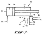
- the double-acting cylinder 100 is shown, which for Example can be applied at the location of the cylinder 30.
- the Cylinder 100 has a housing 101 with a cylinder space in which a Piston 102 one on the cylindrical wall of the cylinder space sealing ring is axially movable back and forth.
- a Piston rod 103 is fixedly attached to the piston 102 and protrudes by a seal out of the housing 101.
- the piston / piston rod unit is between the inserted End position and the extended end position movable back and forth.
- the piston 102 distributes the cylinder space into a first chamber 104 and a second chamber 105, each one of the prior art
- the piston / piston rod unit have a dependent volume.
- Housing 101 has one in communication with chamber 104 standing connection 106 and a connection 107, with the chamber 105 is connected, so that via the connections 106, 107 hydraulic fluid can be supplied and discharged.
- the cylinder 30 In the Application at the location of the cylinder 30 would be the first chamber 104 the lock chamber be there if it's hydraulic fluid is supplied, the cylinder 30 can deliver a force that is used to Closing movement of the trunk lid 6 leads. Chamber 105 is then the opening chamber of the cylinder.
- the length of this first part is determined by the location of the Mouth 108 of a bypass channel 109 adjoining the cylinder space.
- the bypass channel 109 is one in the direction of the Check valve 115 closing cylinder chamber is added.
- the opening port 107 closes over a channel 110 at one Mouth 111 to camera 105.
- a throttle 112 is located in the channel 110 added.
- the bypass channel 109 connects to the channel 110 between the Throttle 112 and the connection 107.
- a circulation channel 113 is provided around throttle 112 around.
- Channel 113 closes on both sides of the choke 112 on the channel 110.
- In channel 113 is an in Check valve 114 closing on port 107 added.
- the cylinder 100 can be advantageously used for driving from a folding top of a passenger car, the Ejecting movement of the piston rod 103 corresponds to that Closing movement of the folding top. Velocity damping prevents the folding top from being too hard on the window post the windshield comes up.
- the solution shown in Figure 7 can also on the other side of the cylinder 100 can be provided.
- this second cylinder can be a standard cylinder without Bypass channels because this second cylinder is then the bypass channels can use in the first cylinder.
Landscapes
- Physics & Mathematics (AREA)
- Fluid Mechanics (AREA)
- Engineering & Computer Science (AREA)
- Mechanical Engineering (AREA)
- General Engineering & Computer Science (AREA)
- Actuator (AREA)
- Forklifts And Lifting Vehicles (AREA)
- Hydraulic Clutches, Magnetic Clutches, Fluid Clutches, And Fluid Joints (AREA)
Claims (14)
- Dispositif d'actionnement hydraulique pour un élément obturateur (6) conçu pour obturer un orifice (1) dans une carrosserie de véhicule, lequel élément obturateur (6) est mobile entre son état fermé, dans lequel ledit élément obturateur (6) obture ledit orifice (1), et un état ouvert, dans lequel le dispositif d'actionnement hydraulique comprend un actionneur hydraulique (30 ; 60 ; 80 ; 100) à double action, destiné à imprimer des mouvements audit élément obturateur (6), lequel actionneur (30 ; 60 ; 80 ; 100) présente un carter (31 ; 61 ; 81 ; 101) muni d'une chambre cylindrique (32) dans laquelle une unité (33, 35 ; 63, 69 ; 83 ; 102, 103) à piston et à tige de piston peut accomplir un va-et-vient, laquelle unité (33, 35 ; 63, 69 ; 83 ; 102, 103) à piston et à tige de piston délimite une chambre de fermeture (38 ; 65 ; 86 ; 104) et une chambre d'ouverture (39 ; 66 ; 85 ; 105) dans la chambre cylindrique, sachant que le carter (31 ; 61 ; 81 ; 101) est pourvu, sur chacune des chambres, d'un raccord associé (40, 41 ; 67, 68 ; 87, 88 ; 106, 107) relié à la chambre cylindrique en vue de la délivrance et de l'évacuation d'un fluide hydraulique ; et sachant que, lors de la délivrance d'un fluide hydraulique à la chambre de fermeture (38 ; 65 ; 86 ; 104), l'actionneur (30 ; 60 ; 80 ; 100) développe une force pour imprimer un mouvement de fermeture à l'élément obturateur (6) vers l'état fermé et développe, lors de la délivrance de fluide à la chambre d'ouverture (39 ; 66 ; 85 ; 105), une force pour imprimer un mouvement d'ouverture audit élément obturateur (6), vers l'état ouvert, le mouvement de fermeture de l'élément obturateur (6), à partir de l'état ouvert, comprenant une première plage et une deuxième plage consécutives, et le dispositif d'actionnement étant agencé de façon telle que la force, pouvant être développée par l'actionneur (30 ; 60 ; 80 ; 100), soit moindre dans la deuxième plage que dans la première plage, caractérisé par le fait que, en vue de diminuer la force précitée, l'actionneur (30 ; 60 ; 80 ; 100) est doté d'un premier canal de dérivation s'étendant entre une première embouchure (42 ; 108) formée dans le carter (31 ; 61 ; 81 ; 101) et se raccordant à la chambre cylindrique (32), et une deuxième embouchure, ladite première embouchure (42 ; 108) étant ménagée de telle sorte que, dans la première plage du mouvement de fermeture, la chambre de fermeture (38 ; 65 ; 86 ; 104) soit uniquement en communication avec le raccord associé (40 ; 67 ; 88 ; 106) et soit obturée par la première embouchure (42 ; 108) du premier canal de dérivation ; et par le fait que, dans la deuxième plage, la chambre de fermeture (38 ; 65 ; 86 ; 104) est reliée à la fois au raccord associé (40 ; 67 ; 88 ; 106), et à la première embouchure (42 ; 108) du premier canal de dérivation, la deuxième embouchure étant agencée de telle sorte que du fluide hydraulique, délivré au raccord (40 ; 67 ; 88 ; 106) de la chambre de fermeture (38 ; 65 ; 86 ; 104), puisse sortir de ladite chambre de fermeture (38 ; 65 ; 86 ; 104) par circulation totale ou partielle le long du premier canal de dérivation.
- Dispositif d'actionnement selon la revendication 1, dans lequel l'actionneur (30 ; 60 ; 80 ; 100) est pourvu d'un second canal de dérivation s'étendant entre des troisième et quatrième embouchures associées ; et dans lequel la troisième embouchure (46 ; 111) est pratiquée dans le carter cylindrique (31 ; 101), se raccorde à la chambre cylindrique (32) et est plus rapprochée du raccord (41 ; 107) de la chambre d'ouverture (39 ; 105) que la première embouchure (42 ; 108) du premier canal de dérivation, si bien que, dans une troisième plage adjacente à la deuxième plage, la chambre de fermeture (38 ; 104) est reliée, à la fois, au raccord associé (40 ; 106) et à la troisième embouchure (46 ; 111) du second canal de dérivation, la quatrième embouchure étant agencée de telle sorte que du fluide hydraulique, délivré au raccord (40 ; 106) de la chambre de fermeture (38 ; 104), puisse sortir de ladite chambre de fermeture (38 ; 104) par circulation totale ou partielle le long du second canal de dérivation.
- Dispositif d'actionnement selon la revendication 2, dans lequel le second canal de dérivation présente un plus grand passage efficace que le premier canal de dérivation.
- Dispositif d'actionnement selon l'une ou plusieurs des revendications précédentes, dans lequel les deuxième et/ou quatrième embouchures sont ménagées dans le carter, et se raccordent à la chambre cylindrique en un emplacement plus rapproché du raccord de la chambre d'ouverture que la première ou troisième embouchure associée, lesquelles deuxième et/ou quatrième embouchures pouvant coïncider avec ledit raccord (41 ; 68 ; 87 ; 107) de ladite chambre d'ouverture (39 ; 66 ; 85 ; 105).
- Dispositif d'actionnement selon l'une ou plusieurs des revendications 1 à 4, dans lequel sont prévus des moyens (44, 45, 48, 49 ; 114, 115 ; 71) à effet de clapet antiretour, qui empêchent un écoulement de fluide hydraulique gagnant la chambre de fermeture (38 ; 104) en empruntant un canal de dérivation.
- Dispositif d'actionnement selon l'une ou plusieurs des revendications précédentes, dans lequel un clapet limiteur de pression (44, 45 ; 48, 49) peut être prévu dans un canal de dérivation, lequel clapet limiteur de pression (44, 45 ; 48, 49) autorise un écoulement de fluide hydraulique, par le canal considéré, lorsque la pression dans la chambre de fermeture (38) excède une valeur préétablie.
- Dispositif d'actionnement selon l'une ou plusieurs des revendications précédentes, dans lequel un canal de dérivation est réalisé sous la forme d'un ou plusieurs évidement(s) (72, 73) pratiqué(s) dans la paroi périphérique de la chambre cylindrique.
- Dispositif d'actionnement selon les revendications 5 et 7, dans lequel une lèvre élastique d'étanchéité (71), relié avec l'unité (69, 70) à piston et à tige de piston, est appliquée de manière étanche contre la paroi périphérique de la chambre cylindrique munie d'un ou plusieurs évidement(s) (72, 73), et est réalisée de façon telle que du fluide hydraulique puisse s'écouler le long de la lèvre d'étanchéité (71) en direction de la chambre de fermeture (65), vers la chambre d'ouverture (66), en interdisant un écoulement de fluide hydraulique dans l'autre direction.
- Dispositif d'actionnement selon la revendication 5, dans lequel un canal de dérivation loge un clapet antiretour qui se ferme en direction de la chambre de fermeture (38), et comprend un siège et un corps obturateur associé (44, 48) poussé en direction dudit siège par un ressort de rappel (45, 49).
- Dispositif d'actionnement selon la revendication 2, dans lequel le second canal de dérivation est réalisé sous la forme d'un ou plusieurs évidement(s) pratiqué(s) dans la paroi périphérique de la chambre cylindrique, et le premier canal de dérivation est réalisé sous la forme d'un canal ménagé dans le carter et se raccordant à la première embouchure.
- Dispositif d'actionnement selon l'une ou plusieurs des revendications précédentes, dans lequel un étranglement (112) est prévu dans un canal (110) situé entre un raccord (107) de l'actionneur (100), et l'embouchure associé (111) pratiqué dans la chambre cylindrique.
- Dispositif d'actionnement selon la revendication 11, dans lequel un canal de contournement (113), prévu tout autour de l'étranglement (112), se raccorde au canal (110) des deux côtés dudit étranglement (112), ledit canal de contournement (113) recevant un clapet antiretour (114) qui se ferme en direction du raccord (107).
- Dispositif d'actionnement selon l'une ou plusieurs des revendications précédentes, dans lequel l'actionneur (30) forme un ensemble unitaire comprenant une pompe (51) pouvant être entraínée électriquement, et un récipient (55) collecteur de fluide hydraulique.
- Dispositif d'actionnement selon l'une ou plusieurs des revendications précédentes, dans lequel un second actionneur, dépourvu de canaux de dérivation, est branché en parallèle avec l'actionneur (30 ; 60 ; 80 ; 100).
Applications Claiming Priority (2)
| Application Number | Priority Date | Filing Date | Title |
|---|---|---|---|
| NL1011362 | 1999-02-22 | ||
| NL1011362A NL1011362C2 (nl) | 1999-02-22 | 1999-02-22 | Hydraulisch bedienbaar afdeksamenstel. |
Publications (2)
| Publication Number | Publication Date |
|---|---|
| EP1031697A1 EP1031697A1 (fr) | 2000-08-30 |
| EP1031697B1 true EP1031697B1 (fr) | 2004-07-14 |
Family
ID=19768702
Family Applications (1)
| Application Number | Title | Priority Date | Filing Date |
|---|---|---|---|
| EP00200603A Expired - Lifetime EP1031697B1 (fr) | 1999-02-22 | 2000-02-21 | Unité d'obturation à commande hydraulique |
Country Status (4)
| Country | Link |
|---|---|
| EP (1) | EP1031697B1 (fr) |
| AT (1) | ATE271181T1 (fr) |
| DE (1) | DE50007032D1 (fr) |
| NL (1) | NL1011362C2 (fr) |
Families Citing this family (10)
| Publication number | Priority date | Publication date | Assignee | Title |
|---|---|---|---|---|
| NL1018501C2 (nl) * | 2001-07-09 | 2003-01-10 | Actuant Corp | Hydraulische bedieningsinrichting. |
| NL1019067C2 (nl) | 2001-10-01 | 2003-04-02 | Actuant Corp | Hydraulische bedieningsinrichting voor een afsluitsamenstel. |
| NL1020960C2 (nl) | 2002-06-28 | 2003-12-30 | Actuant Corp | Hydraulisch bedienbaar afdeksamenstel. |
| DE20219451U1 (de) | 2002-12-13 | 2003-04-24 | TRW Fahrwerksysteme GmbH & Co KG, 40547 Düsseldorf | Hydraulikzylinder |
| DE10305685B4 (de) * | 2003-02-12 | 2005-02-17 | Autoliv Development Ab | Fußgängerschutzeinrichtung an einem Kraftfahrzeug |
| NL1023583C2 (nl) | 2003-06-02 | 2004-12-03 | Actuant Corp | Hydraulische bedieningsinrichting. |
| NL1031072C2 (nl) * | 2006-02-03 | 2007-08-06 | Actuant Corp | Hydraulische bedieningsinrichting. |
| FR2998341B1 (fr) * | 2012-11-16 | 2015-05-15 | Kuhn Sa | Verin a double effet avec un orifice additionnel et machine agricole presentant un tel verin |
| DE102014117054B4 (de) * | 2014-11-21 | 2025-07-10 | Robert Bosch Gmbh | Lenksystem für eine Nachlaufachse eines Fahrzeugs |
| US10006476B2 (en) * | 2015-05-22 | 2018-06-26 | Hamilton Sundstrand Corporation | Mistake proof ram air turbine downlock protection |
Family Cites Families (6)
| Publication number | Priority date | Publication date | Assignee | Title |
|---|---|---|---|---|
| US3138066A (en) * | 1961-10-27 | 1964-06-23 | Phil Wood Ind Ltd | Cushioned-stroke reciprocatory hydraulic motor |
| US5219275A (en) * | 1987-05-21 | 1993-06-15 | Vertran Manufacturing Company | Hydraulic door actuator |
| DE4141820A1 (de) * | 1991-12-18 | 1993-06-24 | Bayerische Motoren Werke Ag | Verstellvorrichtung fuer ein schwenkteil an einem fahrzeug |
| DE4407739C1 (de) | 1994-03-08 | 1995-07-20 | Daimler Benz Ag | Betätigungssystem für über Schaltmittel ansteuerbare hydraulische Antriebselemente eines Klappverdecks |
| AT403785B (de) | 1996-04-24 | 1998-05-25 | Hoerbiger Gmbh | Hydraulische betätigungsanordnung |
| DE19641428C1 (de) | 1996-10-08 | 1998-02-26 | Bayerische Motoren Werke Ag | Einrichtung zum Verschwenken einer klappbaren Haube eines Kraftfahrzeugs, insbesondere eines Gepäckraumdeckels |
-
1999
- 1999-02-22 NL NL1011362A patent/NL1011362C2/nl not_active IP Right Cessation
-
2000
- 2000-02-21 DE DE50007032T patent/DE50007032D1/de not_active Expired - Lifetime
- 2000-02-21 EP EP00200603A patent/EP1031697B1/fr not_active Expired - Lifetime
- 2000-02-21 AT AT00200603T patent/ATE271181T1/de not_active IP Right Cessation
Also Published As
| Publication number | Publication date |
|---|---|
| DE50007032D1 (de) | 2004-08-19 |
| EP1031697A1 (fr) | 2000-08-30 |
| NL1011362C2 (nl) | 2000-08-25 |
| ATE271181T1 (de) | 2004-07-15 |
Similar Documents
| Publication | Publication Date | Title |
|---|---|---|
| DE2400336A1 (de) | Schiffsantriebsvorrichtung | |
| EP0258812B1 (fr) | Dispositif de réglage et blocage continu | |
| EP1031697B1 (fr) | Unité d'obturation à commande hydraulique | |
| EP1101692B1 (fr) | Dispositif de commande hydraulique | |
| EP1407086A1 (fr) | Systeme de commande hydraulique | |
| DE60201055T2 (de) | Hydraulische Betätigungsvorrichtung für eine Schließanordnung | |
| DE4212079C2 (de) | Fluidendruckfeder und Konstruktion mit einer solchen Fluidendruckfeder | |
| EP0937206B1 (fr) | Moteur de positionnement pneumatique ou hydraulique muni d'un dispositif de desenclenchement | |
| DE10100652B4 (de) | Anordnung zur hydraulischen Betätigung eines bewegten Teils an Fahrzeugen | |
| DE10220455B4 (de) | Hydraulische Betätigungsvorrichtung für ein Verdeck mit zugehörigem Riegel | |
| CH684281A5 (de) | Elektrohydraulische Antriebseinheit. | |
| EP0505349B2 (fr) | Vérin hydraulique | |
| EP1293633A2 (fr) | Ferme-porte | |
| EP0893605B1 (fr) | Dispositif de commande hydraulique | |
| DE4216053A1 (de) | Hilfskraftlenkung, insbesondere für Kraftfahrzeuge | |
| DE2050761A1 (de) | Vorrichtung zur Bewegungssteuerung mittels eines hydraulischen Druckzylin ders | |
| DE2003814A1 (de) | Vorrichtung zur Umsetzung einer geradlinigen Bewegung in eine Drehbewegung um eine Schwenkachse | |
| DE19730685A1 (de) | Klappverdeckeinheit für ein Fahrzeug | |
| DE3611710C1 (en) | Reversing device | |
| DE2932298C2 (fr) | ||
| AT406357B (de) | Anordnung zur hydraulischen betätigung eines verdecks, eines heckdeckels od. dgl. | |
| EP0384157B1 (fr) | Soupape à deux voies à commande pilotée hydrauliquement en manière à siège | |
| DE2244445B2 (de) | Hydraulische Einrichtung zum Steuern der Druckmittelwege in einer Anlage mit wenigstens einem doppeltwirkenden Servomotor | |
| DE3022592A1 (de) | Hydraulische steuervorrichtung | |
| DE3007992A1 (de) | Hydraulische drehvorrichtung fuer einen an einen schlepper anhaengbaren drehpflug |
Legal Events
| Date | Code | Title | Description |
|---|---|---|---|
| PUAI | Public reference made under article 153(3) epc to a published international application that has entered the european phase |
Free format text: ORIGINAL CODE: 0009012 |
|
| AK | Designated contracting states |
Kind code of ref document: A1 Designated state(s): AT BE CH CY DE DK ES FI FR GB GR IE IT LI LU MC NL PT SE |
|
| AX | Request for extension of the european patent |
Free format text: AL;LT;LV;MK;RO;SI |
|
| 17P | Request for examination filed |
Effective date: 20001027 |
|
| AKX | Designation fees paid |
Free format text: AT BE CH CY DE DK ES FI FR GB GR IE IT LI LU MC NL PT SE |
|
| RAP1 | Party data changed (applicant data changed or rights of an application transferred) |
Owner name: ACTUANT CORPORATION |
|
| 17Q | First examination report despatched |
Effective date: 20030704 |
|
| GRAP | Despatch of communication of intention to grant a patent |
Free format text: ORIGINAL CODE: EPIDOSNIGR1 |
|
| GRAS | Grant fee paid |
Free format text: ORIGINAL CODE: EPIDOSNIGR3 |
|
| GRAA | (expected) grant |
Free format text: ORIGINAL CODE: 0009210 |
|
| AK | Designated contracting states |
Kind code of ref document: B1 Designated state(s): AT BE CH CY DE DK ES FI FR GB GR IE IT LI LU MC NL PT SE |
|
| PG25 | Lapsed in a contracting state [announced via postgrant information from national office to epo] |
Ref country code: FI Free format text: LAPSE BECAUSE OF FAILURE TO SUBMIT A TRANSLATION OF THE DESCRIPTION OR TO PAY THE FEE WITHIN THE PRESCRIBED TIME-LIMIT Effective date: 20040714 Ref country code: IE Free format text: LAPSE BECAUSE OF FAILURE TO SUBMIT A TRANSLATION OF THE DESCRIPTION OR TO PAY THE FEE WITHIN THE PRESCRIBED TIME-LIMIT Effective date: 20040714 Ref country code: NL Free format text: LAPSE BECAUSE OF FAILURE TO SUBMIT A TRANSLATION OF THE DESCRIPTION OR TO PAY THE FEE WITHIN THE PRESCRIBED TIME-LIMIT Effective date: 20040714 Ref country code: GB Free format text: LAPSE BECAUSE OF FAILURE TO SUBMIT A TRANSLATION OF THE DESCRIPTION OR TO PAY THE FEE WITHIN THE PRESCRIBED TIME-LIMIT Effective date: 20040714 |
|
| REG | Reference to a national code |
Ref country code: GB Ref legal event code: FG4D Free format text: NOT ENGLISH |
|
| REG | Reference to a national code |
Ref country code: CH Ref legal event code: EP |
|
| REF | Corresponds to: |
Ref document number: 50007032 Country of ref document: DE Date of ref document: 20040819 Kind code of ref document: P |
|
| REG | Reference to a national code |
Ref country code: IE Ref legal event code: FG4D Free format text: GERMAN |
|
| PG25 | Lapsed in a contracting state [announced via postgrant information from national office to epo] |
Ref country code: GR Free format text: LAPSE BECAUSE OF FAILURE TO SUBMIT A TRANSLATION OF THE DESCRIPTION OR TO PAY THE FEE WITHIN THE PRESCRIBED TIME-LIMIT Effective date: 20041014 Ref country code: DK Free format text: LAPSE BECAUSE OF FAILURE TO SUBMIT A TRANSLATION OF THE DESCRIPTION OR TO PAY THE FEE WITHIN THE PRESCRIBED TIME-LIMIT Effective date: 20041014 |
|
| PG25 | Lapsed in a contracting state [announced via postgrant information from national office to epo] |
Ref country code: ES Free format text: LAPSE BECAUSE OF FAILURE TO SUBMIT A TRANSLATION OF THE DESCRIPTION OR TO PAY THE FEE WITHIN THE PRESCRIBED TIME-LIMIT Effective date: 20041025 |
|
| REG | Reference to a national code |
Ref country code: SE Ref legal event code: TRGR |
|
| NLV1 | Nl: lapsed or annulled due to failure to fulfill the requirements of art. 29p and 29m of the patents act | ||
| GBV | Gb: ep patent (uk) treated as always having been void in accordance with gb section 77(7)/1977 [no translation filed] |
Effective date: 20040714 |
|
| ET | Fr: translation filed | ||
| PG25 | Lapsed in a contracting state [announced via postgrant information from national office to epo] |
Ref country code: AT Free format text: LAPSE BECAUSE OF NON-PAYMENT OF DUE FEES Effective date: 20050221 Ref country code: CY Free format text: LAPSE BECAUSE OF FAILURE TO SUBMIT A TRANSLATION OF THE DESCRIPTION OR TO PAY THE FEE WITHIN THE PRESCRIBED TIME-LIMIT Effective date: 20050221 Ref country code: LU Free format text: LAPSE BECAUSE OF NON-PAYMENT OF DUE FEES Effective date: 20050221 |
|
| PG25 | Lapsed in a contracting state [announced via postgrant information from national office to epo] |
Ref country code: LI Free format text: LAPSE BECAUSE OF NON-PAYMENT OF DUE FEES Effective date: 20050228 Ref country code: CH Free format text: LAPSE BECAUSE OF NON-PAYMENT OF DUE FEES Effective date: 20050228 Ref country code: MC Free format text: LAPSE BECAUSE OF NON-PAYMENT OF DUE FEES Effective date: 20050228 Ref country code: BE Free format text: LAPSE BECAUSE OF NON-PAYMENT OF DUE FEES Effective date: 20050228 |
|
| REG | Reference to a national code |
Ref country code: IE Ref legal event code: FD4D |
|
| PLBE | No opposition filed within time limit |
Free format text: ORIGINAL CODE: 0009261 |
|
| STAA | Information on the status of an ep patent application or granted ep patent |
Free format text: STATUS: NO OPPOSITION FILED WITHIN TIME LIMIT |
|
| 26N | No opposition filed |
Effective date: 20050415 |
|
| BERE | Be: lapsed |
Owner name: *ACTUANT CORP. Effective date: 20050228 |
|
| REG | Reference to a national code |
Ref country code: CH Ref legal event code: PL |
|
| BERE | Be: lapsed |
Owner name: *ACTUANT CORP. Effective date: 20050228 |
|
| PG25 | Lapsed in a contracting state [announced via postgrant information from national office to epo] |
Ref country code: PT Free format text: LAPSE BECAUSE OF NON-PAYMENT OF DUE FEES Effective date: 20041214 |
|
| PGFP | Annual fee paid to national office [announced via postgrant information from national office to epo] |
Ref country code: SE Payment date: 20140227 Year of fee payment: 15 Ref country code: DE Payment date: 20140227 Year of fee payment: 15 |
|
| PGFP | Annual fee paid to national office [announced via postgrant information from national office to epo] |
Ref country code: FR Payment date: 20140220 Year of fee payment: 15 Ref country code: IT Payment date: 20140226 Year of fee payment: 15 |
|
| REG | Reference to a national code |
Ref country code: DE Ref legal event code: R119 Ref document number: 50007032 Country of ref document: DE |
|
| REG | Reference to a national code |
Ref country code: SE Ref legal event code: EUG |
|
| REG | Reference to a national code |
Ref country code: FR Ref legal event code: ST Effective date: 20151030 |
|
| PG25 | Lapsed in a contracting state [announced via postgrant information from national office to epo] |
Ref country code: SE Free format text: LAPSE BECAUSE OF NON-PAYMENT OF DUE FEES Effective date: 20150222 |
|
| PG25 | Lapsed in a contracting state [announced via postgrant information from national office to epo] |
Ref country code: IT Free format text: LAPSE BECAUSE OF NON-PAYMENT OF DUE FEES Effective date: 20150221 |
|
| PG25 | Lapsed in a contracting state [announced via postgrant information from national office to epo] |
Ref country code: DE Free format text: LAPSE BECAUSE OF NON-PAYMENT OF DUE FEES Effective date: 20150901 |
|
| PG25 | Lapsed in a contracting state [announced via postgrant information from national office to epo] |
Ref country code: FR Free format text: LAPSE BECAUSE OF NON-PAYMENT OF DUE FEES Effective date: 20150302 |