EP1031741B1 - Senkkopfschraube - Google Patents
Senkkopfschraube Download PDFInfo
- Publication number
- EP1031741B1 EP1031741B1 EP00102216A EP00102216A EP1031741B1 EP 1031741 B1 EP1031741 B1 EP 1031741B1 EP 00102216 A EP00102216 A EP 00102216A EP 00102216 A EP00102216 A EP 00102216A EP 1031741 B1 EP1031741 B1 EP 1031741B1
- Authority
- EP
- European Patent Office
- Prior art keywords
- fins
- screw according
- countersunk head
- head screw
- contact surface
- Prior art date
- Legal status (The legal status is an assumption and is not a legal conclusion. Google has not performed a legal analysis and makes no representation as to the accuracy of the status listed.)
- Expired - Lifetime
Links
- 239000000463 material Substances 0.000 claims description 18
- 230000004323 axial length Effects 0.000 claims description 14
- 230000000694 effects Effects 0.000 claims description 14
- 239000002184 metal Substances 0.000 claims description 3
- 230000037431 insertion Effects 0.000 claims 1
- 238000003780 insertion Methods 0.000 claims 1
- 238000003801 milling Methods 0.000 description 20
- 230000006378 damage Effects 0.000 description 2
- 230000003247 decreasing effect Effects 0.000 description 1
- 230000000149 penetrating effect Effects 0.000 description 1
- 238000007790 scraping Methods 0.000 description 1
- 238000009987 spinning Methods 0.000 description 1
Images
Classifications
-
- F—MECHANICAL ENGINEERING; LIGHTING; HEATING; WEAPONS; BLASTING
- F16—ENGINEERING ELEMENTS AND UNITS; GENERAL MEASURES FOR PRODUCING AND MAINTAINING EFFECTIVE FUNCTIONING OF MACHINES OR INSTALLATIONS; THERMAL INSULATION IN GENERAL
- F16B—DEVICES FOR FASTENING OR SECURING CONSTRUCTIONAL ELEMENTS OR MACHINE PARTS TOGETHER, e.g. NAILS, BOLTS, CIRCLIPS, CLAMPS, CLIPS OR WEDGES; JOINTS OR JOINTING
- F16B35/00—Screw-bolts; Stay-bolts; Screw-threaded studs; Screws; Set screws
- F16B35/04—Screw-bolts; Stay-bolts; Screw-threaded studs; Screws; Set screws with specially-shaped head or shaft in order to fix the bolt on or in an object
- F16B35/06—Specially-shaped heads
- F16B35/065—Specially-shaped heads with self-countersink-cutting means
Definitions
- the invention relates to a countersunk screw with a head, with a shaft and with an at least partially extending thread, the Head at least in sections tapering towards the shaft Has contact surface, wherein in an upper, the shaft facing away from the Support surface ribs are arranged.
- Countersunk screws can be used, for example, in the head of a drive recess, such as a Slotted or cross-slotted to attack a screwdriver.
- the free shaft end can be designed as a tip.
- it can be Countersunk screws acting on the material into which they are screwed have a thread-forming or thread-cutting effect.
- EP 0 705 987 A1 describes a countersunk screw of the generic type described, which carries ribs in the upper area facing away from the shaft.
- the Ribs have a cutting-like triangular shape, which means that they cut Effect of the ribs on a material. Due to the cutting effect The ribs have a braking effect when the ribs with the material in Come into contact.
- the invention is based on the object of a countersunk screw Generic type to improve such that the aforementioned negative Apparitions can be avoided.
- the ribs are designed as brake ribs in this way are that when they are screwed into a material, such as a metal surface Fitting, due to an increased surface pressure between the head and the material increase the frictional resistance, with a cutting effect both when entering and is largely excluded even when unscrewing.
- the brake ribs cause when screwing in an inventive Countersunk screw an increased surface pressure between the screw and the Material into which it is screwed, for example on the metal surface of a Fitting. This increases the frictional resistance and acts on the torque against the screwdriver, which causes the screw to spin can be prevented.
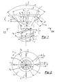
- FIG. 1 shows a first embodiment of an inventive Countersunk screw a head 1, a shaft 2 and an at least partially extending over the shaft 2 Thread 3 on.
- the head 1 in turn has one at least in sections in the direction of the shaft 2 tapered support surface 4. In an upper, Area 5 of the support surface 4 facing away from the shaft 2 Brake ribs 6 arranged.
- brake ribs 6 In the embodiment shown there are four brake ribs 6 provided, but it could also be more or less, e.g. two, three or six.
- the conical bearing surface in the direction of the shaft 2 4 converges in a first, facing away from the shaft 2 Head section 5a at an angle ⁇ of approximately 90 ° and in a second head section facing the shaft 2 5b at an angle ⁇ of approximately 50 ° to 65 °.
- ⁇ of approximately 90 °
- ⁇ of approximately 50 ° to 65 °.
- the area 5 of the support surface 4, in which the brake ribs 6 are arranged, is not greater in terms of its axial length H B than about 60 percent of an axial length H A of the conically tapering support surface 4.
- the brake ribs 6 advantageously only act after the countersunk screw according to the invention is almost completely screwed in. This prevents the screw from spinning, and threads that are shaped or cut in the material can be protected.
- the brake ribs 6 can - as shown - extend with respect to their longitudinal extension L R on generatrices of the bearing surface 4, the projection P of which falls on a section of the screw longitudinal axis XX of the screw according to the invention extending through the head 1. In this way, the surface pressure between the screw and the material-increasing effect of the brake ribs 6 is particularly large.
- the thread 3 has a thread edge 7, which runs in a main area in the form of a screw line at a constant distance (outer radius A of the thread 3) to a section of the screw longitudinal axis XX running through the shaft 2.
- the thread edge 7 can have a decreasing height H K in an end region 8 of the thread 3 facing the head 1.
- the brake ribs 6 can extend in an optimal arrangement with regard to their coming into effect - seen in the bottom view or in the sectional view shown in FIG. 2 - in a ring area which on the outside approximately by an outer radius R K of the head 1 and on the inside approximately by the The outer radius A of the thread 3 is.
- the brake ribs 6 have a variable height H RB over their longitudinal extent L R.
- the height H RB of the brake ribs 6 extends in an arcuate manner over the longitudinal extension L R of the brake ribs 6 from a value of zero relative to the support surface 4 and in turn ends at a value of zero relative to the support surface 4.
- the maximum value of the height H RB of the brake ribs 6 relative to the contact surface 4 can advantageously be approximately 0.1 to 0.2 mm, in particular with an outer radius R K of the head 1 of approximately 4 to 5 mm.
- the brake ribs 6 can - as shown - two each Side surfaces 6a, 6b of convex shape, in particular the Form of a discussion segment.
- the side surfaces 6a, 6b adjoin a central one in particular Edge 6c to each other.
- this will in particular achieved a high frictional resistance when screwing in, a cutting effect of the brake ribs both when entering and also when unscrewing a screw according to the invention however largely excluded.
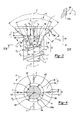
- This embodiment differs not with respect to the brake ribs 6 of the described first execution.
- the Area 105 of the support surface 4 facing the shaft 2 however, additional milling ribs 106 are arranged. These milling ribs 106 effect when screwing in an inventive Countersunk screw takes away material, which also means a countersunk screw whose head is larger than the norm accordingly an undesirable material destruction effective can be prevented.
- milling ribs 106 there are six milling ribs 106 provided, but it could also be more or less, e.g. three, four, eight or more. By the number and training the milling ribs 106 allows the desired removal of material when screwing in a countersunk screw according to the invention increase or decrease and thus to the material to adjust.
- the milling ribs 106 extend into a region 2a of the shaft 2 close to the head, where the shaft 2 has a radius R S that is greater than a core radius R E of the shaft 2 in the region 2b of the thread 3. In the region 2a close to the head the milling ribs 106 are each connected to the shaft 2, which ensures high mechanical stability of the milling ribs 106.
- the area 105 of the bearing surface 4, in which the milling ribs 106 are arranged is not greater than approximately 60 percent of an axial length H A of the conically tapering bearing surface 4 with regard to its axial length H F.
- there is an axial length H T in the area 2a close to the head which can be about one third of the axial length H F in the bearing surface 4 lying area 105.
- the milling ribs 106 thus advantageously only act when the head 1 of the countersunk screw according to the invention begins to penetrate the material. This prevents material destruction in the sense of splintering, tearing or undesired deformation.
- the milling ribs 106 can - as shown - run with respect to their longitudinal extent L F on generatrices of the bearing surface 4, the projection of which falls on a section of the screw longitudinal axis XX of the screw according to the invention extending through the head 1. In this way, the milling or scraping effect which the milling ribs 106 exert on the material is particularly great.
- the milling ribs 106 can extend in an optimal arrangement with regard to their coming into effect - seen in the bottom view or in the sectional view shown in FIG. 2 - in a ring region which on the outside approximately by the outer radius A of the thread 3 and on the inside approximately by the outer radius R S of the shaft 2 is limited in the area 2a close to the head.
- the milling ribs 106 have a variable height H RF over their longitudinal extent L F.
- the height H RF of the milling ribs 106 rises above the longitudinal extent L F of the milling ribs 106 on the outside, starting from a value of zero relative to the bearing surface 4, and then runs approximately constant relative to the bearing surface 4. This achieves a uniform milling effect over the longitudinal extent L F of the milling ribs 106.
- the maximum value of the height H RF of the milling ribs 106 relative to the contact surface 4 can advantageously be about 0.3 mm, in particular with an outer radius R K of the head 1 of about 4 to 5 mm.
- the cutting ribs 106 have an optimal shape, if - as the drawing illustrates - each in have the shape of a segment of a circle, an edge 106a of the Circular segment is flat or concave.
- the invention is not limited to the exemplary embodiments described, but also encompasses all embodiments having the same effect in the sense of the invention.
- the number, shape and arrangement of the brake ribs 6 can deviate from the embodiment described. So it may be appropriate that the brake ribs 6 do not - as shown - run with respect to their longitudinal extension L R on generatrices of the bearing surface 4, the projection P of which falls on a section of the screw longitudinal axis XX of the screw according to the invention running through the head 1, but ( similar to the thread 3) lie on an at least partially circumferential circumferential helical path.
Landscapes
- Engineering & Computer Science (AREA)
- General Engineering & Computer Science (AREA)
- Mechanical Engineering (AREA)
- Connection Of Plates (AREA)
- Surgical Instruments (AREA)
- Milling Processes (AREA)
- Shafts, Cranks, Connecting Bars, And Related Bearings (AREA)
Applications Claiming Priority (2)
| Application Number | Priority Date | Filing Date | Title |
|---|---|---|---|
| DE29903231U | 1999-02-23 | ||
| DE29903231U DE29903231U1 (de) | 1999-02-23 | 1999-02-23 | Senkkopfschraube |
Publications (2)
| Publication Number | Publication Date |
|---|---|
| EP1031741A1 EP1031741A1 (de) | 2000-08-30 |
| EP1031741B1 true EP1031741B1 (de) | 2004-01-07 |
Family
ID=8069819
Family Applications (1)
| Application Number | Title | Priority Date | Filing Date |
|---|---|---|---|
| EP00102216A Expired - Lifetime EP1031741B1 (de) | 1999-02-23 | 2000-02-10 | Senkkopfschraube |
Country Status (8)
| Country | Link |
|---|---|
| US (1) | US6394725B1 (cs) |
| EP (1) | EP1031741B1 (cs) |
| CN (1) | CN1188610C (cs) |
| CA (1) | CA2299795C (cs) |
| CZ (1) | CZ293884B6 (cs) |
| DE (2) | DE29903231U1 (cs) |
| ES (1) | ES2211387T3 (cs) |
| PL (1) | PL192314B1 (cs) |
Families Citing this family (44)
| Publication number | Priority date | Publication date | Assignee | Title |
|---|---|---|---|---|
| DE29906200U1 (de) * | 1999-04-07 | 2000-09-07 | A-Z Ausrüstung und Zubehör GmbH & Co. KG, 45525 Hattingen | Senkkopfschraube |
| US6908270B1 (en) * | 1999-07-12 | 2005-06-21 | Iwata Bolt Kabushiki Kaisha | Self-locking bolt |
| DE10243791A1 (de) * | 2002-09-17 | 2004-03-18 | Schäfer, Bernd | Halswirbelplatte |
| US7160303B2 (en) * | 2003-01-23 | 2007-01-09 | Cervitech, Inc. | Medical implant with a secured bone screw |
| US20050013680A1 (en) * | 2003-07-18 | 2005-01-20 | Steve Karaga | Screws and methods of driving a screw into a workpiece |
| DE20313819U1 (de) * | 2003-09-05 | 2005-01-13 | A-Z Ausrüstung Und Zubehör Gmbh & Co. Kg | Senkkopfschraube |
| US20050081578A1 (en) * | 2003-10-17 | 2005-04-21 | Yoon Jong S. | Screw assembly and washing machine using the same |
| US7014406B2 (en) * | 2004-01-07 | 2006-03-21 | Newfrey Llc | Anti-strip-out fastener |
| US7329077B2 (en) | 2004-07-01 | 2008-02-12 | Curtis David A W | Fastener apparatus for roofing and steel building construction |
| CA2476046C (en) * | 2004-07-23 | 2012-07-10 | Bruce Mead | Grounding method and grid for a pedestal supported access floor |
| DE102006002559A1 (de) * | 2006-01-10 | 2007-07-12 | Swg Schraubenwerk Gaisbach Gmbh | Senkkopfschraube |
| DE102008000550A1 (de) * | 2008-03-06 | 2009-09-10 | Hilti Aktiengesellschaft | Schraube |
| CA2647663C (en) * | 2008-12-19 | 2013-08-20 | Mirco Walther | Self-counter-sinking screw with circumferential cutters |
| GB2470404B (en) * | 2009-05-22 | 2014-03-19 | Phillips Screw Co | Low energy screws for wood and similar materials |
| US20110064540A1 (en) * | 2009-09-17 | 2011-03-17 | Mirco Walther | Screw having underside cutters and pockets |
| JP5364045B2 (ja) * | 2010-06-11 | 2013-12-11 | 川崎重工業株式会社 | 油圧機器用埋め栓 |
| US20130022426A1 (en) * | 2011-07-19 | 2013-01-24 | Yih Shwei Bolt Industrial Co., Ltd. | Screw |
| US8905697B2 (en) * | 2012-04-23 | 2014-12-09 | Illinois Tool Works Inc. | Thermal break fastener |
| US9695860B2 (en) | 2012-10-09 | 2017-07-04 | Handy & Harman | Wood decking screw |
| US20150063947A1 (en) * | 2013-08-29 | 2015-03-05 | Shu-Chin Huang | Screw capable of easily drilling holes and dregs removing |
| US10626909B2 (en) * | 2013-08-29 | 2020-04-21 | Shu-Chin Huang | Countersinking screw capable of easily drilling holes and dregs removing |
| US20150094777A1 (en) * | 2013-10-02 | 2015-04-02 | Exsomed Holding Company Llc | Bone screw |
| WO2015050895A1 (en) | 2013-10-02 | 2015-04-09 | Exsomed Holding Company Llc | Full wrist fusion device |
| CN104564978A (zh) * | 2013-10-09 | 2015-04-29 | 英业达科技有限公司 | 锁固组件及其沉头螺丝 |
| KR200477278Y1 (ko) * | 2013-11-28 | 2015-05-26 | 새한전자(주) | 목재 체결용 나사 |
| US11033353B2 (en) * | 2014-09-15 | 2021-06-15 | Spinal Developments Pty Ltd, A.T.F. The Spinesr Unit Trust | Fiducial marker |
| EP3002468A1 (en) * | 2014-10-02 | 2016-04-06 | Schencho Industrial Co., Ltd | Self-drilling screw |
| US9581183B2 (en) | 2015-02-17 | 2017-02-28 | The Hillman Group, Inc. | Screw-type fastener |
| TW201632744A (zh) * | 2015-03-11 | 2016-09-16 | 寬仕工業股份有限公司 | 防裂及防起毛邊之螺絲 |
| WO2016186847A1 (en) | 2015-05-19 | 2016-11-24 | Exsomed International IP, LLC | Distal radius plate |
| US11147604B2 (en) | 2016-01-12 | 2021-10-19 | ExsoMed Corporation | Bone stabilization device |
| US10436238B2 (en) | 2016-04-04 | 2019-10-08 | The Hillman Group, Inc. | Screw type fastener |
| SG11202001648XA (en) | 2017-09-05 | 2020-03-30 | Exsomed Corp | Intramedullary threaded nail for radial cortical fixation |
| DK179847B1 (en) * | 2017-11-01 | 2019-07-31 | Dissing A/S | Screw with tapered screw-head, use of a screw and a method for countersinking the screw |
| US11105361B2 (en) | 2017-11-03 | 2021-08-31 | The Hillman Group, Inc. | Screw-type fastener |
| US10480562B2 (en) * | 2017-12-19 | 2019-11-19 | Bi-Mirth Corp. | Self-tapping screw head structure |
| CN111936279A (zh) | 2018-04-09 | 2020-11-13 | 希尔曼集团股份有限公司 | 用于混凝土和抗飓风应用的螺旋式紧固件 |
| CN110792670A (zh) * | 2018-08-03 | 2020-02-14 | 庆达科技股份有限公司 | 锁固件 |
| US12313108B2 (en) | 2020-02-11 | 2025-05-27 | B.M.B. Investments Pty Ltd | Multipurpose screw |
| US12473942B2 (en) | 2021-03-30 | 2025-11-18 | The Hillman Group, Inc. | Wood screw |
| US12085107B2 (en) | 2021-03-30 | 2024-09-10 | The Hillman Group, Inc. | Structural screw |
| USD1106810S1 (en) | 2022-09-29 | 2025-12-23 | The Hillman Group, Inc. | Screw |
| USD1115507S1 (en) | 2023-06-02 | 2026-03-03 | The Hillman Group, Inc. | Screw |
| USD1116789S1 (en) | 2023-06-02 | 2026-03-10 | The Hillman Group, Inc. | Screw |
Family Cites Families (13)
| Publication number | Priority date | Publication date | Assignee | Title |
|---|---|---|---|---|
| US1175665A (en) * | 1915-09-29 | 1916-03-14 | William Russell Sweet | Wood-screw. |
| GB113183A (en) * | 1917-04-10 | 1918-02-14 | Henry Collins | Improvements in Wood Screws. |
| US2037586A (en) * | 1934-06-27 | 1936-04-14 | Illinois Tool Works | Locking means for threaded elements |
| US3903784A (en) * | 1972-01-03 | 1975-09-09 | Anchor Bolt And Screw Company | Self-countersinking fastener head |
| EP0102605B1 (de) * | 1982-09-02 | 1986-08-13 | Rockenfeller KG Befestigungselemente | Holzschraube |
| JPH0571521A (ja) * | 1991-05-29 | 1993-03-23 | Toopura:Kk | ドリリングねじ |
| JPH0571520A (ja) * | 1991-05-29 | 1993-03-23 | Toopura:Kk | ドリリングねじ |
| US5516248A (en) * | 1994-09-07 | 1996-05-14 | Abbott-Interfast Corporation | Low torque wood screw |
| FR2725252B1 (fr) * | 1994-10-04 | 1996-12-27 | Vynex Sa | Vis a tete fraisee auto-foreuse |
| DE29508852U1 (de) * | 1995-05-29 | 1996-09-26 | EJOT Verbindungstechnik GmbH & Co. KG, 57334 Bad Laasphe | Senkkopfschraube |
| DE29600065U1 (de) * | 1996-01-03 | 1996-03-28 | Yu, Chao-Hsin, Taipeh/T'ai-pei | Senkkopfschraube |
| US5683217A (en) * | 1996-03-27 | 1997-11-04 | Walther; Uli | Self-counter-sinking screw with cutting receiving pockets |
| DE29811536U1 (de) * | 1998-06-29 | 1998-10-01 | Bierbach GmbH & Co. KG Befestigungstechnik, 59425 Unna | Schraube für Holzwerkstoffe |
-
1999
- 1999-02-23 DE DE29903231U patent/DE29903231U1/de not_active Expired - Lifetime
-
2000
- 2000-02-10 ES ES00102216T patent/ES2211387T3/es not_active Expired - Lifetime
- 2000-02-10 EP EP00102216A patent/EP1031741B1/de not_active Expired - Lifetime
- 2000-02-10 DE DE50004955T patent/DE50004955D1/de not_active Expired - Lifetime
- 2000-02-16 CZ CZ2000542A patent/CZ293884B6/cs not_active IP Right Cessation
- 2000-02-23 PL PL338572A patent/PL192314B1/pl unknown
- 2000-02-23 CN CNB00102633XA patent/CN1188610C/zh not_active Expired - Fee Related
- 2000-02-23 CA CA002299795A patent/CA2299795C/en not_active Expired - Fee Related
- 2000-02-23 US US09/511,050 patent/US6394725B1/en not_active Expired - Lifetime
Also Published As
| Publication number | Publication date |
|---|---|
| CN1188610C (zh) | 2005-02-09 |
| CZ293884B6 (cs) | 2004-08-18 |
| DE50004955D1 (de) | 2004-02-12 |
| CN1264796A (zh) | 2000-08-30 |
| EP1031741A1 (de) | 2000-08-30 |
| PL192314B1 (pl) | 2006-09-29 |
| CA2299795A1 (en) | 2000-08-23 |
| CA2299795C (en) | 2007-12-18 |
| ES2211387T3 (es) | 2004-07-16 |
| US6394725B1 (en) | 2002-05-28 |
| PL338572A1 (en) | 2000-08-28 |
| DE29903231U1 (de) | 2000-07-06 |
| HK1030254A1 (en) | 2001-04-27 |
| CZ2000542A3 (en) | 2001-05-16 |
Similar Documents
| Publication | Publication Date | Title |
|---|---|---|
| EP1031741B1 (de) | Senkkopfschraube | |
| EP1031742B1 (de) | Senkkopfschraube | |
| DE69905783T2 (de) | Schraube für Fasermaterial | |
| EP1165972B1 (de) | Selbstbohrendes und gewindeformendes verbindungselement | |
| DE69304631T2 (de) | Selbstbohrende schraube | |
| DE4307090B4 (de) | Mutter, insbesondere Radmutter | |
| EP1512876B1 (de) | Senkkopfschraube | |
| DE3610392C2 (de) | Schraube für verunreinigte Gewindebohrungen | |
| DE60216489T2 (de) | Schneidwerkzeug | |
| EP0939235B1 (de) | Schraube | |
| EP1165974B1 (de) | Senkkopfschraube | |
| WO2005080802A1 (de) | Gewindeformende schraube | |
| DE2047482A1 (de) | Gewindebildende Schraube | |
| EP1129297B1 (de) | Korrosionsfeste schraube mit schneideinsatz | |
| EP2806174A1 (de) | Schraubelement | |
| DE69607462T2 (de) | Selbstsichernde Mutter | |
| EP3401557B2 (de) | Holzschraube | |
| EP0141235B1 (de) | Schlitzschraube | |
| DE69013340T2 (de) | Bohrschraube mit zur Kopfseite gekrümmten Schneiden. | |
| EP0589398B1 (de) | Selbstfurchende Schraube | |
| DE20102269U1 (de) | Senkschraube | |
| DE69902723T2 (de) | Ein Schneideinsatz | |
| DE29711128U1 (de) | Selbstbohrendes und gewindeformendes Verbindungselement | |
| EP3404273A1 (de) | Schraubelement | |
| EP1574727B1 (de) | Selbstfurchende Schraube |
Legal Events
| Date | Code | Title | Description |
|---|---|---|---|
| PUAI | Public reference made under article 153(3) epc to a published international application that has entered the european phase |
Free format text: ORIGINAL CODE: 0009012 |
|
| 17P | Request for examination filed |
Effective date: 20000603 |
|
| AK | Designated contracting states |
Kind code of ref document: A1 Designated state(s): DE ES FR GB IT |
|
| AX | Request for extension of the european patent |
Free format text: AL;LT;LV;MK;RO;SI |
|
| AKX | Designation fees paid |
Free format text: DE ES FR GB IT |
|
| 17Q | First examination report despatched |
Effective date: 20020211 |
|
| GRAP | Despatch of communication of intention to grant a patent |
Free format text: ORIGINAL CODE: EPIDOSNIGR1 |
|
| GRAS | Grant fee paid |
Free format text: ORIGINAL CODE: EPIDOSNIGR3 |
|
| GRAA | (expected) grant |
Free format text: ORIGINAL CODE: 0009210 |
|
| AK | Designated contracting states |
Kind code of ref document: B1 Designated state(s): DE ES FR GB IT |
|
| REG | Reference to a national code |
Ref country code: GB Ref legal event code: FG4D Free format text: NOT ENGLISH |
|
| REF | Corresponds to: |
Ref document number: 50004955 Country of ref document: DE Date of ref document: 20040212 Kind code of ref document: P |
|
| GBT | Gb: translation of ep patent filed (gb section 77(6)(a)/1977) |
Effective date: 20040511 |
|
| REG | Reference to a national code |
Ref country code: ES Ref legal event code: FG2A Ref document number: 2211387 Country of ref document: ES Kind code of ref document: T3 |
|
| ET | Fr: translation filed | ||
| PLBE | No opposition filed within time limit |
Free format text: ORIGINAL CODE: 0009261 |
|
| STAA | Information on the status of an ep patent application or granted ep patent |
Free format text: STATUS: NO OPPOSITION FILED WITHIN TIME LIMIT |
|
| 26N | No opposition filed |
Effective date: 20041008 |
|
| REG | Reference to a national code |
Ref country code: FR Ref legal event code: PLFP Year of fee payment: 17 |
|
| REG | Reference to a national code |
Ref country code: DE Ref legal event code: R082 Ref document number: 50004955 Country of ref document: DE Representative=s name: PATENTANWAELTE BECKER & MUELLER, DE Ref country code: DE Ref legal event code: R082 Ref document number: 50004955 Country of ref document: DE Representative=s name: PATENT- UND RECHTSANWAELTE DR. SOLF & ZAPF, DE Ref country code: DE Ref legal event code: R081 Ref document number: 50004955 Country of ref document: DE Owner name: SPAX INTERNATIONAL GMBH & CO. KG, DE Free format text: FORMER OWNER: A-Z AUSRUESTUNG UND ZUBEHOER GMBH & CO. KG, 45525 HATTINGEN, DE |
|
| REG | Reference to a national code |
Ref country code: FR Ref legal event code: PLFP Year of fee payment: 18 |
|
| REG | Reference to a national code |
Ref country code: FR Ref legal event code: PLFP Year of fee payment: 19 |
|
| REG | Reference to a national code |
Ref country code: DE Ref legal event code: R082 Ref document number: 50004955 Country of ref document: DE Representative=s name: PATENTANWAELTE BECKER & MUELLER, DE |
|
| REG | Reference to a national code |
Ref country code: FR Ref legal event code: TP Owner name: SPAX INTERNATIONAL GMBH & CO.KG, DE Effective date: 20180706 |
|
| REG | Reference to a national code |
Ref country code: ES Ref legal event code: PC2A Owner name: SPAX INTERNATIONAL GMBH & CO. KG Effective date: 20180918 Ref country code: ES Ref legal event code: PC2A Effective date: 20180918 |
|
| REG | Reference to a national code |
Ref country code: GB Ref legal event code: 732E Free format text: REGISTERED BETWEEN 20181108 AND 20181114 |
|
| PGFP | Annual fee paid to national office [announced via postgrant information from national office to epo] |
Ref country code: GB Payment date: 20190128 Year of fee payment: 20 Ref country code: ES Payment date: 20190301 Year of fee payment: 20 Ref country code: DE Payment date: 20190214 Year of fee payment: 20 Ref country code: IT Payment date: 20190222 Year of fee payment: 20 |
|
| PGFP | Annual fee paid to national office [announced via postgrant information from national office to epo] |
Ref country code: FR Payment date: 20190221 Year of fee payment: 20 |
|
| REG | Reference to a national code |
Ref country code: DE Ref legal event code: R071 Ref document number: 50004955 Country of ref document: DE |
|
| REG | Reference to a national code |
Ref country code: GB Ref legal event code: PE20 Expiry date: 20200209 |
|
| PG25 | Lapsed in a contracting state [announced via postgrant information from national office to epo] |
Ref country code: GB Free format text: LAPSE BECAUSE OF EXPIRATION OF PROTECTION Effective date: 20200209 |
|
| REG | Reference to a national code |
Ref country code: ES Ref legal event code: FD2A Effective date: 20200902 |
|
| PG25 | Lapsed in a contracting state [announced via postgrant information from national office to epo] |
Ref country code: ES Free format text: LAPSE BECAUSE OF EXPIRATION OF PROTECTION Effective date: 20200211 |