EP1031805B1 - Klimatisierungselement - Google Patents
Klimatisierungselement Download PDFInfo
- Publication number
- EP1031805B1 EP1031805B1 EP00890049A EP00890049A EP1031805B1 EP 1031805 B1 EP1031805 B1 EP 1031805B1 EP 00890049 A EP00890049 A EP 00890049A EP 00890049 A EP00890049 A EP 00890049A EP 1031805 B1 EP1031805 B1 EP 1031805B1
- Authority
- EP
- European Patent Office
- Prior art keywords
- pipe
- flow pipe
- flow
- carrier medium
- distributing
- Prior art date
- Legal status (The legal status is an assumption and is not a legal conclusion. Google has not performed a legal analysis and makes no representation as to the accuracy of the status listed.)
- Expired - Lifetime
Links
- 238000004378 air conditioning Methods 0.000 title claims abstract description 20
- 230000001154 acute effect Effects 0.000 claims abstract description 3
- WYTGDNHDOZPMIW-RCBQFDQVSA-N alstonine Natural products C1=CC2=C3C=CC=CC3=NC2=C2N1C[C@H]1[C@H](C)OC=C(C(=O)OC)[C@H]1C2 WYTGDNHDOZPMIW-RCBQFDQVSA-N 0.000 claims description 3
- 238000010992 reflux Methods 0.000 claims 10
- 238000010438 heat treatment Methods 0.000 description 4
- 239000012530 fluid Substances 0.000 description 2
- 238000004519 manufacturing process Methods 0.000 description 2
- 239000002184 metal Substances 0.000 description 2
- 229910052751 metal Inorganic materials 0.000 description 2
- 238000000034 method Methods 0.000 description 2
- RYGMFSIKBFXOCR-UHFFFAOYSA-N Copper Chemical compound [Cu] RYGMFSIKBFXOCR-UHFFFAOYSA-N 0.000 description 1
- 229910000831 Steel Inorganic materials 0.000 description 1
- 230000015572 biosynthetic process Effects 0.000 description 1
- 238000001816 cooling Methods 0.000 description 1
- 229910052802 copper Inorganic materials 0.000 description 1
- 239000010949 copper Substances 0.000 description 1
- 230000001747 exhibiting effect Effects 0.000 description 1
- 238000001125 extrusion Methods 0.000 description 1
- 239000011505 plaster Substances 0.000 description 1
- 239000004033 plastic Substances 0.000 description 1
- 239000003507 refrigerant Substances 0.000 description 1
- 239000010959 steel Substances 0.000 description 1
- XLYOFNOQVPJJNP-UHFFFAOYSA-N water Substances O XLYOFNOQVPJJNP-UHFFFAOYSA-N 0.000 description 1
Images

Classifications
-
- F—MECHANICAL ENGINEERING; LIGHTING; HEATING; WEAPONS; BLASTING
- F28—HEAT EXCHANGE IN GENERAL
- F28F—DETAILS OF HEAT-EXCHANGE AND HEAT-TRANSFER APPARATUS, OF GENERAL APPLICATION
- F28F9/00—Casings; Header boxes; Auxiliary supports for elements; Auxiliary members within casings
- F28F9/02—Header boxes; End plates
- F28F9/026—Header boxes; End plates with static flow control means, e.g. with means for uniformly distributing heat exchange media into conduits
- F28F9/027—Header boxes; End plates with static flow control means, e.g. with means for uniformly distributing heat exchange media into conduits in the form of distribution pipes
- F28F9/0275—Header boxes; End plates with static flow control means, e.g. with means for uniformly distributing heat exchange media into conduits in the form of distribution pipes with multiple branch pipes
-
- F—MECHANICAL ENGINEERING; LIGHTING; HEATING; WEAPONS; BLASTING
- F28—HEAT EXCHANGE IN GENERAL
- F28D—HEAT-EXCHANGE APPARATUS, NOT PROVIDED FOR IN ANOTHER SUBCLASS, IN WHICH THE HEAT-EXCHANGE MEDIA DO NOT COME INTO DIRECT CONTACT
- F28D1/00—Heat-exchange apparatus having stationary conduit assemblies for one heat-exchange medium only, the media being in contact with different sides of the conduit wall, in which the other heat-exchange medium is a large body of fluid, e.g. domestic or motor car radiators
- F28D1/02—Heat-exchange apparatus having stationary conduit assemblies for one heat-exchange medium only, the media being in contact with different sides of the conduit wall, in which the other heat-exchange medium is a large body of fluid, e.g. domestic or motor car radiators with heat-exchange conduits immersed in the body of fluid
- F28D1/04—Heat-exchange apparatus having stationary conduit assemblies for one heat-exchange medium only, the media being in contact with different sides of the conduit wall, in which the other heat-exchange medium is a large body of fluid, e.g. domestic or motor car radiators with heat-exchange conduits immersed in the body of fluid with tubular conduits
-
- F—MECHANICAL ENGINEERING; LIGHTING; HEATING; WEAPONS; BLASTING
- F28—HEAT EXCHANGE IN GENERAL
- F28F—DETAILS OF HEAT-EXCHANGE AND HEAT-TRANSFER APPARATUS, OF GENERAL APPLICATION
- F28F1/00—Tubular elements; Assemblies of tubular elements
- F28F1/006—Tubular elements; Assemblies of tubular elements with variable shape, e.g. with modified tube ends, with different geometrical features
Definitions
- the invention relates to an air-conditioning element through which a carrier medium flows according to the preamble of claim 1.
- Air conditioning elements of this type are known in a variety of variations, e.g. out AT 401 294 B.
- the carrier medium for example hot water over a Feed into the flow pipe, from which it flows to the confluence of the one smaller cross-section than the flow pipe having manifolds flows.
- the carrier medium dissipates the heat, and the carrier medium flows through the distributor tubes the confluence areas in the serving as a manifold return pipe, which again has a larger cross section than the distribution pipes.
- the return pipe is thus Carrier medium collected and fed via a drain of a heat source in which it is heated again to flow through the air conditioning element again.
- Air conditioning elements of this type are when used for space heating as well Heating register designated and can be used as underfloor heating in screed or wall heating or used as wall cooling embedded in the wall plaster, as this For example, in AT 401 294 B is described.
- a refrigerant distributor which is a transversely to his Longitudinal extrusion has extruded metal profile, at the side channels, by pipes are formed, are connected.
- the extruded metal profile that forms the main channel has arcuately shaped, directed against the flow direction mouth pieces, into which the rectilinear tubes open.
- FR 918.616 A is an air conditioning element according to the preamble of Claim 1, in which tubes of a tube exchanger are curved at their ends, so that its end direction is approximately the same as that of the direction of flow when the fluid enters the pipes and the discharge of the fluid from the pipes without significant change in direction he follows.
- the invention has as its object, an air conditioning element according to the preamble of claim 1, but to provide increased performance, which also improved Having flow conditions for the carrier medium.
- Air conditioning element at a variety of distribution pipes aerodynamically cheaper be than conventional air conditioning elements. This is how eddies of the Carrier medium can be reduced or largely avoided and the Total flow resistance of the air conditioning element can be reduced.
- This object is achieved in that the distribution pipes between the Lead pipe and the return pipe serpentine and steadily in the Overflow confluence areas.
- an air conditioning element in which an inlet and a process for a carrier medium is connected directly to distribution pipes.
- the Distributor pipes open into a narrower cross section than the cross section of a Distributor tube exhibiting connector, wherein this connector in turn further distribution pipes are connected.
- arcuate designed Pipe ends provided tangentially in the flow direction of the support medium open into one another.
- a particularly easy to manufacture variant is characterized in that in the Junction of a manifold in the flow pipe or optionally in the Return pipe the longitudinal axis of the manifold is rectilinear.
- the longitudinal axis the manifold is arcuate.
- a further improvement of the flow for the carrier medium can be achieved thereby that in the junction region of a manifold in the flow pipe or optionally in the return pipe a resulting acute-angled wall portion below Extension of the interior is capped at the junction area.
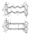
- FIG. 2 shows a schematic illustration of an air-conditioning element according to the invention, from FIG Seeing the page, illustrate.
- Figs. 3, 4 and 5 are different Embodiments of the junction areas of the distribution pipes in the return pipe in Section shown.
- With 1 is a to an unspecified inlet for a carrier medium connected flow pipe referred to, from the distribution pipes 2, which has a smaller Have cross-section than the flow pipe, go out and in a distance from Flow pipe 1 arranged return pipe 3 open.
- the return pipe 3 is at a End connected in a conventional manner to a process for the carrier medium, but what is not illustrated in detail.
- the distributor pipes are 2 - of which are shown for clarity, only two of several - in the Junction areas 4, both in the flow pipe 1 and in the return pipe 3, arched, u.zw. such that the carrier medium, which by the arrows 5 is illustrated, if possible without vortex formation from the flow pipe 1 in the distribution pipes. 2 and from these in turn flows into the return pipe 3.
- arcuate junctions of the distribution pipes 2 in the flow pipe 1 and in the return pipe 3 are the angles ⁇ by tangents 7, which are at the center axes of the Supply pipes are placed at these junction areas 4, illustrated.
- an air conditioning element shown in Fig. 2 are the Distributor tubes 2 serpentine between the flow pipe 1 and the return pipe. 3 arranged, whereby a greater length of the same at the same distance of Flow pipe 1 from the return pipe 3 results. This allows for the same area a achieve higher performance.
- junction areas 4 of the distribution pipes shown in FIG 2 in the return pipe 3 are the distributor pipes 2 at the ends, i. in the immediate Area of connection to the return pipe 3, designed rectilinear, resulting in yield manufacturing advantages.
- Fig. 4 shows in Fig. 3 analog representation of a Enlargement of the interior space at the confluence areas 4, which is achieved by that the acute-angled wall part 8 (shown in FIG. 3) between the distributor pipes 2 and the return pipe 3 is processed.
- Fig. 5 the mouth areas 4 of manifolds, as shown in Figs. 1 and 2 are shown schematically, illustrated on an enlarged scale.
- the flow and the return pipe 1, 3, a variety of cross sections, such. circular, oval, rectangular, have.
- the cross sections of the distribution pipes freely selectable according to the desired conditions.
- the air conditioning element may be off Be made of copper, plastic or steel; it can also use multilayer pipes Find.
Landscapes
- Engineering & Computer Science (AREA)
- Physics & Mathematics (AREA)
- Thermal Sciences (AREA)
- Mechanical Engineering (AREA)
- General Engineering & Computer Science (AREA)
- Geometry (AREA)
- Duct Arrangements (AREA)
- Branch Pipes, Bends, And The Like (AREA)
- Air-Conditioning For Vehicles (AREA)
- Glass Compositions (AREA)
- Surgical Instruments (AREA)
Description
Claims (4)
- Von einem Trägermedium (5) durchflossenes Klimatisierungselement mit einem Vorlaufrohr (1), einem Rücklaufrohr (3) sowie einer Anzahl von diese beiden Rohre (1, 3) miteinander verbindenden Verteilerrohren (2) mit geringerem Querschnitt als das Vorlaufrohr (1) und das Rücklaufrohr (3), wobei das Vorlaufrohr (1) an einen Zulauf für das Trägermedium und das Rücklaufrohr (3) an einen Ablauf für das Trägermedium (5) anschließbar sind und die Achsen der Verteilerrohre (2) in den Einmündungsbereichen (4) in das Vorlaufrohr (1) und vorzugsweise auch in das Rücklaufrohr (3) mit der Längsachse (6) des Vorlaufrohres (1) sowie vorzugsweise auch mit der Längsachse (6) des Rücklaufrohres (3) jeweils einen spitzen Winkel (α) einschließen, der mit der Strömungsrichtung des Trägermediums (5) im Vorlaufrohr (1) divergiert und mit der Strömungsrichtung des Trägermediums (5) im Rücklaufrohr (3) konvergiert, dadurch gekennzeichnet, daß die Verteilerrohre (2) zwischen dem Vorlaufrohr (1) und dem Rücklaufrohr (3) schlangenförmig verlaufen und stetig in die Einmündungsbereiche (4) übergehen.
- Klimatisierungselement nach Anspruch 1, dadurch gekennzeichnet, daß in dem Einmündungsbereich (4) eines Verteilerrohres (2) in das Vorlaufrohr (1) bzw. gegebenenfalls in das Rücklaufrohr (3) die Längsachse des Verteilerrohres (2) geradlinig verläuft (Fig. 3, 4).
- Klimatisierungselement nach Anspruch 1, dadurch gekennzeichnet, daß in dem Einmündungsbereich (4) eines Verteilerrohres (2) in das Vorlaufrohr (1) bzw. gegebenenfalls in das Rücklaufrohr (3) die Längsachse des Verteilerrohres (2) bogenförmig ausgebildet ist (Fig. 1, 2, 5).
- Klimatisierungselement nach einem oder mehreren der Ansprüche 1 bis 3, dadurch gekennzeichnet, daß in dem Einmündungsbereich (4) eines Verteilerrohres (2) in das Vorlaufrohr (1) bzw. gegebenenfalls in das Rücklaufrohr (3) ein sich ergebender spitzwinkeliger Wandteil (8) unter Erweiterung des Innenraumes bei dem Einmündungsbereich (4) gekappt ist.
Priority Applications (1)
| Application Number | Priority Date | Filing Date | Title |
|---|---|---|---|
| SI200030818T SI1031805T1 (sl) | 1999-02-22 | 2000-02-21 | Element za klimatiziranje |
Applications Claiming Priority (2)
| Application Number | Priority Date | Filing Date | Title |
|---|---|---|---|
| AT29399 | 1999-02-22 | ||
| AT0029399A AT407668B (de) | 1999-02-22 | 1999-02-22 | Klimatisierungselement |
Publications (3)
| Publication Number | Publication Date |
|---|---|
| EP1031805A2 EP1031805A2 (de) | 2000-08-30 |
| EP1031805A3 EP1031805A3 (de) | 2001-05-23 |
| EP1031805B1 true EP1031805B1 (de) | 2005-12-14 |
Family
ID=3486709
Family Applications (1)
| Application Number | Title | Priority Date | Filing Date |
|---|---|---|---|
| EP00890049A Expired - Lifetime EP1031805B1 (de) | 1999-02-22 | 2000-02-21 | Klimatisierungselement |
Country Status (4)
| Country | Link |
|---|---|
| EP (1) | EP1031805B1 (de) |
| AT (2) | AT407668B (de) |
| DE (1) | DE50011838D1 (de) |
| SI (1) | SI1031805T1 (de) |
Families Citing this family (4)
| Publication number | Priority date | Publication date | Assignee | Title |
|---|---|---|---|---|
| AT412669B (de) * | 2003-02-27 | 2005-05-25 | Raimund Harreither | Als wandelement gestaltetes klimatisierungselement |
| US9689594B2 (en) * | 2012-07-09 | 2017-06-27 | Modine Manufacturing Company | Evaporator, and method of conditioning air |
| US20150060034A1 (en) * | 2013-08-30 | 2015-03-05 | Uop Llc | Heat transfer unit for process fluids |
| CN110595111B (zh) * | 2019-06-28 | 2021-11-02 | 杭州三花微通道换热器有限公司 | 换热器和多制冷系统空调机组 |
Family Cites Families (9)
| Publication number | Priority date | Publication date | Assignee | Title |
|---|---|---|---|---|
| FR563768A (fr) * | 1922-06-24 | 1923-12-13 | Perfectionnements aux radiateurs | |
| FR918616A (fr) * | 1945-08-27 | 1947-02-13 | Système de guidage de fluide pour échangeur de température | |
| FR2496864A3 (fr) * | 1980-12-24 | 1982-06-25 | Sueddeutsche Kuehler Behr | Echangeur de chaleur destine en particulier a l'installation de chauffage ou de climatisation d'un vehicule |
| DE4102700C2 (de) * | 1991-01-30 | 2002-02-07 | Detlef Zimmer | Mit einer Elastomer-Ummantelung versehener Schlauchverbinder in Form eines Verbindungs-, Winkel-, T-Stückes o. dgl. |
| DE4319192A1 (de) * | 1993-06-09 | 1994-12-15 | Behr Gmbh & Co | Verfahren zur Herstellung von Kältemittelverteilern, insbesondere für Verdampfer einer Klimaanlage eines Kraftfahrzeuges |
| AT401294B (de) * | 1993-06-18 | 1996-07-25 | Harreither Gmbh | Von einem trägermedium durchflossenes klimatisierungselement |
| KR100223086B1 (ko) * | 1994-09-16 | 1999-10-15 | 다카노 야스아키 | 열교환기를 탑재한 냉각장치 |
| JPH1038206A (ja) * | 1996-07-25 | 1998-02-13 | Mitsubishi Heavy Ind Ltd | 中間管寄せ |
| DE19743427B4 (de) * | 1997-10-01 | 2007-05-03 | Behr Gmbh & Co. Kg | Wärmeübertrager |
-
1999
- 1999-02-22 AT AT0029399A patent/AT407668B/de not_active IP Right Cessation
-
2000
- 2000-02-21 AT AT00890049T patent/ATE313054T1/de active
- 2000-02-21 EP EP00890049A patent/EP1031805B1/de not_active Expired - Lifetime
- 2000-02-21 SI SI200030818T patent/SI1031805T1/sl unknown
- 2000-02-21 DE DE50011838T patent/DE50011838D1/de not_active Expired - Lifetime
Also Published As
| Publication number | Publication date |
|---|---|
| AT407668B (de) | 2001-05-25 |
| DE50011838D1 (de) | 2006-01-19 |
| EP1031805A3 (de) | 2001-05-23 |
| SI1031805T1 (sl) | 2006-06-30 |
| ATE313054T1 (de) | 2005-12-15 |
| EP1031805A2 (de) | 2000-08-30 |
| ATA29399A (de) | 2000-09-15 |
Similar Documents
| Publication | Publication Date | Title |
|---|---|---|
| DE20321667U1 (de) | Flüssigkeitserhitzer | |
| AT406505B (de) | Verteileranordnung | |
| DE69900133T2 (de) | Gas-Flüssigkeitswärmetauscher und Verfahren zu dessen Herstellung | |
| DE102012005513A1 (de) | Wärmetauscher, Verfahren zu seiner Herstellung sowie verschiedene Anlagen mit einem derartigen Wärmetauscher | |
| DE102006018688B4 (de) | Verfahren zum Biegen von Multiportrohren für Wärmeübertrager | |
| AT407668B (de) | Klimatisierungselement | |
| WO2010111998A2 (de) | Abwasserrohr mit einer frischwasserleiteinrichtung sowie wärmeübertrager | |
| DE10134619A1 (de) | Wärmetauscher für ein Gasheizgerät, insbesondere ein Brennwertgerät | |
| EP1668304B1 (de) | Wärmetauschereinheit für kraftfahrzeuge | |
| DE102010028117A1 (de) | Verbindungselement für Röhrenwärmetauscher | |
| WO2017102154A1 (de) | Vorrichtung zur verbindung zumindest einer armatur und einer leitung mit thermischer entkopplung | |
| EP1314947A2 (de) | Wärmetauscher, insbesondere für Heizungsanlagen | |
| AT401294B (de) | Von einem trägermedium durchflossenes klimatisierungselement | |
| DE19832051C2 (de) | Heiz- bzw. Kühlkörper-Verteileranordnung | |
| DE102010028867B4 (de) | Heizkörper für eine Klimaanlage | |
| EP2253493B1 (de) | Vorrichtung zur Beheizung des Innenraumes eines Kraftfahrzeuges | |
| DE202008001611U1 (de) | Vorrichtung zur solaren Energiegewinnung, insbesondere Solarkollektor | |
| DE10341644B4 (de) | Wendelförmiger Wärmeaustauscher | |
| DE202019103964U1 (de) | Wärmeaustauscher | |
| DE10134271B4 (de) | Rohrprofil für biegsame Leitungen mit ovalen Querschnitt | |
| EP2144029A1 (de) | Wärmeübertrager insbesondere eines Kraftfahrzeuges zum Kühlen eines Kältemittels und Verfahren zum Kühlen eines Kältemittels | |
| DE4208675A1 (de) | Elektrischer durchlauferhitzer | |
| DE10062481A1 (de) | Solaranlage | |
| EP1348914B1 (de) | Wärmetauscher, Verbrennungsvorrichtung, einen Wärmetauscher umfassend, Absperrelement zur Verwendung in einem solchen Wärmetauscher, und Verfahren zur Herstellung eines Wärmetauschers | |
| DE1991281U (de) | Axialsammler und -verteiler an Vielfachverzweigungen von Wärmeübertragern |
Legal Events
| Date | Code | Title | Description |
|---|---|---|---|
| PUAI | Public reference made under article 153(3) epc to a published international application that has entered the european phase |
Free format text: ORIGINAL CODE: 0009012 |
|
| AK | Designated contracting states |
Kind code of ref document: A2 Designated state(s): AT BE CH CY DE DK ES FI FR GB GR IE IT LI LU MC NL PT SE |
|
| AX | Request for extension of the european patent |
Free format text: AL;LT;LV;MK;RO;SI |
|
| PUAL | Search report despatched |
Free format text: ORIGINAL CODE: 0009013 |
|
| AK | Designated contracting states |
Kind code of ref document: A3 Designated state(s): AT BE CH CY DE DK ES FI FR GB GR IE IT LI LU MC NL PT SE |
|
| AX | Request for extension of the european patent |
Free format text: AL;LT;LV;MK;RO;SI |
|
| 17P | Request for examination filed |
Effective date: 20011016 |
|
| AKX | Designation fees paid |
Free format text: AT BE CH CY DE DK ES FI FR GB GR IE IT LI LU MC NL PT SE |
|
| AXX | Extension fees paid |
Free format text: SI PAYMENT 20011016 |
|
| 17Q | First examination report despatched |
Effective date: 20030901 |
|
| GRAP | Despatch of communication of intention to grant a patent |
Free format text: ORIGINAL CODE: EPIDOSNIGR1 |
|
| GRAS | Grant fee paid |
Free format text: ORIGINAL CODE: EPIDOSNIGR3 |
|
| GRAA | (expected) grant |
Free format text: ORIGINAL CODE: 0009210 |
|
| AK | Designated contracting states |
Kind code of ref document: B1 Designated state(s): AT BE CH CY DE DK ES FI FR GB GR IE IT LI LU MC NL PT SE |
|
| AX | Request for extension of the european patent |
Extension state: SI |
|
| PG25 | Lapsed in a contracting state [announced via postgrant information from national office to epo] |
Ref country code: FI Free format text: LAPSE BECAUSE OF FAILURE TO SUBMIT A TRANSLATION OF THE DESCRIPTION OR TO PAY THE FEE WITHIN THE PRESCRIBED TIME-LIMIT Effective date: 20051214 Ref country code: IE Free format text: LAPSE BECAUSE OF FAILURE TO SUBMIT A TRANSLATION OF THE DESCRIPTION OR TO PAY THE FEE WITHIN THE PRESCRIBED TIME-LIMIT Effective date: 20051214 Ref country code: GB Free format text: LAPSE BECAUSE OF FAILURE TO SUBMIT A TRANSLATION OF THE DESCRIPTION OR TO PAY THE FEE WITHIN THE PRESCRIBED TIME-LIMIT Effective date: 20051214 |
|
| REG | Reference to a national code |
Ref country code: GB Ref legal event code: FG4D Free format text: NOT ENGLISH |
|
| REG | Reference to a national code |
Ref country code: CH Ref legal event code: EP |
|
| REG | Reference to a national code |
Ref country code: IE Ref legal event code: FG4D Free format text: LANGUAGE OF EP DOCUMENT: GERMAN |
|
| REF | Corresponds to: |
Ref document number: 50011838 Country of ref document: DE Date of ref document: 20060119 Kind code of ref document: P |
|
| PG25 | Lapsed in a contracting state [announced via postgrant information from national office to epo] |
Ref country code: MC Free format text: LAPSE BECAUSE OF NON-PAYMENT OF DUE FEES Effective date: 20060228 |
|
| PG25 | Lapsed in a contracting state [announced via postgrant information from national office to epo] |
Ref country code: SE Free format text: LAPSE BECAUSE OF FAILURE TO SUBMIT A TRANSLATION OF THE DESCRIPTION OR TO PAY THE FEE WITHIN THE PRESCRIBED TIME-LIMIT Effective date: 20060314 Ref country code: DK Free format text: LAPSE BECAUSE OF FAILURE TO SUBMIT A TRANSLATION OF THE DESCRIPTION OR TO PAY THE FEE WITHIN THE PRESCRIBED TIME-LIMIT Effective date: 20060314 |
|
| PG25 | Lapsed in a contracting state [announced via postgrant information from national office to epo] |
Ref country code: ES Free format text: LAPSE BECAUSE OF FAILURE TO SUBMIT A TRANSLATION OF THE DESCRIPTION OR TO PAY THE FEE WITHIN THE PRESCRIBED TIME-LIMIT Effective date: 20060325 |
|
| REG | Reference to a national code |
Ref country code: CH Ref legal event code: NV Representative=s name: SCHMAUDER & PARTNER AG PATENTANWALTSBUERO |
|
| REG | Reference to a national code |
Ref country code: GR Ref legal event code: EP Ref document number: 20060400781 Country of ref document: GR |
|
| PG25 | Lapsed in a contracting state [announced via postgrant information from national office to epo] |
Ref country code: PT Free format text: LAPSE BECAUSE OF FAILURE TO SUBMIT A TRANSLATION OF THE DESCRIPTION OR TO PAY THE FEE WITHIN THE PRESCRIBED TIME-LIMIT Effective date: 20060515 |
|
| GBV | Gb: ep patent (uk) treated as always having been void in accordance with gb section 77(7)/1977 [no translation filed] |
Effective date: 20051214 |
|
| REG | Reference to a national code |
Ref country code: IE Ref legal event code: FD4D |
|
| PLBE | No opposition filed within time limit |
Free format text: ORIGINAL CODE: 0009261 |
|
| STAA | Information on the status of an ep patent application or granted ep patent |
Free format text: STATUS: NO OPPOSITION FILED WITHIN TIME LIMIT |
|
| 26N | No opposition filed |
Effective date: 20060915 |
|
| EN | Fr: translation not filed | ||
| PG25 | Lapsed in a contracting state [announced via postgrant information from national office to epo] |
Ref country code: FR Free format text: LAPSE BECAUSE OF FAILURE TO SUBMIT A TRANSLATION OF THE DESCRIPTION OR TO PAY THE FEE WITHIN THE PRESCRIBED TIME-LIMIT Effective date: 20070202 |
|
| PG25 | Lapsed in a contracting state [announced via postgrant information from national office to epo] |
Ref country code: FR Free format text: LAPSE BECAUSE OF FAILURE TO SUBMIT A TRANSLATION OF THE DESCRIPTION OR TO PAY THE FEE WITHIN THE PRESCRIBED TIME-LIMIT Effective date: 20060228 |
|
| PG25 | Lapsed in a contracting state [announced via postgrant information from national office to epo] |
Ref country code: FR Free format text: LAPSE BECAUSE OF FAILURE TO SUBMIT A TRANSLATION OF THE DESCRIPTION OR TO PAY THE FEE WITHIN THE PRESCRIBED TIME-LIMIT Effective date: 20051214 |
|
| REG | Reference to a national code |
Ref country code: CH Ref legal event code: PCAR Free format text: SCHMAUDER & PARTNER AG PATENT- UND MARKENANWAELTE VSP;ZWAENGIWEG 7;8038 ZUERICH (CH) |
|
| PGFP | Annual fee paid to national office [announced via postgrant information from national office to epo] |
Ref country code: NL Payment date: 20180216 Year of fee payment: 19 Ref country code: LU Payment date: 20180216 Year of fee payment: 19 |
|
| PGFP | Annual fee paid to national office [announced via postgrant information from national office to epo] |
Ref country code: BE Payment date: 20180216 Year of fee payment: 19 Ref country code: GR Payment date: 20180213 Year of fee payment: 19 |
|
| PGFP | Annual fee paid to national office [announced via postgrant information from national office to epo] |
Ref country code: CY Payment date: 20180212 Year of fee payment: 19 |
|
| PGFP | Annual fee paid to national office [announced via postgrant information from national office to epo] |
Ref country code: DE Payment date: 20190219 Year of fee payment: 20 Ref country code: CH Payment date: 20190221 Year of fee payment: 20 Ref country code: IT Payment date: 20190222 Year of fee payment: 20 |
|
| PGFP | Annual fee paid to national office [announced via postgrant information from national office to epo] |
Ref country code: AT Payment date: 20190220 Year of fee payment: 20 |
|
| REG | Reference to a national code |
Ref country code: NL Ref legal event code: MM Effective date: 20190301 |
|
| PG25 | Lapsed in a contracting state [announced via postgrant information from national office to epo] |
Ref country code: CY Free format text: LAPSE BECAUSE OF NON-PAYMENT OF DUE FEES Effective date: 20190221 Ref country code: LU Free format text: LAPSE BECAUSE OF NON-PAYMENT OF DUE FEES Effective date: 20190221 |
|
| REG | Reference to a national code |
Ref country code: BE Ref legal event code: MM Effective date: 20190228 |
|
| PG25 | Lapsed in a contracting state [announced via postgrant information from national office to epo] |
Ref country code: GR Free format text: LAPSE BECAUSE OF NON-PAYMENT OF DUE FEES Effective date: 20190904 |
|
| PG25 | Lapsed in a contracting state [announced via postgrant information from national office to epo] |
Ref country code: NL Free format text: LAPSE BECAUSE OF NON-PAYMENT OF DUE FEES Effective date: 20190301 |
|
| REG | Reference to a national code |
Ref country code: DE Ref legal event code: R071 Ref document number: 50011838 Country of ref document: DE |
|
| PG25 | Lapsed in a contracting state [announced via postgrant information from national office to epo] |
Ref country code: BE Free format text: LAPSE BECAUSE OF NON-PAYMENT OF DUE FEES Effective date: 20190228 |
|
| REG | Reference to a national code |
Ref country code: CH Ref legal event code: PL |
|
| REG | Reference to a national code |
Ref country code: AT Ref legal event code: MK07 Ref document number: 313054 Country of ref document: AT Kind code of ref document: T Effective date: 20200221 |