EP1031845B1 - Procédé de calibrage pour un récepteur de type GLONASS - Google Patents
Procédé de calibrage pour un récepteur de type GLONASS Download PDFInfo
- Publication number
- EP1031845B1 EP1031845B1 EP00102857A EP00102857A EP1031845B1 EP 1031845 B1 EP1031845 B1 EP 1031845B1 EP 00102857 A EP00102857 A EP 00102857A EP 00102857 A EP00102857 A EP 00102857A EP 1031845 B1 EP1031845 B1 EP 1031845B1
- Authority
- EP
- European Patent Office
- Prior art keywords
- signals
- receiver
- carrier phase
- channel
- frequency
- Prior art date
- Legal status (The legal status is an assumption and is not a legal conclusion. Google has not performed a legal analysis and makes no representation as to the accuracy of the status listed.)
- Expired - Lifetime
Links
- 238000000034 method Methods 0.000 title claims abstract description 16
- 238000005259 measurement Methods 0.000 claims abstract description 67
- 238000012545 processing Methods 0.000 claims description 30
- 238000001914 filtration Methods 0.000 claims description 9
- 238000001228 spectrum Methods 0.000 claims description 8
- 238000003860 storage Methods 0.000 claims description 8
- 230000000694 effects Effects 0.000 claims description 6
- 210000000352 storage cell Anatomy 0.000 claims description 4
- 239000006227 byproduct Substances 0.000 claims description 2
- 238000005070 sampling Methods 0.000 abstract description 9
- 230000000875 corresponding effect Effects 0.000 description 7
- 238000013461 design Methods 0.000 description 7
- 230000032683 aging Effects 0.000 description 6
- 238000012937 correction Methods 0.000 description 6
- 230000001934 delay Effects 0.000 description 6
- 238000010586 diagram Methods 0.000 description 4
- 230000008569 process Effects 0.000 description 4
- 230000006870 function Effects 0.000 description 3
- 230000035945 sensitivity Effects 0.000 description 3
- 238000000926 separation method Methods 0.000 description 3
- 238000013459 approach Methods 0.000 description 2
- 230000002596 correlated effect Effects 0.000 description 2
- 238000004519 manufacturing process Methods 0.000 description 2
- 239000000047 product Substances 0.000 description 2
- 238000010897 surface acoustic wave method Methods 0.000 description 2
- 239000000919 ceramic Substances 0.000 description 1
- 229910010293 ceramic material Inorganic materials 0.000 description 1
- 230000001427 coherent effect Effects 0.000 description 1
- 239000002131 composite material Substances 0.000 description 1
- 230000001419 dependent effect Effects 0.000 description 1
- 238000001514 detection method Methods 0.000 description 1
- 230000007613 environmental effect Effects 0.000 description 1
- 239000005433 ionosphere Substances 0.000 description 1
- 230000000737 periodic effect Effects 0.000 description 1
- 230000003595 spectral effect Effects 0.000 description 1
- 230000007480 spreading Effects 0.000 description 1
- 238000003892 spreading Methods 0.000 description 1
- 230000001360 synchronised effect Effects 0.000 description 1
Images


Classifications
-
- G—PHYSICS
- G01—MEASURING; TESTING
- G01S—RADIO DIRECTION-FINDING; RADIO NAVIGATION; DETERMINING DISTANCE OR VELOCITY BY USE OF RADIO WAVES; LOCATING OR PRESENCE-DETECTING BY USE OF THE REFLECTION OR RERADIATION OF RADIO WAVES; ANALOGOUS ARRANGEMENTS USING OTHER WAVES
- G01S19/00—Satellite radio beacon positioning systems; Determining position, velocity or attitude using signals transmitted by such systems
- G01S19/01—Satellite radio beacon positioning systems transmitting time-stamped messages, e.g. GPS [Global Positioning System], GLONASS [Global Orbiting Navigation Satellite System] or GALILEO
- G01S19/13—Receivers
- G01S19/35—Constructional details or hardware or software details of the signal processing chain
- G01S19/36—Constructional details or hardware or software details of the signal processing chain relating to the receiver frond end
-
- G—PHYSICS
- G01—MEASURING; TESTING
- G01S—RADIO DIRECTION-FINDING; RADIO NAVIGATION; DETERMINING DISTANCE OR VELOCITY BY USE OF RADIO WAVES; LOCATING OR PRESENCE-DETECTING BY USE OF THE REFLECTION OR RERADIATION OF RADIO WAVES; ANALOGOUS ARRANGEMENTS USING OTHER WAVES
- G01S19/00—Satellite radio beacon positioning systems; Determining position, velocity or attitude using signals transmitted by such systems
- G01S19/01—Satellite radio beacon positioning systems transmitting time-stamped messages, e.g. GPS [Global Positioning System], GLONASS [Global Orbiting Navigation Satellite System] or GALILEO
- G01S19/13—Receivers
- G01S19/23—Testing, monitoring, correcting or calibrating of receiver elements
- G01S19/235—Calibration of receiver components
-
- G—PHYSICS
- G01—MEASURING; TESTING
- G01S—RADIO DIRECTION-FINDING; RADIO NAVIGATION; DETERMINING DISTANCE OR VELOCITY BY USE OF RADIO WAVES; LOCATING OR PRESENCE-DETECTING BY USE OF THE REFLECTION OR RERADIATION OF RADIO WAVES; ANALOGOUS ARRANGEMENTS USING OTHER WAVES
- G01S19/00—Satellite radio beacon positioning systems; Determining position, velocity or attitude using signals transmitted by such systems
- G01S19/38—Determining a navigation solution using signals transmitted by a satellite radio beacon positioning system
- G01S19/39—Determining a navigation solution using signals transmitted by a satellite radio beacon positioning system the satellite radio beacon positioning system transmitting time-stamped messages, e.g. GPS [Global Positioning System], GLONASS [Global Orbiting Navigation Satellite System] or GALILEO
- G01S19/42—Determining position
- G01S19/43—Determining position using carrier phase measurements, e.g. kinematic positioning; using long or short baseline interferometry
Definitions
- This invention relates generally to Global Orbiting Navigation System ("GLONASS”) signal receivers. More particularly, the present invention relates to a novel technique for calibrating GLONASS receivers for use in making survey measurements with sub-centimeter accuracy.
- GLONASS is a global navigation system developed in the former Soviet Union to perform the same functions as the Global Positioning System (GPS) developed in the United States.
- GPS Global Positioning System
- Receivers are being developed to process signals from both systems of satellites. Having more satellites available to a receiver results in a faster convergence on an accurate position result and, if visibility is limited by geographic or architectural obstructions, may provide for location determination that would not have been obtainable if only one set of satellites were used.
- signals corresponding to the known P code and C/A code may be generated in the same manner as in the satellite.
- the L1 and L2 signals from a given satellite are demodulated by aligning the phases, i.e., by adjusting the timing, of the locally-generated codes with those modulated onto the signals from that satellite.
- the locally generated code replicas are correlated with the received signals until the resultant output signal power is maximized. Since the time at which each particular bit of the pseudorandom sequence is transmitted from the satellite is defined, the time of receipt a particular bit can be used as a measure of the transit time or range to the satellite. Because the C/A and P codes are unique to each satellite, a specific satellite may be identified based on the results of the correlations between the received signals and the locally-generated C/A and P code replicas.
- Each receiver "channel" within the GPS receiver is used to track the received signal from a particular satellite.
- a synchronization circuit of each channel provides locally generated code and carrier replicas, which are synchronous with each other.
- the received satellite signal is correlated with a discrimination pattern comprised of some combination of "early” and “late” versions of the channel's locally generated code replica.
- the resultant early-minus-late correlation signals are accumulated and processed to provide feedback signals to control code and carrier synchronization.
- a direct sequence spread spectrum signal is normally created by biphase modulating a narrowband signal with a pseudorandom code.
- Each GPS satellite normally transmits three spread spectrum navigation signals. One is on the L2 carrier signal and is based on the P code from a P code generator, and two are on the L1 carrier signal and are based on the P code from the P code generator and the C/A code from a C/A code generator, respectively.
- the L1 carrier signal is first divided into two components that are in phase quadrature. Each of these components is individually modulated with navigation signals before being combined, amplified, and transmitted.
- the frequency spectrum resulting from this process is one in which the original carrier frequency at F 0 is suppressed, and the total signal energy is spread over a bandwidth around F 0 of plus and minus the code clock frequency to first nulls. Spectral components outside this bandwidth also are created, but at ever lower amplitude with frequency separation.
- a single antenna collects all available signals, which are processed through a filter, an amplifier and a downconverter to obtain a lower intermediate frequency (IF) for further processing. Only then is the composite signal digitally sampled, to facilitate further processing of the signals in digital form.
- IF intermediate frequency
- each satellite uses the same L1 and L2 carrier frequencies but pseudorandom code sequences (P-code and C/A-code sequences) that are unique to the satellite.
- P-code and C/A-code sequences are unique to the satellite.
- the satellites are identified in a receiver by their unique pseudorandom code sequences.
- Each satellite in GLONASS uses the same pseudorandom code sequences but uses unique L1 and L2 frequencies.
- a GLONASS receiver identifies satellites by their carrier frequencies and not by their pseudorandom code sequences. Specifically, each satellite in GLONASS transmits on a frequency in the bands 1,597-1,617 MHz for L1 and 1,240-1,260 MHz for L2.
- the channel center frequency spacing is fixed at 0.5625 MHz for L1 and 0.4375 MHz for L2.
- receiver locations were determined much more accurately by using measurements of the carrier phase.
- Receivers using carrier phase for location determination form a distinct and increasingly important class of positioning receivers referred to as kinematic processing receivers or survey receivers. These highly accurate receivers find application in survey work, in aircraft landing systems and in earth moving or landscaping machines.
- the carrier signal from any two GLONASS satellites will be subject to two different phase delays in the bandpass filter used to process the signals in a receiver.
- Kinematic processing inherently requires the carrier signals received from the satellites to be referenced or compared. In simple terms, the arrival times of the carrier signals from two satellites are compared in kinematic processing. Differences in the carrier frequencies can be accounted for, but differences in phase delay caused by narrow-band filtering cause a very significant problem. Comparison of one carrier signal with another from a different satellite is rendered highly inaccurate because each signal is subject to a different delay in filtering. GPS satellite signals do not have this problem because all the received GPS signals have the same frequency and are filtered in a common filter. Separation into different "channels" corresponding to different satellites is effected later in processing, when the pseudorandom codes are identified. Thus, any phase distortion affects the signals from different GPS satellites equally.
- a distance of one centimeter is equivalent to a signal propagation delay of approximately 30 picoseconds at the carrier frequencies used in GLONASS and GPS.
- the time delay variation between GLONASS channels must be smaller than 30 picoseconds (seconds ⁇ 10 -12 ), or there must be some provision to calibrate the channels to that accuracy.
- group delay variations approaching 30 picoseconds throughout the passband cannot be achieved.
- Typical low-cost ceramic filters exhibit a delay variation of 5-10 nanoseconds (seconds ⁇ 10 -9 ).
- Even the best surface acoustic wave (SAW) filters have at least 400 picoseconds average group delay in the passband, in addition to a delay ripple of much larger amplitude.
- SAW surface acoustic wave
- the principal group delay variation sources in radio frequency receivers are detection bandwidth determining elements, i.e., the RF (radio frequency) and IF (intermediate frequency) bandpass filters.
- Group delay variations in the passbands of these filters are due to a combination of: (a) delay-versus-frequency nonlinearities inherent in filter design, (b) production tolerances and (c) sensitivity to temperature changes and aging of components.
- a GLONASS receiver could be designed, constructed and then calibrated in such a way as to measure the variations (a) and (b) and to compensate for them, because these variations could be expected to remain constant. Slowly changing variations due to temperature changes and aging present a more difficult problem.
- the receiver of the invention comprises an antenna subsystem for receiving signals from a plurality of orbiting satellites; a receiver channel coupled to the antenna subsystem, designed to receive and process all signals from a plurality of orbiting satellites, wherein the entire spectrum of satellite signals is passed through a bandpass filter for further processing; and a calibration channel, including a single narrow bandpass filter centered at a selected intermediate frequency.
- the calibration channel also includes means for processing signals from each of the satellites in turn through the single filter, to provide for each channel a reference carrier phase measurement that is independent of effects arising from the use of multiple bandpass filters in the plurality of conventional receiver channels.
- the receiver may further comprise means for storing the reference carrier phase measurements corresponding to each of multiple receiver channels; and means for computing the difference between a carrier phase measurement from each conventional receiver channel and the reference carrier phase measurement corresponding to the same channel, to obtain a calibrated carrier phase measurement for each channel.
- the means for storing the reference carrier phase measurements includes a plurality of phase measurement storage cells; and a demultiplexer having an input derived from the calibration channel, multiple outputs coupled to the phase measurement storage cells, and a control signal input receiving the same satellite selection signals that are used to control the local signal generator.
- the calibration channel and the conventional receiver channel may each include an analog-to-digital converter.
- the carrier phase measurements and reference carrier phase measurements are converted to digital form, for demultiplexing, storing and further processing.
- the calibration channel further includes first and second wide passband filters to remove unwanted frequency images that are a necessary by-product of frequency mixing.
- the step of processing the received signals in the calibration channel includes downconverting the received signals by a difference frequency selected to position the frequency band of signals from a selected satellite over the intermediate frequency; bandpass filtering the downconverted signals; upconverting the signals after bandpass filtering, by the same selected difference frequency used in the downconverting step; and periodically selecting a different satellite by changing the selected difference frequency used in the downconverting and upconverting steps.
- step of generating a set of carrier phase reference measurements includes tracking and measuring the carrier phase for each of the selected satellites, and storing the carrier phase measurements resulting from the foregoing processing steps.
- the step of generating a set of carrier phase reference signals further comprises receiving reference carrier phase measurements from the calibration receiver; and distributing the reference carrier phase measurements to separate storage units corresponding to the separate satellites.
- the method may also include the step of computing corrected carrier phase measurements by computing the difference between the carrier phase measurements obtained from the conventional receiver channels and the corresponding reference carrier phase measurements stored in the storage units.
- the present invention represents a significant advance in the field of global positioning receivers, particularly receivers for use with GLONASS.
- the invention provides a technique for calibrating a conventional GLONASS receiver to allow it to be used for position measurements at sub-centimeter accuracy.
- GLONASS Global Navigation Satellite System
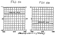
- FIG. 4 shows the characteristics of a 100 MHz wide Bessel filter. The passband delay variation of such a filter would not exceed 20 picoseconds. Combined with filters of similar design in antenna preamplifiers circuits, they would introduce less than a 30-picosecond delay variation across the 10-MHz P-code bandwidth in GLONASS.
- FIG. 3 depicts a portion of a GLONASS receiver in which channel selection is effected digitally instead of using an individual filter for each channel.
- Input signals from an antenna are amplified and filtered in amplifiers 18 and 19 and bandpass filters 20 and 21.
- the amplified and filtered signals are input to a digital sampler in the form of a two-bit analog-to-digital converters 22.
- digital selection of GLONASS channels is the preferred approach, the bandpass filter 20 still introduces large unknown delays that vary from one channel to another.
- the A/D converter 22 is driven from a reference clock source 23, which generates a clock signal at a frequency F REF , a harmonic of which is used as the sampling frequency.
- the next step shown in processing the digital signals is to generate in-phase (I) and quadrature (Q) components, using conventional digital processing.
- the digital samples from the analog-to-digital converter 22 are input to two multipliers 24.1 and 24.2, where each sample is multiplied by cosine and sine values, respectively, for the phase angle corresponding to the digital sample, the cosine and sine values being obtained from a sin/cos lookup memory 25.
- Successive values of the sine and cosine products from the multipliers 24.1 and 24.2 are accumulated in an I summation circuit 26.1 and a Q summation circuit 26.2.
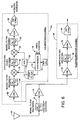
- the output of low-noise amplifier 32 is also coupled to a calibration channel 50, which computes phase or delay corrections for each of the channels, based on bandpass filtering each channel in turn at a common intermediate frequency.
- the calibration channel 50 includes a first low-noise amplifier 52, a first 200 MHz wide Bessel filter 54, a first frequency mixer 56, a narrow 10 MHz wide filter 58, a second frequency mixer 60, a second 200 MHz wide Bessel filter 62, a second low-noise amplifier 64 and an analog-to-digital converter 66.
- the first mixer 56 downconverts the incoming signal to selected intermediate frequency, at which the downconverted signal is bandpass filtered in the narrow filter 58, to select a particular channel.
- the resulting filtered signal is then upconverted by the second mixer 60, to its original L-band frequency, after which the signal is amplified in amplifier 64 and converted to digital form in the converter 66.
- Other important components of the calibration channel 50 include a voltage controlled oscillator (VCO) 68, which generates signals of an appropriate frequency to supply to the first and second mixers 56 and 60, such that the incoming signal is downshifted by an amount selected to place a selected receiver channel frequency at the center of the passband of the 10 MHz filter 58. Since each receiver channel uses different frequency bands, each must be down-shifted by a different amount to place it in overlapping relationship with the filter 58.
- VCO voltage controlled oscillator
- the present invention provides for bandpass filtering of each channel using a single bandpass filter centered at a common intermediate frequency. Therefore, for each channel in turn, the calibration channel 50 provides phase measurements that are not subject to these channel-to-channel differences. Utilization of these calibration measurements requires just a few additional components, including a demultiplexer 94, phase correction storage means 96 for each GLONASS channel, and a signal subractor circuit 98 for each channel.
- Satellite channel selection signals are applied to line 76, which effects frequency control of the calibration channel 50, as discussed with reference to FIG. 6, and simultaneously controls the demultiplexer 94.
- Phase measurements from the calibration channel phase tracking and measurement circuit 92 are directed by the demulitplexer 94 to an appropriate phase correction storage element 96.
- the phase measurement from the circuit 92 is directed to phase correction storage unit 96.1.
- the satellite selection signals select each channel in turn on a periodic basis, such as every few seconds or every few minutes.
- the phase correction storage units 96 contain the most recent phase calibration corrections for each of the receiver channels.
- Phase measurements generated by the phase tracking and measurement circuits 90 are automatically adjusted in the signal subtractors 98, to produce corrected phase signals for each of the receiver channels.
- the sampling filters 40 in the GLONASS channels 36 and the roving filter 58 in the calibration channel 50 are preferably constructed of ceramic material, which has a low temperature coefficient.
- the variation of filter delay characteristics as a function of temperature can be expected to be relatively small.
- ambient temperature variation is relatively slow because the circuitry is housed in an insulated enclosure that interposes long thermal time constants. Therefore, calibration can proceed at a relatively slow pace without loss of accuracy in any of the channels.
- the present invention represents a significant advance in the field of GLONASS receiver design for precision location measurements.
- the invention permits the use of GLONASS satellites for highly accurate survey and other applications.
- Receivers using a combination of GLONASS and GPS satellites provide for faster determination of location measurements, or, in some environmental conditions, may mean the difference between obtaining a solution or not doing so, simply because of the larger number of satellites that GLONASS provides when used in combination with GPS.
Landscapes
- Engineering & Computer Science (AREA)
- Radar, Positioning & Navigation (AREA)
- Remote Sensing (AREA)
- Computer Networks & Wireless Communication (AREA)
- Physics & Mathematics (AREA)
- General Physics & Mathematics (AREA)
- Signal Processing (AREA)
- Position Fixing By Use Of Radio Waves (AREA)
- Radio Relay Systems (AREA)
- Telephonic Communication Services (AREA)
- Spark Plugs (AREA)
- Management, Administration, Business Operations System, And Electronic Commerce (AREA)
- Monitoring And Testing Of Transmission In General (AREA)
- Testing, Inspecting, Measuring Of Stereoscopic Televisions And Televisions (AREA)
Claims (10)
- Un récepteur pour système de satellite à orbite globale (GLONASS), comprenant :un sous-système d'antenne pour recevoir des signaux venant d'une pluralité de satellites en orbite,un canal de récepteur classique, couplé au sous-système d'antenne, le canal de récepteur étant conçu pour une fonction de réception, de filtrage passe-bande et de sélection numérique, sur les fréquences des signaux venant d'une pluralité de satellites en orbite, dans lequel les satellites sont distingués par utilisation de fréquences de porteuses différentes ; caractérisé par le fait de comprendre en outre :un canal d'étalonnage, comprenant un filtre passe-bande à caractéristique étroite unique, centré à une fréquence intermédiaire sélectionnée, et des moyens pour traiter des signaux venant de chacun des satellites, tour à tour, par le filtre unique, pour fournir pour chaque canal une mesure de phase de porteuse de référence qui soit indépendante des effets survenant de la variation de délai de groupe introduit par le filtre passe-bande dans le récepteur.
- Un récepteur pour système de satellite à orbite globale (GLONASS), tel que défini à la revendication 1, dans lequel les moyens de traitement de signaux venant de chacun des satellites tour à tour par le filtre comprennent :un premier mélangeur de fréquence, pour effectuer une conversion descendante de signaux reçus du sous-système d'antenne à la fréquence intermédiaire sélectionnée,un deuxième mélangeur de fréquence, pour effectuer une conversion ascendante des signaux produits par le filtre passe-bande à caractéristique étroite, par la même fréquence que celle à laquelle les signaux étaient l'objet d'une conversion descendante dans le premier mélangeur de fréquence,un générateur de signal local, fournissant aux premier et deuxième mélangeurs de fréquence un signal à une fréquence qui est la différence, entre la fréquence de porteuse des signaux reçus depuis un satellite sélectionné et la fréquence intermédiaire ; etdes moyens pour appliquer des signaux de sélection de satellite destinés au générateur de signal local, pour effectuer la sélection de signaux de satellites différents, tout à tour, afin d'effectuer un traitement par le filtre passe-bande à caractéristique étroite.
- Un récepteur pour système de satellite à orbite globale (GLONASS), tel que défini à la revendication 2, et comprenant en outre :des moyens pour stocker les mesures de phase de porteuse de référence correspondant à chacun de la pluralité des canaux de récepteur ; etdes moyens pour calculer la différence entre une mesure de phase de porteuse depuis chaque canal de récepteur classique et la mesure de phase de porteuse de référence correspondant au même canal, pour obtenir une mesure de phase de porteuse étalonnée pour chaque canal.
- Un récepteur pour système de satellite à orbite globale (GLONASS), tel que défini à la revendication 3, dans lequel les moyens de stocker les mesures de phase de porteuse de référence comprennent :une pluralité de cellules de stockage de mesure de phase ; etun démultiplexeur, comprenant une entrée dérivée du canal d'étalonnage, une pluralité de sorties couplées aux cellules de stockage de mesure de phase, et une entrée de signal de commande, recevant les mêmes signaux de sélection de satellites que ceux utilisés pour commander le générateur de signal local.
- Un récepteur pour système de satellite à orbite globale (GLONASS), tel que défini à la revendication 4, dans lequel :le canal d'étalonnage et le canal de récepteur classique comprennent chacun un convertisseur analogique-numérique ; etles mesures de phase de porteuse et les mesures de phase de porteuse de référence sont converties sous forme numérique, dans un but de démultiplexage et de stockage.
- Un récepteur pour système de satellite à orbite globale (GLONASS), tel que défini à la revendication 2, dans lequel le canal d'étalonnage comprend en outre :des premier et deuxième filtres passe-bande à caractéristique large, afin de supprimer les images de fréquence indésirées, qui sont des coproduits nécessaires du mélange de fréquence.
- Un procédé d'étalonnage d'un récepteur pour système de satellite à orbite globale (GLONASS), comprenant les étapes consistant à :recevoir des signaux venant d'une pluralité de satellites en orbite, chacun étant distingué par l'utilisation d'une bande de fréquence porteuse différente,effectuer un filtrage passe-bande sur la pluralité des signaux de satellite en orbite, par utilisation d'un filtre passe-bande commun usuel, dans un canal de récepteur classique,numériser le spectre de signal filtré,obtenir, à partir des signaux de canal de satellite ayant été filtrés numériquement, un jeu de mesures de phase de porteuse sujet à erreurs, résultant de l'utilisation de filtres passe-bande différents dans les canaux de récepteur,traiter les signaux reçus, tour à tour, dans un canal d'étalonnage, qui comprend un filtre passe-bande à caractéristique étroite unique, centré sur une fréquence intermédiaire sélectionnée : etgénérer, dans le canal d'étalonnage, un jeu de mesures de référence de phase de porteuse pouvant être utilisé pour corriger les mesures de phase de porteuse émanant des canaux de récepteur classiques.
- Un procédé selon la revendication 7, dans lequel l'étape de traitement des signaux reçus dans le canal d'étalonnage comprend :la conversion descendante des signaux reçus par une fréquence de différence, sélectionnée pour positionner la bande de fréquence des signaux venant d'un satellite sélectionné, sur la bande intermédiaire,le filtrage passe-bande les signaux ayant subi une conversion descendante,la conversion montante des signaux après le filtrage passe-bande, par la même fréquence de différence sélectionnée que celle utilisée à l'étape de conversion descendante ; etla sélection périodique d'un satellite différent, par changement de la fréquence de différence sélectionnée utilisée aux étapes de conversion descendante et de conversion ascendante,et dans lequel l'étape de génération d'un jeu de mesures de référence de phase de porteuse comprend la recherche et la mesure de la phase de porteuse pour chacun des satellites sélectionnés, le stockage des mesures de phase de porteuse résultant des étapes de traitement précédentes.
- Un procédé selon la revendication 8, dans lequel l'étape de génération d'un jeu de signaux de référence de phase de porteuse comprend, en outre :la réception de mesures de phase de porteuse de référence venant du récepteur d'étalonnage ; etla distribution des mesures de phase de porteuse de référence, afin de stocker séparément des unités correspondant aux satellites séparés.
- Un procédé selon la revendication 9, et comprenant, en outre :le calcul de mesures de phases de porteuse corrigées, par calcul de la différence entre les mesures de phase de porteuse obtenues d'après les canaux récepteurs classiques et les mesures de phase de porteuse de référence correspondantes stockées dans les unités de stockage.
Applications Claiming Priority (2)
| Application Number | Priority Date | Filing Date | Title |
|---|---|---|---|
| US09/255,972 US6363123B1 (en) | 1999-02-23 | 1999-02-23 | Receiver calibration technique for global orbiting navigation satellite system (GLONASS) |
| US255972 | 2002-09-26 |
Publications (3)
| Publication Number | Publication Date |
|---|---|
| EP1031845A2 EP1031845A2 (fr) | 2000-08-30 |
| EP1031845A3 EP1031845A3 (fr) | 2003-05-14 |
| EP1031845B1 true EP1031845B1 (fr) | 2004-09-15 |
Family
ID=22970625
Family Applications (1)
| Application Number | Title | Priority Date | Filing Date |
|---|---|---|---|
| EP00102857A Expired - Lifetime EP1031845B1 (fr) | 1999-02-23 | 2000-02-11 | Procédé de calibrage pour un récepteur de type GLONASS |
Country Status (6)
| Country | Link |
|---|---|
| US (1) | US6363123B1 (fr) |
| EP (1) | EP1031845B1 (fr) |
| AT (1) | ATE276525T1 (fr) |
| AU (1) | AU1679100A (fr) |
| CA (1) | CA2298213C (fr) |
| DE (1) | DE60013662T2 (fr) |
Cited By (1)
| Publication number | Priority date | Publication date | Assignee | Title |
|---|---|---|---|---|
| CN111510197A (zh) * | 2020-04-01 | 2020-08-07 | 上海航天测控通信研究所 | 星载双通道多频段可选上变频装置 |
Families Citing this family (40)
| Publication number | Priority date | Publication date | Assignee | Title |
|---|---|---|---|---|
| US6816710B2 (en) * | 1998-05-06 | 2004-11-09 | Snaptrack, Inc. | Method and apparatus for signal processing in a satellite positioning system |
| US6301545B1 (en) * | 1999-04-30 | 2001-10-09 | Sirf Technology, Inc. | Global positioning system tag system |
| WO2001020359A1 (fr) * | 1999-09-13 | 2001-03-22 | Novatel Inc. | Procede de reduction des effets d'ecarts de frequences dans un recepteur |
| US6718167B2 (en) * | 2002-08-01 | 2004-04-06 | Agere Systems Inc. | Filter center frequency temperature compensation by adjustment of the operating frequency of the host system |
| US6944422B2 (en) * | 2003-04-18 | 2005-09-13 | Motorola, Inc. | Method and device for detecting an interference condition |
| US7809083B1 (en) | 2006-01-23 | 2010-10-05 | Marvell International Ltd. | Differential receiver with frequency offset compensation |
| US7881690B2 (en) * | 2006-04-07 | 2011-02-01 | Belair Networks Inc. | System and method for zero intermediate frequency filtering of information communicated in wireless networks |
| US20090117859A1 (en) * | 2006-04-07 | 2009-05-07 | Belair Networks Inc. | System and method for frequency offsetting of information communicated in mimo based wireless networks |
| US8254865B2 (en) * | 2006-04-07 | 2012-08-28 | Belair Networks | System and method for frequency offsetting of information communicated in MIMO-based wireless networks |
| US7817084B2 (en) * | 2006-08-23 | 2010-10-19 | Qualcomm Incorporated | System and/or method for reducing ambiguities in received SPS signals |
| US20080100308A1 (en) * | 2006-10-25 | 2008-05-01 | Robert Crick | Apparatus for detecting imbalances in a paired line |
| US8232807B2 (en) * | 2006-10-25 | 2012-07-31 | Textron Innovations Inc. | Apparatus for detecting imbalances in a paired line |
| JP4973206B2 (ja) * | 2007-01-16 | 2012-07-11 | セイコーエプソン株式会社 | 測位装置、電子機器、フィルタ通過帯域可変方法、プログラム及び記憶媒体 |
| JP5084543B2 (ja) * | 2008-02-12 | 2012-11-28 | キヤノン株式会社 | 画像処理装置及び画像処理方法 |
| JP2011521258A (ja) * | 2008-05-20 | 2011-07-21 | レイセオン カンパニー | 併合衛星システム信号を使用するナビゲーションのための衛星受信機および方法 |
| US8400354B2 (en) * | 2008-08-15 | 2013-03-19 | Broadcom Corporation | Method and system for calibrating group delay errors in a combined GPS and GLONASS receiver |
| WO2010033046A1 (fr) * | 2008-09-16 | 2010-03-25 | Magellan Navigation, Inc. | Systèmes et procédés pour fournir, à la volée, un étalonnage du biais de la phase de porteuse dans un système mondial de navigation par satellites (glonass) |
| US8412093B2 (en) * | 2008-10-22 | 2013-04-02 | Mediatek Inc. | Receiver applying channel selection filter for receiving satellite signal and receiving method thereof |
| US9103912B2 (en) | 2008-12-31 | 2015-08-11 | Javad Gnss, Inc. | Inter-channel bias calibration for navigation satellite systems |
| US8022868B2 (en) * | 2008-12-31 | 2011-09-20 | Javad Gnss, Inc. | Inter-channel bias calibration for navigation satellite systems |
| GB2467179B (en) * | 2009-01-27 | 2012-09-05 | Samsung Electronics Co Ltd | Data extraction from multi-carrier signals |
| US8169379B2 (en) * | 2009-02-13 | 2012-05-01 | Javad Gnss, Inc. | Portable multiband antenna |
| CN101854323B (zh) * | 2009-04-03 | 2012-12-19 | 中兴通讯股份有限公司 | 天线校准方法和系统 |
| US8803736B2 (en) * | 2010-02-26 | 2014-08-12 | Navcom Technology, Inc. | Method and system for estimating position with bias compensation |
| JP2011185603A (ja) * | 2010-03-04 | 2011-09-22 | Denso Corp | 測位装置 |
| JP2011215128A (ja) * | 2010-03-16 | 2011-10-27 | Denso Corp | Glonass受信機 |
| US9184771B2 (en) * | 2011-10-12 | 2015-11-10 | Optis Cellular Technology, Llc | Digital down conversion and demodulation |
| US10107917B2 (en) | 2011-12-05 | 2018-10-23 | Mediatek Inc. | Method of inter-channel bias calibration in a GNSS receiver and related device |
| GB2504757B (en) * | 2012-08-09 | 2015-03-25 | Nvidia Corp | Reference clock calibration |
| RU2510934C1 (ru) * | 2012-10-22 | 2014-04-10 | Открытое акционерное общество "Российская корпорация ракетно-космического приборостроения и информационных систем" (ОАО "Российские космические системы") | Автономный пункт приема гелиогеофизической информации |
| US20160349379A1 (en) * | 2015-05-28 | 2016-12-01 | Alberto Daniel Lacaze | Inertial navigation unit enhaced with atomic clock |
| CN105699997B (zh) * | 2016-03-17 | 2018-05-29 | 武汉际上导航科技有限公司 | 一种使用glonass单频信号进行差分定位的方法 |
| CN111049603A (zh) * | 2018-10-12 | 2020-04-21 | 华讯方舟科技有限公司 | 卫星信号强度检测方法和装置 |
| CN110417487B (zh) * | 2019-07-30 | 2023-06-27 | 京信网络系统股份有限公司 | 一种通道校准装置及方法、计算机装置及可读存储介质 |
| WO2021167905A1 (fr) * | 2020-02-17 | 2021-08-26 | Sam Belkin | Filtre radiofréquence accordable dynamiquement et applications |
| DE102020113742B3 (de) * | 2020-05-20 | 2021-11-04 | Forschungszentrum Jülich GmbH | Verfahren und System zum Abgleichen der Sender-Clockfrequenz und der Empfänger-Clockfrequenz, Verfahren und System zum Abgleichen einer Mischfrequenz und einer Trägerfrequenz, Verfahren und System zur Positionsbestimmung |
| CN113411140B (zh) * | 2021-05-27 | 2022-06-03 | 中国人民解放军国防科技大学 | 信道自适应通道特性学习方法及其模拟器、卫星导航系统 |
| US12123955B2 (en) | 2021-06-11 | 2024-10-22 | Robotic Research Opco, Llc | Systems and methods for selective global navigation satellite system (GNSS) navigation |
| CN113985451B (zh) * | 2021-10-25 | 2022-11-15 | 湘潭大学 | 一种基于卡尔曼滤波跟踪环路的导航欺骗检测方法和装置 |
| KR20240023014A (ko) * | 2022-08-11 | 2024-02-20 | 엘지전자 주식회사 | 무선 통신 시스템에서 무선 신호 송수신 방법 및 장치 |
Family Cites Families (13)
| Publication number | Priority date | Publication date | Assignee | Title |
|---|---|---|---|---|
| US5134407A (en) * | 1991-04-10 | 1992-07-28 | Ashtech Telesis, Inc. | Global positioning system receiver digital processing technique |
| US5311194A (en) * | 1992-09-15 | 1994-05-10 | Navsys Corporation | GPS precision approach and landing system for aircraft |
| US5630208A (en) * | 1994-07-19 | 1997-05-13 | Trimble Navigation Limited | Adaptive multipath equalization |
| US5526291A (en) * | 1994-09-08 | 1996-06-11 | Trimble Navigation Limited | Compensation for receiver and satellite signal differences |
| US5831574A (en) * | 1996-03-08 | 1998-11-03 | Snaptrack, Inc. | Method and apparatus for determining the location of an object which may have an obstructed view of the sky |
| DE69638262D1 (de) * | 1995-10-09 | 2010-10-28 | Snaptrack Inc | GPS-Empfänger und Verfahren zur Verarbeitung von GPS-Signalen |
| US5874914A (en) * | 1995-10-09 | 1999-02-23 | Snaptrack, Inc. | GPS receiver utilizing a communication link |
| US5884214A (en) * | 1996-09-06 | 1999-03-16 | Snaptrack, Inc. | GPS receiver and method for processing GPS signals |
| US5724046A (en) * | 1996-02-01 | 1998-03-03 | Trimble Navigation Limited | Method and system for using a single code generator to provide multi-phased independently controllable outputs in a navigation satellite receiver |
| JP3231624B2 (ja) * | 1996-05-17 | 2001-11-26 | 松下電器産業株式会社 | Gps受信機 |
| CA2283904C (fr) * | 1997-03-21 | 2007-01-09 | The Board Of Trustees Of The Leland Stanford Junior University | Systeme de navigation a precision centimetrique utilisant des satellites en orbite basse |
| US5914685A (en) * | 1997-04-25 | 1999-06-22 | Magellan Corporation | Relative position measuring techniques using both GPS and GLONASS carrier phase measurements |
| US6091785A (en) * | 1997-09-25 | 2000-07-18 | Trimble Navigation Limited | Receiver having a memory based search for fast acquisition of a spread spectrum signal |
-
1999
- 1999-02-23 US US09/255,972 patent/US6363123B1/en not_active Expired - Lifetime
-
2000
- 2000-02-07 CA CA002298213A patent/CA2298213C/fr not_active Expired - Fee Related
- 2000-02-11 AT AT00102857T patent/ATE276525T1/de not_active IP Right Cessation
- 2000-02-11 DE DE60013662T patent/DE60013662T2/de not_active Expired - Lifetime
- 2000-02-11 EP EP00102857A patent/EP1031845B1/fr not_active Expired - Lifetime
- 2000-02-15 AU AU16791/00A patent/AU1679100A/en not_active Abandoned
Cited By (1)
| Publication number | Priority date | Publication date | Assignee | Title |
|---|---|---|---|---|
| CN111510197A (zh) * | 2020-04-01 | 2020-08-07 | 上海航天测控通信研究所 | 星载双通道多频段可选上变频装置 |
Also Published As
| Publication number | Publication date |
|---|---|
| EP1031845A3 (fr) | 2003-05-14 |
| US6363123B1 (en) | 2002-03-26 |
| AU1679100A (en) | 2000-08-24 |
| DE60013662D1 (de) | 2004-10-21 |
| CA2298213A1 (fr) | 2000-08-23 |
| CA2298213C (fr) | 2008-04-22 |
| DE60013662T2 (de) | 2005-11-10 |
| EP1031845A2 (fr) | 2000-08-30 |
| ATE276525T1 (de) | 2004-10-15 |
Similar Documents
| Publication | Publication Date | Title |
|---|---|---|
| EP1031845B1 (fr) | Procédé de calibrage pour un récepteur de type GLONASS | |
| US5414729A (en) | Pseudorandom noise ranging receiver which compensates for multipath distortion by making use of multiple correlator time delay spacing | |
| US4894842A (en) | Precorrelation digital spread spectrum receiver | |
| US5949372A (en) | Signal injection for calibration of pseudo-range errors in satellite positioning system receivers | |
| US6061390A (en) | P-code enhanced method for processing encrypted GPS signals without knowledge of the encryption code | |
| US7764226B1 (en) | Universal digital channel for receiving signals of global navigation satellite systems | |
| US5805108A (en) | Apparatus and method for processing multiple frequencies in satellite navigation systems | |
| JP3138952B2 (ja) | 航空機用のgps精測進入着陸システム | |
| US5808582A (en) | Global positioning system receiver with improved multipath signal rejection | |
| US5526291A (en) | Compensation for receiver and satellite signal differences | |
| EP0198029B1 (fr) | Traitement dans la gamme delta d'un systeme de positionnement global ameliore | |
| EP0351156B1 (fr) | Récepteur d'un système de détermination de position du type GPS comportant des sections à fréquence radio et à traitement numérique | |
| US6069583A (en) | Receiver for a navigation system, in particular a satellite navigation system | |
| US8456353B2 (en) | Method and system for determining clock corrections | |
| CA2012916C (fr) | Calcul de la vitesse d'un recepteur spg par methode doppler differentielle | |
| US5907578A (en) | Weighted carrier phase multipath reduction | |
| RU2417382C2 (ru) | Архитектура обработки сигналов в приемнике спутниковой навигационной системы | |
| US6959057B1 (en) | Method of enhancing signal tracking in global positioning system receivers | |
| EP0552975B1 (fr) | Récepteur pour signaux de bruit pseudo-aléatoires, compensant les distortions de lignes multiples par réglage dynamique du retardement entre le premier et le dernier corrélateur | |
| JPH04269682A (ja) | 全地球位置発見システム用多重チャネルディジタル受信機 | |
| US6608998B1 (en) | Method for reducing inter-frequency bias effects in a receiver | |
| US7180445B2 (en) | Satellite positioning receiver using two signal carriers | |
| US7221313B2 (en) | GPS receiver with calibrator | |
| JP4916660B2 (ja) | 衛星測位システムにおける支援 | |
| JPH0242374A (ja) | 地球軌道衛星からの擬レンジを求める方法 |
Legal Events
| Date | Code | Title | Description |
|---|---|---|---|
| PUAI | Public reference made under article 153(3) epc to a published international application that has entered the european phase |
Free format text: ORIGINAL CODE: 0009012 |
|
| AK | Designated contracting states |
Kind code of ref document: A2 Designated state(s): AT BE CH CY DE DK ES FI FR GB GR IE IT LI LU MC NL PT SE |
|
| AX | Request for extension of the european patent |
Free format text: AL;LT;LV;MK;RO;SI |
|
| PUAL | Search report despatched |
Free format text: ORIGINAL CODE: 0009013 |
|
| AK | Designated contracting states |
Designated state(s): AT BE CH CY DE DK ES FI FR GB GR IE IT LI LU MC NL PT SE |
|
| AX | Request for extension of the european patent |
Extension state: AL LT LV MK RO SI |
|
| 17P | Request for examination filed |
Effective date: 20031025 |
|
| AKX | Designation fees paid |
Designated state(s): AT BE CH CY DE DK ES FI FR GB GR IE IT LI LU MC NL PT SE |
|
| GRAP | Despatch of communication of intention to grant a patent |
Free format text: ORIGINAL CODE: EPIDOSNIGR1 |
|
| GRAS | Grant fee paid |
Free format text: ORIGINAL CODE: EPIDOSNIGR3 |
|
| GRAA | (expected) grant |
Free format text: ORIGINAL CODE: 0009210 |
|
| AK | Designated contracting states |
Kind code of ref document: B1 Designated state(s): AT BE CH CY DE DK ES FI FR GB GR IE IT LI LU MC NL PT SE |
|
| PG25 | Lapsed in a contracting state [announced via postgrant information from national office to epo] |
Ref country code: IT Free format text: LAPSE BECAUSE OF FAILURE TO SUBMIT A TRANSLATION OF THE DESCRIPTION OR TO PAY THE FEE WITHIN THE PRESCRIBED TIME-LIMIT;WARNING: LAPSES OF ITALIAN PATENTS WITH EFFECTIVE DATE BEFORE 2007 MAY HAVE OCCURRED AT ANY TIME BEFORE 2007. THE CORRECT EFFECTIVE DATE MAY BE DIFFERENT FROM THE ONE RECORDED. Effective date: 20040915 Ref country code: AT Free format text: LAPSE BECAUSE OF FAILURE TO SUBMIT A TRANSLATION OF THE DESCRIPTION OR TO PAY THE FEE WITHIN THE PRESCRIBED TIME-LIMIT Effective date: 20040915 Ref country code: NL Free format text: LAPSE BECAUSE OF FAILURE TO SUBMIT A TRANSLATION OF THE DESCRIPTION OR TO PAY THE FEE WITHIN THE PRESCRIBED TIME-LIMIT Effective date: 20040915 Ref country code: ES Free format text: LAPSE BECAUSE OF FAILURE TO SUBMIT A TRANSLATION OF THE DESCRIPTION OR TO PAY THE FEE WITHIN THE PRESCRIBED TIME-LIMIT Effective date: 20040915 Ref country code: BE Free format text: LAPSE BECAUSE OF FAILURE TO SUBMIT A TRANSLATION OF THE DESCRIPTION OR TO PAY THE FEE WITHIN THE PRESCRIBED TIME-LIMIT Effective date: 20040915 Ref country code: FI Free format text: LAPSE BECAUSE OF FAILURE TO SUBMIT A TRANSLATION OF THE DESCRIPTION OR TO PAY THE FEE WITHIN THE PRESCRIBED TIME-LIMIT Effective date: 20040915 |
|
| REG | Reference to a national code |
Ref country code: GB Ref legal event code: FG4D Ref country code: CH Ref legal event code: EP |
|
| REG | Reference to a national code |
Ref country code: IE Ref legal event code: FG4D |
|
| REF | Corresponds to: |
Ref document number: 60013662 Country of ref document: DE Date of ref document: 20041021 Kind code of ref document: P |
|
| REG | Reference to a national code |
Ref country code: CH Ref legal event code: NV Representative=s name: BUECHEL, KAMINSKI & PARTNER PATENTANWAELTE ESTABLI |
|
| PG25 | Lapsed in a contracting state [announced via postgrant information from national office to epo] |
Ref country code: SE Free format text: LAPSE BECAUSE OF FAILURE TO SUBMIT A TRANSLATION OF THE DESCRIPTION OR TO PAY THE FEE WITHIN THE PRESCRIBED TIME-LIMIT Effective date: 20041215 Ref country code: DK Free format text: LAPSE BECAUSE OF FAILURE TO SUBMIT A TRANSLATION OF THE DESCRIPTION OR TO PAY THE FEE WITHIN THE PRESCRIBED TIME-LIMIT Effective date: 20041215 Ref country code: GR Free format text: LAPSE BECAUSE OF FAILURE TO SUBMIT A TRANSLATION OF THE DESCRIPTION OR TO PAY THE FEE WITHIN THE PRESCRIBED TIME-LIMIT Effective date: 20041215 |
|
| PG25 | Lapsed in a contracting state [announced via postgrant information from national office to epo] |
Ref country code: CY Free format text: LAPSE BECAUSE OF FAILURE TO SUBMIT A TRANSLATION OF THE DESCRIPTION OR TO PAY THE FEE WITHIN THE PRESCRIBED TIME-LIMIT Effective date: 20050211 Ref country code: LU Free format text: LAPSE BECAUSE OF NON-PAYMENT OF DUE FEES Effective date: 20050211 Ref country code: IE Free format text: LAPSE BECAUSE OF NON-PAYMENT OF DUE FEES Effective date: 20050211 |
|
| PG25 | Lapsed in a contracting state [announced via postgrant information from national office to epo] |
Ref country code: MC Free format text: LAPSE BECAUSE OF NON-PAYMENT OF DUE FEES Effective date: 20050228 |
|
| NLV1 | Nl: lapsed or annulled due to failure to fulfill the requirements of art. 29p and 29m of the patents act | ||
| PLBE | No opposition filed within time limit |
Free format text: ORIGINAL CODE: 0009261 |
|
| STAA | Information on the status of an ep patent application or granted ep patent |
Free format text: STATUS: NO OPPOSITION FILED WITHIN TIME LIMIT |
|
| ET | Fr: translation filed | ||
| 26N | No opposition filed |
Effective date: 20050616 |
|
| REG | Reference to a national code |
Ref country code: IE Ref legal event code: MM4A |
|
| PG25 | Lapsed in a contracting state [announced via postgrant information from national office to epo] |
Ref country code: PT Free format text: LAPSE BECAUSE OF NON-PAYMENT OF DUE FEES Effective date: 20050215 |
|
| REG | Reference to a national code |
Ref country code: CH Ref legal event code: PFA Owner name: LEICA GEOSYSTEMS INC. Free format text: LEICA GEOSYSTEMS INC.#3155 MEDLOCK BRIDGE ROAD#NORCROSS, GA 30071 (US) -TRANSFER TO- LEICA GEOSYSTEMS INC.#3155 MEDLOCK BRIDGE ROAD#NORCROSS, GA 30071 (US) |
|
| REG | Reference to a national code |
Ref country code: FR Ref legal event code: PLFP Year of fee payment: 17 |
|
| REG | Reference to a national code |
Ref country code: FR Ref legal event code: PLFP Year of fee payment: 18 |
|
| REG | Reference to a national code |
Ref country code: FR Ref legal event code: PLFP Year of fee payment: 19 |
|
| PGFP | Annual fee paid to national office [announced via postgrant information from national office to epo] |
Ref country code: CH Payment date: 20180216 Year of fee payment: 19 Ref country code: GB Payment date: 20180216 Year of fee payment: 19 Ref country code: DE Payment date: 20180219 Year of fee payment: 19 |
|
| PGFP | Annual fee paid to national office [announced via postgrant information from national office to epo] |
Ref country code: FR Payment date: 20180222 Year of fee payment: 19 |
|
| REG | Reference to a national code |
Ref country code: DE Ref legal event code: R119 Ref document number: 60013662 Country of ref document: DE |
|
| REG | Reference to a national code |
Ref country code: CH Ref legal event code: PL |
|
| GBPC | Gb: european patent ceased through non-payment of renewal fee |
Effective date: 20190211 |
|
| PG25 | Lapsed in a contracting state [announced via postgrant information from national office to epo] |
Ref country code: CH Free format text: LAPSE BECAUSE OF NON-PAYMENT OF DUE FEES Effective date: 20190228 Ref country code: LI Free format text: LAPSE BECAUSE OF NON-PAYMENT OF DUE FEES Effective date: 20190228 |
|
| PG25 | Lapsed in a contracting state [announced via postgrant information from national office to epo] |
Ref country code: DE Free format text: LAPSE BECAUSE OF NON-PAYMENT OF DUE FEES Effective date: 20190903 Ref country code: GB Free format text: LAPSE BECAUSE OF NON-PAYMENT OF DUE FEES Effective date: 20190211 |
|
| PG25 | Lapsed in a contracting state [announced via postgrant information from national office to epo] |
Ref country code: FR Free format text: LAPSE BECAUSE OF NON-PAYMENT OF DUE FEES Effective date: 20190228 |