EP1031948A2 - Münzausgabevorrichtung - Google Patents
Münzausgabevorrichtung Download PDFInfo
- Publication number
- EP1031948A2 EP1031948A2 EP00301472A EP00301472A EP1031948A2 EP 1031948 A2 EP1031948 A2 EP 1031948A2 EP 00301472 A EP00301472 A EP 00301472A EP 00301472 A EP00301472 A EP 00301472A EP 1031948 A2 EP1031948 A2 EP 1031948A2
- Authority
- EP
- European Patent Office
- Prior art keywords
- tank
- coin
- coins
- high capacity
- conveyor
- Prior art date
- Legal status (The legal status is an assumption and is not a legal conclusion. Google has not performed a legal analysis and makes no representation as to the accuracy of the status listed.)
- Ceased
Links
Images




Classifications
-
- G—PHYSICS
- G07—CHECKING-DEVICES
- G07D—HANDLING OF COINS OR VALUABLE PAPERS, e.g. TESTING, SORTING BY DENOMINATIONS, COUNTING, DISPENSING, CHANGING OR DEPOSITING
- G07D9/00—Counting coins; Handling of coins not provided for in the other groups of this subclass
-
- G—PHYSICS
- G07—CHECKING-DEVICES
- G07D—HANDLING OF COINS OR VALUABLE PAPERS, e.g. TESTING, SORTING BY DENOMINATIONS, COUNTING, DISPENSING, CHANGING OR DEPOSITING
- G07D9/00—Counting coins; Handling of coins not provided for in the other groups of this subclass
- G07D9/008—Feeding coins from bulk
Definitions
- the present invention relates to a coin hopper apparatus for storing in bulk coins, tokens or other disc bodies and dispensing them individually.
- the apparatus is of particular use in gaming machines.
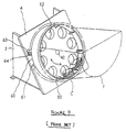
- FIG. 9 A perspective view of the coin hopper apparatus of the latter citation is shown in Figure 9 of the present application and a front elevation is illustrated in Figure 10.
- the apparatus has a base plate 4 and is stood tilted at an angle by support frames 3.
- a coin storage tank 1 for storing coins C is mounted on this base plate 4.
- the coin tank 1 has a coin exit 60 and has a coin feed disc, which may otherwise be referred to as a rotary dispensing disc, 50 freely rotatably mounted therewithin on a motorized drive shaft 42.
- the coin feed disc 50 has the form of a deep plate or pan with a thick floor and integral side wall. In the bottom of the disc 50 there are formed several coin-receiving holes 52 spaced circumferentially therearound at intervals.
- the disc 50 is rotated by the rotatable drive shaft 42 within the tank 1 in the clockwise direction illustrated by arrow A.
- the rotation of the disc 50 agitates the coins in the tank 1 and the coins are brought into the respective holes 52 of the disc 50.
- a number of guide fingers 53 are provided on the lower surface of the disc 50 projecting between the coin receiving holes 52 (see Figure 10).
- the guide fingers 53 are angled relative to the radius of disc 50 as can be clearly seen in Figure 10. They project from the floor of the disc 50 slightly higher than coin thickness.
- a support mount 54 which is concentric with the output shaft 42 projects from the base plate 4.
- the height of the support mount 54 is somewhat greater than the thickness of each coin.
- the disc 50 freely rotatably mounts to the support mount 54.
- Each coin falls in turn through a coin receiving hole 52 to between adjacent guide fingers 53 on the underside of the disc 50.
- An elliptical coin guide plate 55 is loosely fitted around the circumference of support mount 54 on the base plate 4. This guide plate 55 has a guide portion 56 to direct coins to the coin exit 60 from the tank 1. The coin exit 60 is downstream of the exit guide portion 56 of the guide plate 55.
- the guide finger 53 guides the respective coin along the elliptic guide portion 55 in the clockwise direction illustrated by arrow A to the exit 60.
- a guide roller 61 is rotatably mounted on a shaft 62 external to the coin exit 60 opposite to a mobile guide roller 63, which is freely rotatably mounted on a shaft 64. Mobility of the guide roller 63 is enabled by the mounting of the shaft 64 thereof on a swing-able actuator 66.
- the shaft 64 of guide roller 63 passes up through the base plate 4 via an arcuate groove/window 65 in the base plate 4.
- the swing-able actuator 66 is rotatably installed on a bracket 67 provided on the underside of the base plate 4. This actuator 66 is installed on a shaft 68 on the bracket 67 and retained by a spring.
- a count sensor (not shown) operated by actuator 66 is installed on the bracket 67 and the actuator 66 is pushed and moved by mobile guide roller 63 forcing out the coin C which passes out through the coin exit 60. Finally, the coin is guided out and away from the exist 60 between the static guide roller 61 and mobile guide roller 63 while the mobile guide roller 63 is pushed and moved by the passing coin.
- the linked actuator 66 operates the sensor and counts the dispensed coins.
- a high capacity coin hopper which comprises: a first tank means for storage of coins and which has a substantially tubular form and which has an exit for coins; a rotary coin dispensing means to dispense coins from the first tank means and which is freely rotatably mounted within said first tank means; a drive means for driving the rotary coin dispensing means; and characterized by a second tank means for high capacity coin storage and which is in communication with the first tank means via an intermediate tubular case means, a conveyor means being provided within the intermediate tubular case means for transferring coins from the second tank means to the first tank means.
- the conveyor means is a belt conveyor and which will suitably serve to transfer coins collectively either in a continuous flow or in batches at intervals by pusher means on the conveyor means.
- the conveyor means might be a chain conveyor in alternative to being a belt conveyor.
- the rotary coin dispensing means and the conveying means are each driven by a common said drive means.
- the rotary dispensing means and the conveying means are each controllably selectively connected with the said drive means.
- the conveyor means may be an endless belt and may be, for example, of so-called caterpillar form being composed of a plurality of rectangular plates which are consecutively hinged together in a chain.
- the floor of the case means is arranged to be lower than the floor of the first tank means in use in order that a substantial reserve of coins be held back in the case and second storage tank for controlled supply to the first tank by the conveyor means.
- the apparatus of the invention comprises a substantially tubular first tank 1 mounted to a backing plate 4 and having a rotary dispensing means/coin feed disc 50 rotatably mounted within the first tank 1 in essentially the same manner as for the prior art apparatus described with respect to Figures 9 and 10 in the introduction to this application.
- Common reference numerals are used between the Figures 9 and 10 illustrating that prior art and the Figures 1 to 8 illustrating the present first preferred embodiment.
- the first tank 1 is open at its front face, being the face facing away from the rotary disc 50 and backing board 4 to communicate with a high capacity second tank 2 formed of metal or a resin moulding to have a large pot shape into which large volumes of coins may be charged via charge opening 5 and stored in a loosely piled condition.
- the second tank 2 communicates with the first tank 1 via an intermediate tubular casing 10. In the illustrated embodiment this is shown as being separate from but integrally assembled with each of the first tank 1 and second tank 2 but may alternatively be integrally formed with either or both of the first tank 1 and second tank 2.
- the second tank 2 functions as a reserve chamber and does not simply extend the capacity of the first tank 1. Replenishment of the first tank 1 is determined by the rate of transfer of coins from the second tank 2 to the first tank 1.
- the transfer of coins is powered by a conveyor belt 14 that is mounted to circulate around the internal wall of the intermediate tubular casing 10 raising the heaps of coins toward the opening into the first tank 1.
- the conveyor belt 14 is an endless belt which suitably consists of rubber, leather or cloth, for example.
- the internally directed transport surface of the belt 14 is provided with pusher protuberances 15 at spaced intervals there along and it is these that push the coins collectively to raise them to spill into the first tank 1.
- the width of the conveyor belt 14 and the spacing between the pusher protruberances 15 are suitably multiples of a coin diameter in size.
- the conveyor belt 14 is driven by a common drive mechanism with the drive for the rotary dispensing means/disc 50.
- first clutch 47 mounted on output shaft 42 for driving the rotary disc 50.
- the output shaft 42 extends from gear housing 41.
- a second clutch 48 is provided mounted on an output shaft 43 for driving the conveyor belt 14.
- the rotary coin dispensing disc 50 is rotated under the action of the first clutch 47, clockwise in the first tank 1, while the drive motor 40 is rotated positively.
- the conveyor belt 14 in the intermediate case 10 may be stopped under the action of the second clutch 48 at this time.
- coins in first tank 1 are agitated by the protrusions on the disc 50 and fall into the receiving holes 52 of the disc 50.
- Each received coin passes through a receiving hole 52 and is then supported on base plate 4 to then be propelled by the guiding finger 53 in the direction of arrow A toward the coin exit 60 along the guide surface 56 of the guide plate 55 as described previously with reference to the prior art.
- each coin as it is dispensed moves the mobile guide roller 63 causing actuator 66 to operate a coin counting sensor.
- the second tank 2 has its floor below the level of the first tank 1 a large proportion of coins may be held in reserve in the second tank 2. Accordingly, when the volume of coins in the first tank 1 has diminished as can be automatically established from the change of the load current for the drive motor 40, the motor 40 may then be reversed. Any suitable sensor for the residual quantity of coins may be used to sense depletion below any predetermined threshold value in order to activate the reversal of the motor 40.
- Rotation of the coin dispensing disc 50 within the first tank 1 is stopped by the action of the first clutch 47 and the power of the motor 40 is transmitted by the action of the second clutch 48 to the conveyor belt 14 in the intermediate case 10.
- the conveyor belt 14 is then driven to circulate in, for example, a counter clockwise direction.
- the conveyor belt 14 will then act to raise coins, pushed up by the plurality protuberances 15 on the belt 14. As the coins are raised they will slide over a sloping/curved wall 9 of the apparatus and into the first tank 1 through opening 13, thereby supplementing or replenishing the coins within the first tank 1.
- the transfer of coins from the second tank 1 to the first tank 1 may then be carried out continuously at a predetermined rate and/or for a predetermined time interval.
- the drive motor 40 is halted to stop the supplementation of coins when the dispensing of coins is ended.
- the drive motor 40 may then be rotated positively again, commensurate with renewed dispensing of coins.
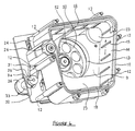
- gear case 41 is fixed to the rear surface of base plate 4 by screws and the motor 40 is fixed onto this gear case 41 by screws (see Figure 3).
- gear case 41 there are provided: pinion 44 fixed on motor shaft 40; large gear 45 engaging with pinion 44; and output gear 46 engaging with gear 45 (see Figure 4).
- First clutch 47 and second clutch 48 are mounted on output gear 46. Output shaft 42 is driven by the action of first clutch 47 when the motor 40 is rotated in the positive direction while output shaft 43 is driven by the action of clutch 48 when the motor 40 is reversed.
- the output shaft 42 drives rotation of the rotary dispensing disc 50 while the conveyor belt 14 is stopped through disengagement of the second clutch 48.
- the output shaft 43 is turned with the second clutch 48 engaged and thereby turns the conveyor belt 14 but the first clutch 47 is disengaged and, therefore, the disc 50 ceases to rotate.
- Uni-directional clutches are suitably used for the first clutch 47 and second clutch 48.
- solenoid-type magnetic clutches could also be used, for example.
- the output shaft 42 rotates the coin dispensing disc 50 in the first tank 1 during positive rotation of the motor 40.
- the coin dispensing disc 50 is secured by a bolt 51 onto the output shaft 42.
- the rotary disc 50 suitably has a pan-shaped form comprising a relatively thick bottom plate and integral upstanding circumferential wall.
- the bottom of the rotary dispensing disc 50 has a plurality of coin receiving holes 52 and has the guide fingers on the underside of the disc 50 projecting between the holes 52 to guide the coins. Again, the height of these guide fingers is less than the thickness of each coin.
- a pulley 38 is installed on the output shaft 43 and which is driven by the action of the second clutch 48 when the motor 40 is reverse rotated (see Figure 3).
- a pulley 36 which is fixed on the end of shaft 34 is driven by pulley 38 through an intervening drive belt 37.
- the shaft 34 projects through a bearing 33 and has a further pulley 35 installed on the alternate end thereof.
- the bearing 33 is fastened by screws 32 to the base plate 4 (see Figure 5).
- a yet further pulley 30 is fixed on the end of shaft 27 and is driven by the pulley 35 by intermediacy of a drive belt 31.
- the shaft 27 drives a yet further pulley 17 in the intermediate case 10 as can be seen from Figure 7.
- the shaft 27 projects through a bearing 29 that is fixed by screws 28 (see Figure 2).
- the bearing 29 is in turn fixed on a lid plate 24 that is fastened by screws 25 to the rear surface of the case 10 (see Figure 3).
- the intermediate case 10 is illustrated as a substantially rectangular barrel and may formed of metal or comprise a plastics moulding and is fitted to the first tank 1 (see Figure 6).
- Six legs 12 extend from the case 10 to the base 4 by bolts 11 that extend therethrough to the base 4. These legs 12 and bolts 11 extend also from a perimeter flange on the large pot-shaped second tank 2.
- intermediate case 10 Centrally at the bottom/rear of the intermediate case 10 there is provided a circular opening 3 that communicates with the first tank 1.
- the bottom right hand portion of intermediate case 10 becomes a curved wall 9 through which the opening 13 is formed.
- convex mouldings 23 are formed to cover the respective pulleys.
- Drive pulley 17 is housed within the convex moulding 23 of the left upper part of case 10 as viewed in figure 7 and pulleys 16 are respectively housed in the other three corner convex mouldings 23.
- the pulleys 16 are hinged and covered by lid plates 24 as can be seen in Figure 7.
- the lid plates 24 are fixed by screws 25 to the back surface of case 10.
- the conveyor belt 14 is mounted around the pulleys 16 and 17 that sit in the respective four corners of the intermediate case 10.
- Drive pulley 17 and the three further pulleys 16 which are provided within the intermediate case 10 press the edge of belt 14 near first tank 1. Additionally, the edge of belt 14 near the second tank 2 is held by belt presses 18. Accordingly, the belt 14 is mounted on the internal wall of the intermediate case 10 to be freely slidable.
- a tension roller 26 is provided on the left side of the intermediate case 10 for adjusting the tension of the conveyor belt 14.
- This tension roller 26 has a dumb bell shape. The slender waist of the dumb bell is forced inwardly of the case 10 by a spring and screw mechanism not shown.
- the tension rollers 26 are freely rotatably mounted on each end of a T-shaped movable shaft, respectively and ensure that the belt 14 is pressed inwardly of the intermediate case 10 so that the tension of the conveyor belt 14 is maintained substantially constant.
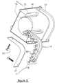
- the structure of the belt presser 18 is shown in the disassembled view of Figure 8. This comprises a roller frame 19 for holding a margin of the belt 14. Rollers 20 support the conveyor belt 14 to slide thereover and are covered beneath the slender lid plate 21.
- the belt presser 18 is installed on the intermediate case 10 by screws 22.
- a plurality of rollers 20 are used in the illustrated embodiment in order to guide the belt 14.
- bearings other than rollers may be used and the installation of the conveyor belt may be arranged in any suitable manner.
- the preferred embodiment comprises an endless belt 14, this might alternatively comprise a caterpillar type belt moulded of resin or metal.
- a single drive motor 40 is used together with a pair of clutches, first clutch 47 and second clutch 48, in an alternative and less preferred embodiment a pair of motors may be used - there being a separate dedicated motor to drive the conveyor 14.
- the rotary dispensing disc 50 is provided with coin receiving through holes 52 in an alternative embodiment the rotary disc may be without holes but having appropriate dividers and guide fingers/pins, for example.
- Such a type of rotary disc dispenser is illustrated in US 4,589,433.
- the apparatus composition and configuration as claimed provides an efficient and effective way of controlling the storage and dispensing of coins from a coin hopper.
- the communicating first 1 and second 2 tanks help to minimize the height of the apparatus while enabling a large volume of coins to be stored.
- the provision of the conveyor means to control supply from the second tank to the first tank helps to ensure that coins remaining at the bottom of the second tank can also be transported by the conveyor to the first tank 1.
Landscapes
- Physics & Mathematics (AREA)
- General Physics & Mathematics (AREA)
- Control Of Vending Devices And Auxiliary Devices For Vending Devices (AREA)
- Filling Or Emptying Of Bunkers, Hoppers, And Tanks (AREA)
- Pinball Game Machines (AREA)
Applications Claiming Priority (4)
| Application Number | Priority Date | Filing Date | Title |
|---|---|---|---|
| JP09326099A JP4332823B2 (ja) | 1999-02-24 | 1999-02-24 | 大容量コインホッパ |
| JP9326099 | 1999-02-24 | ||
| JP25165299 | 1999-09-06 | ||
| JP25165299A JP4224838B2 (ja) | 1999-09-06 | 1999-09-06 | コインホッパ |
Publications (2)
| Publication Number | Publication Date |
|---|---|
| EP1031948A2 true EP1031948A2 (de) | 2000-08-30 |
| EP1031948A3 EP1031948A3 (de) | 2002-07-24 |
Family
ID=26434673
Family Applications (1)
| Application Number | Title | Priority Date | Filing Date |
|---|---|---|---|
| EP00301472A Ceased EP1031948A3 (de) | 1999-02-24 | 2000-02-24 | Münzausgabevorrichtung |
Country Status (5)
| Country | Link |
|---|---|
| US (1) | US6328646B1 (de) |
| EP (1) | EP1031948A3 (de) |
| KR (1) | KR20000058158A (de) |
| CN (1) | CN1299246C (de) |
| AU (1) | AU761666B2 (de) |
Cited By (5)
| Publication number | Priority date | Publication date | Assignee | Title |
|---|---|---|---|---|
| EP1739633A1 (de) * | 2005-07-01 | 2007-01-03 | Asahi Seiko Co., Ltd. | Münzvereinzelungsgerät |
| CN105780160A (zh) * | 2016-04-20 | 2016-07-20 | 海宁宏高化纤有限公司 | 一种短纤维拉伸生产线上的牵伸水浴槽 |
| DE102015101421B3 (de) * | 2015-01-30 | 2016-07-28 | Crane Payment Solutions Gmbh | Vorrichtung zum Ausgeben von Münzen |
| WO2021121891A1 (en) * | 2019-12-17 | 2021-06-24 | Innovative Technology Limited | A coin elevator mechanism |
| KR102725680B1 (ko) * | 2024-06-19 | 2024-11-04 | (주)클로닉스 | 칩 디스펜서 및 그 작동 방법 |
Families Citing this family (14)
| Publication number | Priority date | Publication date | Assignee | Title |
|---|---|---|---|---|
| US6193599B1 (en) * | 1998-10-20 | 2001-02-27 | Asahi Seiko Co., Ltd. | Coin hopper device |
| TW472218B (en) * | 2000-01-28 | 2002-01-11 | Asahi Seiko Co Ltd | Coin hopper |
| TWD100843S1 (zh) | 2003-06-30 | 2004-10-11 | 旭精工股份有限公司 | 漏斗式接收器 |
| JP4810691B2 (ja) * | 2003-12-12 | 2011-11-09 | 旭精工株式会社 | コインホッパー |
| GB2416061A (en) * | 2004-07-07 | 2006-01-11 | Money Controls Ltd | Coin accepting and dispensing apparatus |
| EP2535877A1 (de) * | 2006-06-09 | 2012-12-19 | MEI, Inc. | Chargenaufladung einer münzrecyclingmaschine |
| CN101512606B (zh) * | 2006-09-11 | 2011-01-26 | 光荣株式会社 | 硬币收纳投出装置 |
| GB2510409A (en) * | 2013-02-04 | 2014-08-06 | Crane Payment Solutions Ltd | Conveying money items such as coins or tokens |
| EP2951794B1 (de) * | 2013-02-04 | 2024-01-17 | Crane Payment Innovations Limited | Förderung von geldgegenständen |
| GB2514156A (en) * | 2013-05-15 | 2014-11-19 | Crane Payment Solutions Ltd | Money item dispensing |
| GB2528287A (en) * | 2014-07-16 | 2016-01-20 | Crane Payment Solutions Ltd | Money item handling device and conveyor |
| CN105528829B (zh) * | 2016-01-08 | 2018-01-26 | 武汉科技大学 | 一种硬币清分整理机 |
| CN107284744B (zh) * | 2017-07-06 | 2022-11-01 | 南京中钞长城金融设备有限公司 | 一种贵金属币章包装设备的进料装置 |
| CN108838065A (zh) * | 2018-06-08 | 2018-11-20 | 留丹翠 | 一种下料自动包装的硬币分拣计数设备 |
Citations (5)
| Publication number | Priority date | Publication date | Assignee | Title |
|---|---|---|---|---|
| US4589433A (en) | 1983-12-07 | 1986-05-20 | Asahi Seiko Kabushiki Kaisha | Coin dispensing apparatus |
| JPS6245588A (ja) | 1985-08-17 | 1987-02-27 | ベ−リンガ−・マンハイム・ゲゼルシヤフト・ミツト・ベシユレンクテル・ハフツング | N↑6−ジ置換プリン誘導体、その製法及び該誘導体を含有するアレルギ−性疾患の治療剤 |
| JPH02152852A (ja) | 1988-05-17 | 1990-06-12 | Arcotronics It Spa | 一連のフイルムを巻いてコイルを形成することによって部品を製造する機械 |
| US5122094A (en) | 1990-06-13 | 1992-06-16 | Asahi Seiko Kabushiki Kaisha | Coin dispensing apparatus |
| EP0501607A1 (de) * | 1991-02-14 | 1992-09-02 | Bally Gaming International, Inc. | Hochleistungszuführtrichter für Münzen für einen Spielautomaten |
Family Cites Families (19)
| Publication number | Priority date | Publication date | Assignee | Title |
|---|---|---|---|---|
| FR786596A (fr) | 1935-02-26 | 1935-09-05 | Distributeur d'objets publicitaires, combiné avec un taximètre ou appareil similaire | |
| US2395732A (en) * | 1940-10-04 | 1946-02-26 | W J Savage Company Inc | Fuel feeder |
| US3061145A (en) | 1957-04-08 | 1962-10-30 | Kelsey Hayes Co | Hopper with mechanism for feeding properly oriented annular articles |
| US3680566A (en) * | 1969-09-22 | 1972-08-01 | Micro Magnetic Ind Inc | Bulk coin dispenser |
| US3910295A (en) * | 1974-01-07 | 1975-10-07 | Rowe International Inc | Bulk-loading coin hopper having endless pin chain pickup |
| US4535794A (en) | 1981-11-20 | 1985-08-20 | Coin Controls Limited | Machine having a coin or token payout mechanism |
| DE3611607A1 (de) * | 1986-04-07 | 1987-10-08 | Karl Duerr | Transportanlage mittels rohr und kette |
| FR2666315B1 (fr) * | 1990-09-04 | 1992-12-11 | France Etat | Dispositif pour controler et regulariser l'espacement de colis, paquets ou objets analogues, notamment de colis postaux. |
| US5152391A (en) * | 1991-01-14 | 1992-10-06 | Campbell Mark D | Hopper feed elevator |
| JP2767516B2 (ja) * | 1991-06-07 | 1998-06-18 | ローレルバンクマシン株式会社 | 硬貨供給装置 |
| DE4308725C2 (de) * | 1993-03-15 | 1996-12-19 | Zimmermann & Co F | Münzprüf- und Münzsortiereinrichtung mit Vertikalförderung flachliegender Münzen |
| US5333718A (en) * | 1993-08-24 | 1994-08-02 | Pannell Lorris O | Apparatus for handling plastic eating utensils |
| US5954576A (en) * | 1995-03-31 | 1999-09-21 | Spinteknology, Inc. | Coin hopper with preventive fill detector and automatic inventorying |
| SE504813C2 (sv) * | 1995-08-21 | 1997-04-28 | Scan Coin Ab | Maskin för räkning och sortering av mynt |
| US5775537A (en) * | 1995-11-14 | 1998-07-07 | Higa Development Corporation | Merchandise dispenser |
| US6174230B1 (en) * | 1997-02-28 | 2001-01-16 | Coinstar, Inc. | Method and apparatus for conditioning coins prior to discrimination |
| JP3156845B2 (ja) * | 1996-10-01 | 2001-04-16 | 旭精工株式会社 | 大容量形の円板体放出装置 |
| JP3791725B2 (ja) * | 1997-09-26 | 2006-06-28 | 旭精工株式会社 | 円板体放出装置 |
| US6003652A (en) * | 1997-12-30 | 1999-12-21 | Fuji Electric Co., Ltd. | Cash dispenser |
-
2000
- 2000-02-02 AU AU14869/00A patent/AU761666B2/en not_active Ceased
- 2000-02-18 US US09/506,982 patent/US6328646B1/en not_active Expired - Fee Related
- 2000-02-23 CN CNB001030825A patent/CN1299246C/zh not_active Expired - Fee Related
- 2000-02-23 KR KR1020000008775A patent/KR20000058158A/ko not_active Ceased
- 2000-02-24 EP EP00301472A patent/EP1031948A3/de not_active Ceased
Patent Citations (5)
| Publication number | Priority date | Publication date | Assignee | Title |
|---|---|---|---|---|
| US4589433A (en) | 1983-12-07 | 1986-05-20 | Asahi Seiko Kabushiki Kaisha | Coin dispensing apparatus |
| JPS6245588A (ja) | 1985-08-17 | 1987-02-27 | ベ−リンガ−・マンハイム・ゲゼルシヤフト・ミツト・ベシユレンクテル・ハフツング | N↑6−ジ置換プリン誘導体、その製法及び該誘導体を含有するアレルギ−性疾患の治療剤 |
| JPH02152852A (ja) | 1988-05-17 | 1990-06-12 | Arcotronics It Spa | 一連のフイルムを巻いてコイルを形成することによって部品を製造する機械 |
| US5122094A (en) | 1990-06-13 | 1992-06-16 | Asahi Seiko Kabushiki Kaisha | Coin dispensing apparatus |
| EP0501607A1 (de) * | 1991-02-14 | 1992-09-02 | Bally Gaming International, Inc. | Hochleistungszuführtrichter für Münzen für einen Spielautomaten |
Cited By (10)
| Publication number | Priority date | Publication date | Assignee | Title |
|---|---|---|---|---|
| EP1739633A1 (de) * | 2005-07-01 | 2007-01-03 | Asahi Seiko Co., Ltd. | Münzvereinzelungsgerät |
| DE102015101421B3 (de) * | 2015-01-30 | 2016-07-28 | Crane Payment Solutions Gmbh | Vorrichtung zum Ausgeben von Münzen |
| CN105780160A (zh) * | 2016-04-20 | 2016-07-20 | 海宁宏高化纤有限公司 | 一种短纤维拉伸生产线上的牵伸水浴槽 |
| CN105780160B (zh) * | 2016-04-20 | 2018-11-13 | 海宁宏高化纤有限公司 | 一种短纤维拉伸生产线上的牵伸水浴槽 |
| WO2021121891A1 (en) * | 2019-12-17 | 2021-06-24 | Innovative Technology Limited | A coin elevator mechanism |
| GB2590425A (en) * | 2019-12-17 | 2021-06-30 | Innovative Tech Ltd | A coin elevator mechanism |
| GB2606107A (en) * | 2019-12-17 | 2022-10-26 | Innovative Tech Ltd | A coin elevator machanism |
| US12469351B2 (en) | 2019-12-17 | 2025-11-11 | Innovative Technology Limited | Coin elevator mechanism |
| KR102725680B1 (ko) * | 2024-06-19 | 2024-11-04 | (주)클로닉스 | 칩 디스펜서 및 그 작동 방법 |
| WO2025263980A1 (ko) * | 2024-06-19 | 2025-12-26 | (주)클로닉스 | 칩 디스펜서 |
Also Published As
| Publication number | Publication date |
|---|---|
| CN1299246C (zh) | 2007-02-07 |
| AU761666B2 (en) | 2003-06-05 |
| AU1486900A (en) | 2000-08-31 |
| KR20000058158A (ko) | 2000-09-25 |
| US6328646B1 (en) | 2001-12-11 |
| EP1031948A3 (de) | 2002-07-24 |
| CN1264884A (zh) | 2000-08-30 |
Similar Documents
| Publication | Publication Date | Title |
|---|---|---|
| EP1031948A2 (de) | Münzausgabevorrichtung | |
| US5326312A (en) | Coin/token dispensing unit | |
| US4782790A (en) | Automatic dog feeder | |
| JPH022763B2 (de) | ||
| EP3868452B1 (de) | Spielkartenmaschine und ausgabemechanismus dafür und kartenmischverfahren | |
| JP5908753B2 (ja) | 遊技球研磨装置、同装置用球搬送ユニットおよび同装置用研磨材カセット | |
| CN109350955A (zh) | 扑克牌桌、扑克机及其扑克牌整理方法 | |
| US5254032A (en) | Coin feeding device | |
| KR100476857B1 (ko) | 대용량형디스크몸체방출장치 | |
| US3930595A (en) | Article feeding device | |
| JP5947991B2 (ja) | 遊技球研磨装置 | |
| JPH08624B2 (ja) | 遊技システムにおけるメダル配送装置 | |
| CN220090448U (zh) | 一种智能自动发牌机 | |
| JP4224838B2 (ja) | コインホッパ | |
| CN219896990U (zh) | 一种发牌机 | |
| US4725052A (en) | Paper discharging device having conveyor sections moving at different speeds | |
| JPH0540869A (ja) | 遊技システムにおけるメダル配送装置 | |
| JPS61267188A (ja) | コイン払い出し装置 | |
| JPH0512539A (ja) | 遊技システムにおけるメダル配送装置 | |
| JP2504840Y2 (ja) | 硬貨処理機の硬貨搬送装置 | |
| US4875599A (en) | Card case with powered dispenser | |
| JPH09299599A (ja) | 遊技機島 | |
| CN219783771U (zh) | 一种发牌机 | |
| KR100883301B1 (ko) | 카드 낱장 공급장치 | |
| JPH0419874B2 (de) |
Legal Events
| Date | Code | Title | Description |
|---|---|---|---|
| PUAI | Public reference made under article 153(3) epc to a published international application that has entered the european phase |
Free format text: ORIGINAL CODE: 0009012 |
|
| AK | Designated contracting states |
Kind code of ref document: A2 Designated state(s): AT BE CH CY DE DK ES FI FR GB GR IE IT LI LU MC NL PT SE |
|
| AX | Request for extension of the european patent |
Free format text: AL;LT;LV;MK;RO;SI |
|
| PUAL | Search report despatched |
Free format text: ORIGINAL CODE: 0009013 |
|
| AK | Designated contracting states |
Kind code of ref document: A3 Designated state(s): AT BE CH CY DE DK ES FI FR GB GR IE IT LI LU MC NL PT SE |
|
| AX | Request for extension of the european patent |
Free format text: AL;LT;LV;MK;RO;SI |
|
| 17P | Request for examination filed |
Effective date: 20020905 |
|
| AKX | Designation fees paid |
Designated state(s): DE ES FI GB IT NL |
|
| 17Q | First examination report despatched |
Effective date: 20040227 |
|
| STAA | Information on the status of an ep patent application or granted ep patent |
Free format text: STATUS: THE APPLICATION HAS BEEN REFUSED |
|
| 18R | Application refused |
Effective date: 20050512 |