EP1031976A2 - Magneto-optischer Kopf, magneto-optische Vorrichtung und magneto-optisches Aufzeichnungs- Wiedergabeverfahren - Google Patents
Magneto-optischer Kopf, magneto-optische Vorrichtung und magneto-optisches Aufzeichnungs- Wiedergabeverfahren Download PDFInfo
- Publication number
- EP1031976A2 EP1031976A2 EP00103918A EP00103918A EP1031976A2 EP 1031976 A2 EP1031976 A2 EP 1031976A2 EP 00103918 A EP00103918 A EP 00103918A EP 00103918 A EP00103918 A EP 00103918A EP 1031976 A2 EP1031976 A2 EP 1031976A2
- Authority
- EP
- European Patent Office
- Prior art keywords
- magneto
- recording
- reproducing
- light
- magnetic layer
- Prior art date
- Legal status (The legal status is an assumption and is not a legal conclusion. Google has not performed a legal analysis and makes no representation as to the accuracy of the status listed.)
- Withdrawn
Links
Images






Classifications
-
- G—PHYSICS
- G11—INFORMATION STORAGE
- G11B—INFORMATION STORAGE BASED ON RELATIVE MOVEMENT BETWEEN RECORD CARRIER AND TRANSDUCER
- G11B7/00—Recording or reproducing by optical means, e.g. recording using a thermal beam of optical radiation by modifying optical properties or the physical structure, reproducing using an optical beam at lower power by sensing optical properties; Record carriers therefor
- G11B7/08—Disposition or mounting of heads or light sources relatively to record carriers
- G11B7/09—Disposition or mounting of heads or light sources relatively to record carriers with provision for moving the light beam or focus plane for the purpose of maintaining alignment of the light beam relative to the record carrier during transducing operation, e.g. to compensate for surface irregularities of the latter or for track following
-
- G—PHYSICS
- G11—INFORMATION STORAGE
- G11B—INFORMATION STORAGE BASED ON RELATIVE MOVEMENT BETWEEN RECORD CARRIER AND TRANSDUCER
- G11B7/00—Recording or reproducing by optical means, e.g. recording using a thermal beam of optical radiation by modifying optical properties or the physical structure, reproducing using an optical beam at lower power by sensing optical properties; Record carriers therefor
- G11B7/12—Heads, e.g. forming of the optical beam spot or modulation of the optical beam
- G11B7/135—Means for guiding the beam from the source to the record carrier or from the record carrier to the detector
- G11B7/1372—Lenses
-
- B—PERFORMING OPERATIONS; TRANSPORTING
- B82—NANOTECHNOLOGY
- B82Y—SPECIFIC USES OR APPLICATIONS OF NANOSTRUCTURES; MEASUREMENT OR ANALYSIS OF NANOSTRUCTURES; MANUFACTURE OR TREATMENT OF NANOSTRUCTURES
- B82Y10/00—Nanotechnology for information processing, storage or transmission, e.g. quantum computing or single electron logic
-
- G—PHYSICS
- G11—INFORMATION STORAGE
- G11B—INFORMATION STORAGE BASED ON RELATIVE MOVEMENT BETWEEN RECORD CARRIER AND TRANSDUCER
- G11B11/00—Recording on or reproducing from the same record carrier wherein for these two operations the methods are covered by different main groups of groups G11B3/00 - G11B7/00 or by different subgroups of group G11B9/00; Record carriers therefor
- G11B11/10—Recording on or reproducing from the same record carrier wherein for these two operations the methods are covered by different main groups of groups G11B3/00 - G11B7/00 or by different subgroups of group G11B9/00; Record carriers therefor using recording by magnetic means or other means for magnetisation or demagnetisation of a record carrier, e.g. light induced spin magnetisation; Demagnetisation by thermal or stress means in the presence or not of an orienting magnetic field
- G11B11/105—Recording on or reproducing from the same record carrier wherein for these two operations the methods are covered by different main groups of groups G11B3/00 - G11B7/00 or by different subgroups of group G11B9/00; Record carriers therefor using recording by magnetic means or other means for magnetisation or demagnetisation of a record carrier, e.g. light induced spin magnetisation; Demagnetisation by thermal or stress means in the presence or not of an orienting magnetic field using a beam of light or a magnetic field for recording by change of magnetisation and a beam of light for reproducing, i.e. magneto-optical, e.g. light-induced thermomagnetic recording, spin magnetisation recording, Kerr or Faraday effect reproducing
- G11B11/10532—Heads
- G11B11/10541—Heads for reproducing
- G11B11/10543—Heads for reproducing using optical beam of radiation
- G11B11/10547—Heads for reproducing using optical beam of radiation interacting with the magnetisation of an intermediate transfer element, e.g. magnetic film, included in the head
-
- G—PHYSICS
- G11—INFORMATION STORAGE
- G11B—INFORMATION STORAGE BASED ON RELATIVE MOVEMENT BETWEEN RECORD CARRIER AND TRANSDUCER
- G11B11/00—Recording on or reproducing from the same record carrier wherein for these two operations the methods are covered by different main groups of groups G11B3/00 - G11B7/00 or by different subgroups of group G11B9/00; Record carriers therefor
- G11B11/10—Recording on or reproducing from the same record carrier wherein for these two operations the methods are covered by different main groups of groups G11B3/00 - G11B7/00 or by different subgroups of group G11B9/00; Record carriers therefor using recording by magnetic means or other means for magnetisation or demagnetisation of a record carrier, e.g. light induced spin magnetisation; Demagnetisation by thermal or stress means in the presence or not of an orienting magnetic field
- G11B11/105—Recording on or reproducing from the same record carrier wherein for these two operations the methods are covered by different main groups of groups G11B3/00 - G11B7/00 or by different subgroups of group G11B9/00; Record carriers therefor using recording by magnetic means or other means for magnetisation or demagnetisation of a record carrier, e.g. light induced spin magnetisation; Demagnetisation by thermal or stress means in the presence or not of an orienting magnetic field using a beam of light or a magnetic field for recording by change of magnetisation and a beam of light for reproducing, i.e. magneto-optical, e.g. light-induced thermomagnetic recording, spin magnetisation recording, Kerr or Faraday effect reproducing
- G11B11/1055—Disposition or mounting of transducers relative to record carriers
- G11B11/10576—Disposition or mounting of transducers relative to record carriers with provision for moving the transducers for maintaining alignment or spacing relative to the carrier
-
- G—PHYSICS
- G11—INFORMATION STORAGE
- G11B—INFORMATION STORAGE BASED ON RELATIVE MOVEMENT BETWEEN RECORD CARRIER AND TRANSDUCER
- G11B7/00—Recording or reproducing by optical means, e.g. recording using a thermal beam of optical radiation by modifying optical properties or the physical structure, reproducing using an optical beam at lower power by sensing optical properties; Record carriers therefor
- G11B7/12—Heads, e.g. forming of the optical beam spot or modulation of the optical beam
- G11B7/135—Means for guiding the beam from the source to the record carrier or from the record carrier to the detector
- G11B7/1387—Means for guiding the beam from the source to the record carrier or from the record carrier to the detector using the near-field effect
-
- G—PHYSICS
- G11—INFORMATION STORAGE
- G11B—INFORMATION STORAGE BASED ON RELATIVE MOVEMENT BETWEEN RECORD CARRIER AND TRANSDUCER
- G11B11/00—Recording on or reproducing from the same record carrier wherein for these two operations the methods are covered by different main groups of groups G11B3/00 - G11B7/00 or by different subgroups of group G11B9/00; Record carriers therefor
- G11B11/10—Recording on or reproducing from the same record carrier wherein for these two operations the methods are covered by different main groups of groups G11B3/00 - G11B7/00 or by different subgroups of group G11B9/00; Record carriers therefor using recording by magnetic means or other means for magnetisation or demagnetisation of a record carrier, e.g. light induced spin magnetisation; Demagnetisation by thermal or stress means in the presence or not of an orienting magnetic field
- G11B11/105—Recording on or reproducing from the same record carrier wherein for these two operations the methods are covered by different main groups of groups G11B3/00 - G11B7/00 or by different subgroups of group G11B9/00; Record carriers therefor using recording by magnetic means or other means for magnetisation or demagnetisation of a record carrier, e.g. light induced spin magnetisation; Demagnetisation by thermal or stress means in the presence or not of an orienting magnetic field using a beam of light or a magnetic field for recording by change of magnetisation and a beam of light for reproducing, i.e. magneto-optical, e.g. light-induced thermomagnetic recording, spin magnetisation recording, Kerr or Faraday effect reproducing
- G11B11/1055—Disposition or mounting of transducers relative to record carriers
- G11B11/10552—Arrangements of transducers relative to each other, e.g. coupled heads, optical and magnetic head on the same base
- G11B11/10554—Arrangements of transducers relative to each other, e.g. coupled heads, optical and magnetic head on the same base the transducers being disposed on the same side of the carrier
-
- G—PHYSICS
- G11—INFORMATION STORAGE
- G11B—INFORMATION STORAGE BASED ON RELATIVE MOVEMENT BETWEEN RECORD CARRIER AND TRANSDUCER
- G11B11/00—Recording on or reproducing from the same record carrier wherein for these two operations the methods are covered by different main groups of groups G11B3/00 - G11B7/00 or by different subgroups of group G11B9/00; Record carriers therefor
- G11B11/10—Recording on or reproducing from the same record carrier wherein for these two operations the methods are covered by different main groups of groups G11B3/00 - G11B7/00 or by different subgroups of group G11B9/00; Record carriers therefor using recording by magnetic means or other means for magnetisation or demagnetisation of a record carrier, e.g. light induced spin magnetisation; Demagnetisation by thermal or stress means in the presence or not of an orienting magnetic field
- G11B11/105—Recording on or reproducing from the same record carrier wherein for these two operations the methods are covered by different main groups of groups G11B3/00 - G11B7/00 or by different subgroups of group G11B9/00; Record carriers therefor using recording by magnetic means or other means for magnetisation or demagnetisation of a record carrier, e.g. light induced spin magnetisation; Demagnetisation by thermal or stress means in the presence or not of an orienting magnetic field using a beam of light or a magnetic field for recording by change of magnetisation and a beam of light for reproducing, i.e. magneto-optical, e.g. light-induced thermomagnetic recording, spin magnetisation recording, Kerr or Faraday effect reproducing
- G11B11/1055—Disposition or mounting of transducers relative to record carriers
- G11B11/1058—Flying heads
-
- G—PHYSICS
- G11—INFORMATION STORAGE
- G11B—INFORMATION STORAGE BASED ON RELATIVE MOVEMENT BETWEEN RECORD CARRIER AND TRANSDUCER
- G11B7/00—Recording or reproducing by optical means, e.g. recording using a thermal beam of optical radiation by modifying optical properties or the physical structure, reproducing using an optical beam at lower power by sensing optical properties; Record carriers therefor
- G11B7/12—Heads, e.g. forming of the optical beam spot or modulation of the optical beam
- G11B7/22—Apparatus or processes for the manufacture of optical heads, e.g. assembly
Definitions
- the present invention relates to a magneto-optical head, magneto-optical device, and magneto-optical recording/reproducing method for use in an external memory device of a computer, etc., and for recording and reproducing of audio and video signals.
- the recording density of the magneto-optical disk is limited by the size of a light beam spot on the magneto-optical disk. That is, as the diameter and interval of recording marks become smaller than the size of the light beam spot, the light beam spot would contain plural bits, making it impossible to separately reproduce each recording bit.
- the reproducing resolution of a signal is essentially determined by the wavelength ⁇ of a light source of a reproducing optical system and by the numerical aperture NA of an objective lens, and the spatial frequency 2NA/ ⁇ sets a limit of reproduction.
- the spatial frequency 2NA/ ⁇ sets a limit of reproduction.
- the wavelength of a semiconductor laser as currently available in actual application is only around 650 nm.
- Applied Physics Letter No. 69 (27), 30 December 1996, pp. 4257-4259 (Document 2) recites that information is reproduced while applying an alternating magnetic field to an MSR medium employing magneto-static coupling so that a recording mark is enhanced when transferring the recording mark of the recording layer to the reproducing layer, thus increasing the amplitude of the reproduced signal.
- NA numerical aperture
- Applied Physics Letter, No. 68(2), 8 January 1996, pp. 141-143 discloses a technique in which an effective NA is increased with the use of a solid immersion lens (SIL) so as to reduce the beam spot.
- SIL solid immersion lens
- Fig. 13 shows a representative arrangement of a conventional MSR magneto-optical recording medium.
- a transparent substrate 61 On a transparent substrate 61, there are deposited a transparent dielectric layer 62, reproducing layer 63, transparent dielectric layer 64, recording layer 65, and transparent dielectric layer 66.
- the recording layer 65 records magneto-optical information in the form of a change in length of recording marks.
- Fig. 13 and Fig. 14 illustrate an example of only the shortest recording mark. This is because reproduction of the shortest recording mark would automatically allow reproduction of signals of longer recording marks.
- the lengths of recording marks are the same, and a region in which the shortest recording mark is to be formed is schematically divided into domains. In the following, each domain will be referred to as a magnetic domain.
- Each of magnetic domains A through I records a signal as shown in Fig. 13 and Fig. 14. Even though the reproducing layer 63 is not divided into a plurality of magnetic domains unlike the recording layer 65, for convenience of explanation, (refer to Figs. 4(a) and 4(b) and Fig. 14), domains of reproducing layer 63 corresponding in position to the magnetic domains A through I of the recording layer 65 are indicated by domains A' through I'.
- the temperature distribution of the recording layer 65 would then take the shape in which a high temperature portion (e.g., 150°C) is found at the site of the recording mark E and the temperature decreases as it moves further from the magnetic domain E. Further, the size of saturation magnetization also takes the distribution which reflects the temperature distribution of the recording layer 65 and it becomes maximum in the magnetic domain E.
- a high temperature portion e.g. 150°C
- the reproducing layer 63 has in-plane magnetization parallel to the plane of the film (perpendicular to the plane of the paper) at room temperature, and it has a "mask region" from which no signal is reproduced.
- the magnetization of the reproducing layer 63 becomes smaller and the reproducing layer 63 comes to have perpendicular magnetization, forming an "aperture region" to which the magnetization of the recording layer 65 is transferred by a magneto-static force.
- a temperature distribution is generated in the laser spot, and a signal is reproduced only from the aperture region formed at the high temperature portion of the temperature distribution.
- adjoining portion E' of the reproducing layer 63 is subjected to a force (magneto-static force) which is in accordance with the saturation magnetization of the magnetic domain E, making saturation magnetization of magnetic domains E and E' in line.
- Fig. 14 describes how this is done in more detail.
- an alloy of rare earth metal and transition metal RE-TM
- RE-TM rare earth metal and transition metal
- an x-y coordinate system is found within a plane parallel to the recording layer 63 and reproducing layer 65, in which the direction of TM magnetization in the plane of the reproducing layer 63 represents y axis, and the direction orthogonal to y axis represents x axis, and the direction which is orthogonal to the both axes x and y and which is in the direction of layer deposition represents z axis.
- the directions of TM magnetization and saturation magnetization are parallel to z axis, and due to the fact that the composition of the recording layer 65 is TM rich (sub-lattice magnetic moment of the transition metal at room temperature exceeds sub-lattice moment of the rare earth metal), TM magnetization and saturation magnetization direct in the same direction.
- the directions of TM magnetization and saturation magnetization are found within the x-y plane, and by the fact that the composition of the reproducing layer 63 is RE rich (sub-lattice magnetic moment of the rare earth metal at room temperature exceeds sub-lattice moment of the transition metal), the saturation magnetization and TM magnetization direct in the opposite directions.
- each TM magnetization of A' to I' is exchange-coupled with adjacent TM magnetization
- the TM magnetization of E' is exchange-coupled with the TM magnetization of adjacent D' and F'.
- the TM magnetization of E' is subject to a force of TM magnetization of D' and F', which force acts to direct the direction of TM magnetization of E' in an in-plane direction.
- the TM magnetization of D' and F' are subject to a force of the TM magnetization of E', which force acts to direct the direction of the TM magnetization of D' and F' in a perpendicular direction.
- the TM magnetization of D' and F' are subject to a force respectively from C' and G', which are adjacent to D' and F' respectively on the other sides of E', which force acts to direct the TM magnetization of D' and F' in an in-plane direction, and because the force is large, the TM magnetization of D' and F' are stably directed in an in-plane direction.
- transfer of a recording mark from the recording layer 65 to reproducing layer 63 occurs at a site where the magneto-static force between the recording layer 65 and reproducing layer 63 exceeds the exchange force within the reproducing layer 63. That is, in this case, the exchange force existing within the reproducing layer 63 acts to reduce the transferred recording mark.
- Fig. 15 shows recording mark length dependency of a reproduced signal amplitude when the conventional MSR magneto-optical disk as described above is reproduced by an optical system having a light spot diameter of 0.9 ⁇ m.
- Fig. 15 also shows the result of reproduction with the use of a non-MSR conventional magneto-optical disk. Since reproducing resolution is improved in the MSR magneto-optical disk, a larger reproduced signal amplitude is found with a smaller recording mark as compared with the conventional magneto-optical disk.
- the present invention was accomplished after extensive research by finding that with the use of an SIL which includes an auxiliary lens which is provided with a magnetic layer for transferring information written on the medium by enhancing the information, a recording mark which is even smaller than a beam spot diameter, which was reduced smaller than SIL, can be reproduced without applying a reproducing magnetic field and without reducing the reproduced signal amplitude.
- Projection of the light causes the recording layer to generate a temperature distribution.
- saturation magnetization becomes larger, and there generates magnetic flux in accordance with pre-recorded information.
- a temperature raised portion can be made smaller than a spot diameter of the light with the use of the light of appropriate power.
- there generates magnetic flux from saturation magnetization which is directed in accordance with the recorded information over the region of the recording layer smaller than the spot diameter of the light.
- the reproducing magnetic layer which is provided on the position of the light spot, there generates reflected light by projection of the light.
- the reflected light is rotated in the direction of the polarization direction with respect to incident light by the effect of the directions of the saturation magnetization of the reproducing magnetic layer, and a reproduced signal is generated based on this rotation in the polarization direction.
- the magnetization transferred on the reproducing magnetic layer is enhanced, the quantity of the light which was rotated in polarization direction (Kerr rotation), i.e., which contains information, becomes larger than the case in which reflected light is utilized directly from the recording mark, thus increasing a reproduced signal amplitude.
- the reproduced signal amplitude is prevented from being reduced even when the recording mark is made smaller, thus making it possible to increase recording density while maintaining a large reproduced signal amplitude.
- a magneto-optical device of the present invention includes the magneto-optical head as described above.
- the method of the present invention for magneto-optically recording and reproducing information using a magneto-optical head for carrying out recording and reproducing on a recording medium having a recording layer which has a maximum value of saturation magnetization between room temperature and a Curie temperature includes: an objective lens for converging light for raising a temperature of the recording layer; an auxiliary lens for projecting the converged light on the recording layer by increasing an effective numerical aperture; and a reproducing magnetic layer, provided on the auxiliary lens, for reproducing information recorded on the recording layer by temporarily enhancing and transferring the information, the reproducing magnetic layer being provided on a position on which the converged light is projected, wherein, in reproducing, light is projected on the recording layer via the reproducing magnetic layer provided on the auxiliary lens, and information recorded on the recording layer is transferred to the reproducing magnetic layer by magnetic flux generated from the recording layer so as to reproduce the information using reflected light from the reproducing magnetic layer, and in recording, light is projected on the recording layer by varying an energy of the light from that used in reproducing, and
- the recording layer of the recording medium is heated to a temperature in the vicinity of the Curie temperature, and by applying an external magnetic field to a portion where the coercive force has decreased, information can be recorded in high density using a single magneto-optical head.
- a magneto-optical device having a simple structure, which can be easily switched between recording and reproducing operations.
- the magneto-optical head of the present invention includes: an objective lens for converging light on a recording layer of a recording medium; an auxiliary lens for allowing the light to travel toward the recording layer by a near field effect by increasing a numerical aperture of the objective lens; and a reproducing magnetic layer for reproducing information of a recording mark by enhancing and transferring magnetic flux which was generated only from a single recording mark of the recording layer by heat of the light fallen on the recording layer, and the reproducing magnetic layer is provided on a side of the auxiliary lens toward which the light travels.
- the recording layer recording information as magnetization within the recording medium is positioned sufficiently close to the transparent element, when the light incident from the side of the lens element is converged on the reproducing magnetic layer in the vicinity of the surface of the transparent element on the side of the recording medium, the light is also transferred to the recording layer by the near field effect.
- the recording layer, having received the light, is heated and comes to have saturation magnetization in accordance with recorded magnetization.
- the recording layer can be heated only in the vicinity of a portion of a single recording mark of the recording layer, thus generating strong saturation magnetization of a single recording mark.
- the magnetic flux generated from the saturation magnetization is enhanced and transferred to the reproducing magnetic layer having a wider area than that of the recording mark.
- the reproducing magnetic layer is irradiated by the light, and generates a reproduced signal using the reflected light which was subjected to the effect of enhanced and transferred magnetization.
- the reproduced signal amplitude can be made larger. That is, even when the magnetization recorded on the recording medium is made smaller, the reproduced signal amplitude can be prevented from being reduced, thus realizing high density recording of information on the recording medium.
- Fig. 1 is a drawing which shows an optical system of an MSR magneto-optical recording/reproducing device (magneto-optical device) in accordance with the present embodiment.
- Light ray 10 having a wavelength of 635 nm, which was emitted from a laser diode (LD) (light source) 1 is linearly polarized in a direction of the plane of the paper, and it is converted to parallel rays 10a by a collimator lens 2.
- an auxiliary lens 6 Between a recording medium 9 and the objective lens 5 is provided an auxiliary lens 6, and the light beam 10b is converged on the plane of the auxiliary lens 6 on the side of the recording medium 9.
- the auxiliary lens 6 is composed of a spherical lens (lens element, optical system) 6a and a transparent element 6b which is provided with a reproducing magnetic layer 7, wherein the spherical lens 6a and reproducing magnetic layer 7 are pasted with each other. Also, the auxiliary lens 6 is provided such that the focusing point of the objective lens 5 is on the spherical center of the spherical lens 6a.
- the auxiliary lens 6 and recording medium 9 are provided to have a fine spacing therebetween, and the spacing is set to be sufficiently small, e.g., around 100 nm, and thus by converging light on the plane of the auxiliary lens 6 on the side of the recording medium 9 in the described manner, the light is also converged on the recording medium 9 by the near field effect. Therefore, the light beam 10b projected would have a beam spot diameter ⁇ , which is 1/n (where n is a refractive index of auxiliary lens 6) of the beam spot diameter ⁇ which would have been obtained had the recording medium 9 was not provided with the auxiliary lens 6.
- a recording coil 8 Around the auxiliary lens 6 is provided a recording coil 8.
- the coil 8 is not required.
- the magneto-optical recording/reproducing device of the present embodiment has a magneto-optical composite head on one side of the recording medium, wherein the magneto-optical head is composed of auxiliary lens 6 and recording coil 8, etc.
- Fig. 2 is a magnified view of the recording medium 9 and auxiliary lens 6 of Fig. 1.
- the auxiliary lens 6 includes spherical lens 6a and transparent element 6b which is provided with reproducing magnetic layer 7, wherein the spherical lens 6a and reproducing magnetic layer 7 are pasted with each other.
- the transparent element 6b is a flat plate having opposing parallel planes, and has a structure in which a transparent dielectric medium 21, reproducing magnetic layer 7, and transparent dielectric medium 22 are deposited on a transparent substrate 20 which is made of a material having almost the same refractive index as that of the spherical lens 6a.
- the reproducing magnetic layer 7 is made to have an area which is slightly larger than the beam spot diameter ⁇ , and the reproducing magnetic layer 7 is set to be on the focusing point of the objective lens 5, i.e., on the focusing point of the light by the auxiliary lens 6.
- the transparent dielectric media 21 and 22 are provided over the entire surface of the transparent element 6b on the other side of the recording medium 9.
- the spherical lens 6a as an integral unit with the transparent element 6b constitutes the auxiliary lens 6 as a solid immersion lens (SIL).
- SIL solid immersion lens
- the device can be made smaller by the integral unit of MSR SIL which is composed of spherical lens 6a, transparent substrate 20, transparent dielectric media 21 and 22, and reproducing magnetic layer 7.
- MSR SIL which is composed of spherical lens 6a, transparent substrate 20, transparent dielectric media 21 and 22, and reproducing magnetic layer 7.
- the magneto-optical head of the present invention includes auxiliary lens 6, which is preferably composed of transparent element 6b including reproducing magnetic layer 7, and spherical lens 6a having nearly the same refractive index as that of transparent element 6b, wherein the transparent element 6b and spherical lens 6a are pasted with each other.
- a structure of a recording medium and an MSR reproducing mechanism which are preferably used in the present embodiment.
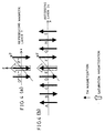
- the recording medium 9 has an arrangement in which a transparent dielectric layer 25, recording layer 24, and transparent dielectric layer 23 are deposited on a glass or plastic substrate 26. Recording is made on the recording layer 24, as indicated by the black arrow, and each region confining the black arrow makes up a magnetic domain (portion which is schematically parted to include the shortest recording mark).
- the recording layer 24 employs TbFeCo, which is widely used in magneto-optical recording media.
- TbFeCo is an amorphous alloy of FeCo as a transition metal ("TM” hereinafter) and Tb as a rare earth metal (“RE” hereinafter).
- TM transition metal
- RE rare earth metal
- TbFeCo is a ferri magnetic material in which TM magnetization and RE magnetization are coupled anti-parallel to each other (directions of respective sub-lattice magnetization are opposite).
- black arrow indicates TM magnetization
- blank arrow indicates saturation magnetization Ms, which is the difference of TM magnetization and RE magnetization. Note that, in a ferro magnetic material such as NdFeCo, the magnetization of each atom is coupled in parallel.
- the TbFeCo as used herein has temperature dependency for saturation magnetization Ms as shown in Fig. 3. Since room temperature (R.T.) makes up the compensation temperature, saturation magnetization Ms at room temperature is 0.
- compensation temperature refers to a temperature at which intensities of RE sub-lattice magnetization and TM sub-lattice magnetization become equal, and thus it is the temperature at which the apparent saturation magnetization Ms becomes 0, and the intensities of RE sub-lattice magnetization and TM sub-lattice magnetization are reversed at the temperatures around the compensation temperature.
- saturation magnetization Ms takes the maximum value at 150°C, and the Curie temperature (temperature at which magnetization disappears) occurs at 260°C.
- irradiation of recording layer 24 through reproducing magnetic layer 7 by the light beam 10b causes the reproducing layer 24 to generate a temperature distribution as shown in Fig. 2.
- the temperature raised portion of the recording layer 24 comes to have large saturation magnetization Ms, whereas in a region of lower temperature, saturation magnetization Ms becomes smaller and reaches 0 at around room temperature.
- a temperature raised portion can be made smaller than the beam spot diameter ⁇ , and the saturation magnetization Ms which occurs in the temperature raised portion generates magnetic flux.
- the information of saturation magnetization Ms, in the region of the recording layer 24 which is smaller than the beam spot diameter ⁇ is transferred as magnetic flux to the reproducing magnetic layer 7.
- the reproducing magnetic layer 7 has the same property as that of the reproducing layer 63 (see Fig. 13). Namely, the reproducing magnetic layer 7 is made of an alloy of rare earth metal and transition metal (RE-TM). Further, in the low temperature (room temperature) portion of the reproducing magnetic layer 7, TM magnetization and saturation magnetization are directed within the plane of the reproducing magnetic layer 7, and because the composition of the reproducing magnetic layer 7 is RE rich (sub-lattice magnetic moment of rare earth metal at room temperature exceeds sub-lattice magnetic moment of transition metal), saturation magnetization and TM magnetization are found in opposite directions. The directions of saturation magnetization are aligned in accordance with the magnetic flux from the recording layer 24 by being heated by a light beam.
- RE-TM rare earth metal and transition metal
- the diameter of the reproducing magnetic layer 7 is larger than the beam spot diameter ⁇ . Since the directions of magnetization of the reproducing magnetic layer 7 are aligned over the entire layer in accordance with the magnetic flux from the recording layer 24, the information of recording mark 27 is transferred to the region which is larger than the beam spot diameter ⁇ , and the region plays a part in reproduction, thus ensuring that the amplitude of a reproduced signal is not reduced even when the recording mark 27 is reduced, thereby improving recording density.
- the magneto-optical head of the present invention includes reproducing magnetic layer 7 which is preferably provided to be larger than the recording mark 27 recorded on the recording medium 9.
- the directions of magnetization in an area larger than recording mark 27 are aligned in accordance with the magnetic flux from the recording mark 27, thus increasing the area of a region which reflects incident light by rotating the polarization direction of the light in accordance with the information of the recording mark 27.
- the quantity of the reflected light containing information of the recording mark 27 is increased, and the reproduced signal amplitude can be made larger, thus realizing stable reproduction even when recording mark 27 is reduced.
- Light ray 10 from laser diode (light source) 1 reaches the recording layer 24 (see Fig. 2) of the recording medium 9 by travelling through collimator lens 2, relay lenses 51 and 52, PBS 3, stand-up mirror 53, objective lens 5, and auxiliary lens 6.
- the recording layer 24 of the recording medium 9 is provided more toward the upper surface of the recording medium 9 (toward the side where auxiliary lens 6 is provided) so as to allow the magneto-optical head to carry out recording and reproducing of information more effectively.
- the light reflected at the reproducing magnetic layer 7 and the recording medium 9 is incident on the Wollaston prism 4 through PBS 3.
- the reflected light from the recording medium 9 is separated into two polarization components (P polarized light and S polarized light) which oscillate orthogonal to each other, and thus the Wollaston prism 4 acts as an analyzer.
- the two polarization components emerge from the Wollaston prism 4 at a separation angle (1 to several degree with the wavelength of LD of 635 nm).
- the reflected light emerged from the Wollaston prism 4 then passes through the multi lens 11 having a sufficiently wide incident plane with respect to the light beam, and the two light beams, while being converged, are incident on a photodetector 12 which is divided into two sections, respectively corresponding to the two light beams.
- the recording medium 9 is rotated by a spindle motor 55, and the direction of the rotation is perpendicular to the plane of the paper.
- Table 56 mounting the stand-up mirror 53, and support cylinder 58 securing objective lens 5 and auxiliary lens 6 are linked to each other by spring (gimbal) 57, and the auxiliary lens 6 travels over the recording medium 9, floating thereon.
- the angle of objective lens 5 is adjusted such that the parallel rays 10a are converged on the reproducing magnetic layer 7 of the auxiliary lens 6 when incident on the objective lens 5, and the angle thus adjusted is fixed by the support cylinder 58.
- the table 56 mounting the stand-up mirror 53 is moved in the radial direction of the disk (recording medium 9) by a shaft 59.
- the optical system of the present embodiment is composed of (A) fixed optical system F which includes light source (LD) 1, PBS 3, Wollaston prism 4, and photodetector 12, etc., and (B) mobile optical system M which includes stand-up mirror 53 provided on table 56, objective lens 5, and auxiliary lens 6, etc.
- a fixed optical system F which includes light source (LD) 1, PBS 3, Wollaston prism 4, and photodetector 12, etc.
- B) mobile optical system M which includes stand-up mirror 53 provided on table 56, objective lens 5, and auxiliary lens 6, etc.
- tracking may be carried out first by moving the table 56 mounting the stand-up mirror 53 along the shaft 59, and thereafter by driving the relay lens 52 by an actuator (driving means) 44 so as to control the relay lens 52 in a direction of the arrow d (parallel to the plane of the paper).
- This method has the advantage of speed over the case where tracking control is carried out by driving by the actuator (not shown) the support cylinder 58 on which the objective lens 5, auxiliary lens 6, and recording coil 8 are fixed because the only driving load in this method is the relay lens 52.
- whether to drive the support cylinder 58, or to drive the relay lens 52 is determined based on the eccentricity of the recording medium 9 to be used.
- tracking control is made by moving the relay lens 52.
- the same effect can be obtained by moving the collimator lens 2 in a direction of the arrow d in Fig. 5.
- the relay lenses 51 and 52 are not particularly required.
- focusing and tracking control are to be carried out by moving the collimator lens 2
- a difficulty arises in alignment of the other optical system.
- the positioning relationship of the two is fixed by an adhesive, etc., and the position adjustment of various optical systems is made with the use of the collimated light, and focusing and tracking control are carried out by the positioning control of the relay lens 52.
- the relay lens 52 is moved in a direction of the arrow c (parallel to optical axis). That is, when the relay lens 52 is at a ready position, the light emerging from the relay lens 52 takes the form of collimated light, and it is focused on a predetermined focusing point by the objective lens 5 and relay lens 6. Meanwhile, when the relay lens 52 is moved back and forth from the ready position, the light emerging from the relay lens 52 takes the form of converged light or diffused light, and accordingly the focusing point of the light by the objective lens 5 and auxiliary lens 6 is shifted from the predetermined position in respective directions. Focusing control is carried out by this operation.
- control means 42 The various types of described control are carried out by a controller (control means) 42.
- a control program is stored beforehand in a non-volatile memory, etc.
- the magneto-optical device of the present invention preferably includes: a mobile optical system M which includes the described magneto-optical head; a fixed optical system F which includes a laser diode 1 for emitting light, a relay lens 52 provided on an optical axis, an actuator 44 for changing a position of the relay lens 52 with respect to the optical axis, and a photodetector 12 for receiving reflected light which includes information which is generated from projection of the light on the recording layer 24; and a controller 42 for controlling a projection position of the light on the recording medium 9, in which the controller carries out positional control of the relay lens 52 by driving the actuator 44 when a target position of the light is within a domain of the reproducing magnetic layer 7, and the controller carries out positional control of the mobile optical system M when a target position of the light is outside of the domain of the reproducing magnetic layer 7.
- the recording mark of the recording layer (see Fig. 2) can be transferred to the reproducing magnetic layer 7 upon magnification, and thus it is possible to prevent the amplitude of a reproduced signal from being reduced even when reproducing a small recording mark. As a result, high density recording and reproducing can be realized.
- the reproducing magnetic layer 7 of the auxiliary lens 6, and the transparent dielectric media 21 and 22 are designed with a material and thickness which would increase the Kerr rotation angle of the reproduced light, and they are selected to bring the recording layer 24 and reproducing magnetic layer 7 as close as possible so that the magnetic flux generated from the recording layer 24 is easily transferred.
- the material and thickness of these elements are not just limited to the specified ones used in the present embodiment.
- recording of information can be made by inputting a modulation signal based on the information to the coil 8 simultaneously with the laser projection.
- This method is equivalent to the conventional recording method on the magneto-optical disk. Specifically, recording is made by projecting light ray 10 from the light source 1 on the recording medium 9 through the auxiliary lens 6 to raise the temperature of the recording layer 24 to the temperature in the vicinity of the Curie temperature, and by applying an external magnetic field by the coil 8 to the portion of the recording layer at which the coercive force has decreased.
- the magneto-optical head of the present invention preferably includes a coil 8 which generates, at the time of recording information, magnetic flux which is in accordance with information to be recorded, and which is provided around the auxiliary lens 6.
- recording (writing) of information on the recording medium 9 can be made by applying a magnetic field of a direction in accordance with the information to be recorded with the use of the coil 8, wherein the magnetic field is applied under the condition where the temperature of a portion of the recording layer 24, which portion is to include a recording mark is raised to a temperature at which the coercive force is sufficiently reduced by increasing the energy of the light to be projected on the recording layer 24.
- recording and reproducing of information can be made with higher density than the conventional example with the use of a single magneto-optical head.
- Fig. 6 shows a relationship between reproduced signal amplitude and mark length of a recording mark, which compares the case where an MSR recording medium 9' (see Fig. 12 to be mentioned later) is reproduced by the conventional SIL and the case where an MSR recording medium 9 is reproduced by a non-MSR SIL utilizing MSR of the present invention.
- the beam spot diameter ⁇ is 0.6 ⁇ m
- the diameter of the reproducing magnetic layer 7 (see Fig. 2) of the MSR SIL is 0.8 ⁇ m.
- the reproduced signal amplitude is normalized by the amplitude which was used to reproduce the recording mark of 0.6 ⁇ m. It can be seen that with the use of the MSR SIL of the present invention, smaller recording marks can be reproduced.
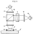
- the conventional SIL optical system as used in this comparison is as shown in Fig. 11, and except for the auxiliary lens 6', which is not provided with the reproducing magnetic layer 7, the arrangement thereof is the same as that of Fig. 1. Also, the other optical elements used are also the same as those shown in Fig. 1 and they are given the same reference numerals.
- Fig. 12 shows an arrangement of the recording medium 9' which was used in the experiment to reproduce the MSR recording medium by the conventional SIL, and also the arrangement of auxiliary lens 6'.
- transparent dielectric layer 114 On glass substrate 115, there are provided transparent dielectric layer 114, recording layer 113, transparent dielectric layer 112, reproducing layer 111, and transparent dielectric layer 110.
- the material and thickness of each layer are as follows: transparent dielectric layer 114, made of AlN in 40 nm; recording layer 113, made of TbFeCo in 40 nm; transparent dielectric layer 112, made of AlN in 10 nm; reproducing layer 111, made of GdFeCo in 40 nm; and transparent dielectric layer 110, made of AlN in 30 nm.
- Fig. 7 shows an arrangement of the recording medium 9 used in the experiment of reproducing the non-MSR medium by the MSR SIL of the present invention, and also the arrangement of auxiliary lens 6.
- Fig. 7 is a simplification of Fig. 2, and shows that transparent dielectric layer 25, recording layer 24, and transparent dielectric layer 23 are deposited on a plastic substrate 26.
- the transparent dielectric layer 25 is made of AlN in 20 nm
- the recording layer 24 is made of TbFeCo in 40 nm
- the transparent dielectric layer 23 is made of AlN in 10 nm.
- Indicated by "7" is a reproducing magnetic layer, and it is provided on the auxiliary lens 6. With this arrangement, information is reproduced by transferring the recording mark which is recorded on the recording layer 24 of the recording medium 9, onto the reproducing magnetic layer 7 which is integrally provided on the auxiliary lens 6 on the side of the recording medium 9.
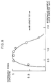
- Fig. 8 is a graph which shows the relationship between the diameter of the reproducing magnetic layer 7 of the auxiliary lens 6 and the reproduced signal amplitude of a recording mark of 0.1 ⁇ m. The curve is normalized by the reproduced signal amplitude when the diameter of the reproduced signal amplitude 7 was at 0.8 ⁇ m.
- the diameter of the reproducing magnetic layer 7 exceeds 1.5 ⁇ m, as noted in Fig. 14, a transfer mark is reduced and almost no mark is transferred.
- the diameter of the reproducing magnetic layer 7 becomes 1.5 ⁇ m or less, the force acting to reduce the transfer mark weakens gradually and transfer begins. As the diameter is further reduced, the transfer mark becomes larger. At the diameter of around 0.8 ⁇ m, the recording mark is completely transferred onto the reproducing magnetic layer 7.
- the diameter of the reproducing magnetic layer 7 is further reduced to 0.5 ⁇ m or less, the diameter of the reproducing magnetic layer 7 becomes smaller than the beam spot diameter ⁇ , and the quantity of the light associated with reproduction starts to decrease. Accordingly, in such a region, the reproduced signal amplitude becomes smaller.
- the diameter of the reproducing magnetic layer 7 is nearly the same or larger than the beam spot diameter ⁇ , and not more than 10 times the size (diameter) of the recording mark.
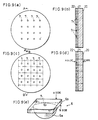
- a flat glass substrate having a refractive index of 1.5 transparent substrate 20
- AlN is deposited as transparent dielectric medium 21 in a thickness of 30 nm by sputtering.
- GdFeCo is deposited as reproducing magnetic layer 7 in a thickness of 40 nm in a disk shape with the diameter of 0.8 ⁇ m, and after removing the mask, AlN is deposited again in 10 ⁇ m as the transparent dielectric medium 22.
- the substrate is cut to obtain transparent element 6b, which makes up a portion of the auxiliary lens 6 of the MSR SIL.
- the A side of the transparent element 6b faces the medium, and, as shown in Fig. 9(e), to the B side of the transparent element 6b is attached spherical lens 6a having a refractive index of 1.5.
- a resin, etc. having the same or nearly the same refractive index (here, around 1.5) as that of the spherical lens 6a and transparent element 6b to paste the two elements, unwanted reflection, etc., can be prevented.
- the auxiliary lens 6 of the MSR SIL is obtained in this manner.
- coil 8 for generating a recording magnetic field is provided around the auxiliary lens 6.
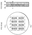
- coil 8 is provided within the auxiliary lens 6.
- Figs. 10(a) and 10(b) show the manufacturing method. Namely, after providing coil 8 on the glass substrate (transparent substrate 20) by wafer process, transparent dielectric medium 21, reproducing magnetic layer 7, and transparent dielectric medium 22 are provided. Thereafter, as with Fig. 9(c), the substrate is cut, and as with Fig. 9(e), the substrate is attached to the spherical lens 6a to obtain auxiliary lens 6. The same effect as that of Example 1 was obtained with the auxiliary lens 6 as manufactured in this manner.
Landscapes
- Physics & Mathematics (AREA)
- Engineering & Computer Science (AREA)
- Optics & Photonics (AREA)
- Chemical & Material Sciences (AREA)
- Nanotechnology (AREA)
- Mathematical Physics (AREA)
- Theoretical Computer Science (AREA)
- Crystallography & Structural Chemistry (AREA)
- Optical Head (AREA)
Applications Claiming Priority (2)
| Application Number | Priority Date | Filing Date | Title |
|---|---|---|---|
| JP4895699 | 1999-02-25 | ||
| JP04895699A JP3519304B2 (ja) | 1999-02-25 | 1999-02-25 | 光磁気ヘッド、光磁気装置及び光磁気記録再生方法 |
Publications (2)
| Publication Number | Publication Date |
|---|---|
| EP1031976A2 true EP1031976A2 (de) | 2000-08-30 |
| EP1031976A3 EP1031976A3 (de) | 2001-07-18 |
Family
ID=12817739
Family Applications (1)
| Application Number | Title | Priority Date | Filing Date |
|---|---|---|---|
| EP00103918A Withdrawn EP1031976A3 (de) | 1999-02-25 | 2000-02-24 | Magneto-optischer Kopf, magneto-optische Vorrichtung und magneto-optisches Aufzeichnungs- Wiedergabeverfahren |
Country Status (4)
| Country | Link |
|---|---|
| US (1) | US6396775B1 (de) |
| EP (1) | EP1031976A3 (de) |
| JP (1) | JP3519304B2 (de) |
| KR (1) | KR100323018B1 (de) |
Cited By (3)
| Publication number | Priority date | Publication date | Assignee | Title |
|---|---|---|---|---|
| EP1437719A3 (de) * | 2002-11-25 | 2007-03-07 | Sony Corporation | Optische Abtastvorrichtung, Aufzeichnungs-/Wiedergabegerät und Verfahren zur Erfassung des Nahfeldspalts |
| EP1488416A4 (de) * | 2002-02-25 | 2008-04-16 | Tae-Sun Song | Optische abnehmervorrichtung mit der fähigkeit zur kompensation von dickeabweichungen optischer aufzeichnungsmedien |
| CN105278115A (zh) * | 2015-08-05 | 2016-01-27 | 中国科学院光电研究院 | 激光器的光路调试装置及系统 |
Families Citing this family (6)
| Publication number | Priority date | Publication date | Assignee | Title |
|---|---|---|---|---|
| JP4230087B2 (ja) * | 1999-03-29 | 2009-02-25 | 独立行政法人産業技術総合研究所 | 光学再生記録方法および光学装置 |
| JP4157265B2 (ja) * | 2000-10-03 | 2008-10-01 | パイオニア株式会社 | レーザ光強度制御装置 |
| JP2003016620A (ja) * | 2001-06-29 | 2003-01-17 | Toshiba Corp | 磁気記録媒体、磁気記録装置および磁気記録方法 |
| JP3513125B2 (ja) * | 2001-07-27 | 2004-03-31 | 株式会社東芝 | 光ヘッドおよび光ディスク装置 |
| US20030067860A1 (en) * | 2001-10-10 | 2003-04-10 | Industrial Technology Research Institute | Near-field optical flying head |
| US20060023611A1 (en) * | 2004-07-23 | 2006-02-02 | Mika Wachi | Compound optical element and optical pickup apparatus |
Family Cites Families (6)
| Publication number | Priority date | Publication date | Assignee | Title |
|---|---|---|---|---|
| JPS6025037A (ja) * | 1983-07-20 | 1985-02-07 | Shiro Okamura | 磁気記録再生装置 |
| US5808973A (en) * | 1995-09-06 | 1998-09-15 | Kabushiki Kaisha Toshiba | Near field recording and reproducing apparatus |
| US6270696B1 (en) * | 1996-06-03 | 2001-08-07 | Terastor Corporation | Method of fabricating and integrating an optical assembly into a flying head |
| US6243350B1 (en) * | 1996-05-01 | 2001-06-05 | Terastor Corporation | Optical storage systems with flying optical heads for near-field recording and reading |
| EP0979508A4 (de) * | 1997-04-29 | 2001-10-24 | Terastor Corp | Elektrooptisches speichersystem mit fliegendem kopf für nahfeldaufzeichnung und wiedergabe |
| DE69829740T2 (de) * | 1997-10-06 | 2006-03-02 | Koninklijke Philips Electronics N.V. | Gerät zum informationslesen und /oder -schreiben von einem und auf ein aufnahmemedium |
-
1999
- 1999-02-25 JP JP04895699A patent/JP3519304B2/ja not_active Expired - Fee Related
-
2000
- 2000-02-24 EP EP00103918A patent/EP1031976A3/de not_active Withdrawn
- 2000-02-24 KR KR1020000008940A patent/KR100323018B1/ko not_active Expired - Fee Related
- 2000-02-25 US US09/513,827 patent/US6396775B1/en not_active Expired - Fee Related
Cited By (7)
| Publication number | Priority date | Publication date | Assignee | Title |
|---|---|---|---|---|
| EP1488416A4 (de) * | 2002-02-25 | 2008-04-16 | Tae-Sun Song | Optische abnehmervorrichtung mit der fähigkeit zur kompensation von dickeabweichungen optischer aufzeichnungsmedien |
| US7483345B2 (en) | 2002-02-25 | 2009-01-27 | Tae-Sun Song | Optical pickup apparatus capable of compensating thickness deviation of optical recording media |
| EP1437719A3 (de) * | 2002-11-25 | 2007-03-07 | Sony Corporation | Optische Abtastvorrichtung, Aufzeichnungs-/Wiedergabegerät und Verfahren zur Erfassung des Nahfeldspalts |
| US7230902B2 (en) | 2002-11-25 | 2007-06-12 | Sony Corporation | Optical pickup device, recording and reproducing apparatus and gap detection method |
| US7414947B2 (en) | 2002-11-25 | 2008-08-19 | Sony Corporation | Optical pickup device, recording and reproducing apparatus and gap detection method |
| CN105278115A (zh) * | 2015-08-05 | 2016-01-27 | 中国科学院光电研究院 | 激光器的光路调试装置及系统 |
| CN105278115B (zh) * | 2015-08-05 | 2020-04-07 | 中国科学院光电研究院 | 激光器的光路调试装置及系统 |
Also Published As
| Publication number | Publication date |
|---|---|
| JP2000251341A (ja) | 2000-09-14 |
| KR20000058165A (ko) | 2000-09-25 |
| JP3519304B2 (ja) | 2004-04-12 |
| US6396775B1 (en) | 2002-05-28 |
| KR100323018B1 (ko) | 2002-02-09 |
| EP1031976A3 (de) | 2001-07-18 |
Similar Documents
| Publication | Publication Date | Title |
|---|---|---|
| US5295122A (en) | Flying head of a magneto-optical recording apparatus | |
| KR960016891B1 (ko) | 광자기기록방식 | |
| US5233578A (en) | Method of recording information on a recording medium having at least two magnetic layers | |
| WO1998018122A1 (en) | Magneto-optic recording system and method | |
| JPH11134732A (ja) | 情報記録再生方法 | |
| US6396775B1 (en) | Magneto-optical device and recording/reproducing method | |
| EP0994466A2 (de) | Magneto-optische Kopfvorrichtung mit integrierter Hilfslinse und magneto-optischer Wiedergabekopf und die magneto-optische Kopfvorrichtung benutzende Aufzeichnungs - und Wiedergabevorrichtung | |
| JP2861188B2 (ja) | 光磁気記録再生装置 | |
| CA2048583C (en) | Magnetic recording and reproducing apparatus | |
| WO1998009280A1 (en) | Single-frequency laser source for optical data storage system | |
| JP2706292B2 (ja) | 光磁気記録装置 | |
| JP3333389B2 (ja) | 光磁気情報記憶媒体およびその再生方法 | |
| JP2000132880A (ja) | 情報再生素子及びそれを備える情報記録/再生ヘッド並びに情報再生方法 | |
| JP2883101B2 (ja) | 情報記録装置 | |
| JP2946489B2 (ja) | 情報記録再生装置 | |
| EP0510758A2 (de) | Verfahren zum thermomagnetischen Aufzeichnen und optischen Auslesen von Information | |
| JP2002032941A (ja) | ヘッド位置調整方法及び記録再生装置 | |
| JPS60150202A (ja) | 再生方法および装置 | |
| JPH08227542A (ja) | 磁気光学記録再生装置 | |
| JPH0219540B2 (de) | ||
| JPH11191247A (ja) | 光ピックアップ、光磁気記録媒体および光磁気記録再生装置 | |
| JPH03198242A (ja) | 磁気光学記録再生装置 | |
| JPS58130458A (ja) | 情報記録再生装置 | |
| JPH0689478A (ja) | 垂直磁界の相対位置設定方法及びその方法に用いられる相対位置設定用光磁気ディスク | |
| JPH0194554A (ja) | 光磁気記録媒体及びそれを用いる記録再生方法 |
Legal Events
| Date | Code | Title | Description |
|---|---|---|---|
| PUAI | Public reference made under article 153(3) epc to a published international application that has entered the european phase |
Free format text: ORIGINAL CODE: 0009012 |
|
| AK | Designated contracting states |
Kind code of ref document: A2 Designated state(s): AT BE CH LI Kind code of ref document: A2 Designated state(s): DE GB NL |
|
| AX | Request for extension of the european patent |
Free format text: AL;LT;LV;MK;RO;SI |
|
| PUAL | Search report despatched |
Free format text: ORIGINAL CODE: 0009013 |
|
| AK | Designated contracting states |
Kind code of ref document: A3 Designated state(s): AT BE CH CY DE DK ES FI FR GB GR IE IT LI LU MC NL PT SE |
|
| AX | Request for extension of the european patent |
Free format text: AL;LT;LV;MK;RO;SI |
|
| 17P | Request for examination filed |
Effective date: 20011022 |
|
| AKX | Designation fees paid |
Free format text: AT BE CH LI |
|
| REG | Reference to a national code |
Ref country code: DE Ref legal event code: 8566 |
|
| RBV | Designated contracting states (corrected) |
Designated state(s): DE GB NL |
|
| 17Q | First examination report despatched |
Effective date: 20050318 |
|
| STAA | Information on the status of an ep patent application or granted ep patent |
Free format text: STATUS: THE APPLICATION IS DEEMED TO BE WITHDRAWN |
|
| 18D | Application deemed to be withdrawn |
Effective date: 20050729 |