EP1032047B9 - Dispositif semiconducteur et convertisseur de puissance l'utilisant - Google Patents
Dispositif semiconducteur et convertisseur de puissance l'utilisant Download PDFInfo
- Publication number
- EP1032047B9 EP1032047B9 EP00301097A EP00301097A EP1032047B9 EP 1032047 B9 EP1032047 B9 EP 1032047B9 EP 00301097 A EP00301097 A EP 00301097A EP 00301097 A EP00301097 A EP 00301097A EP 1032047 B9 EP1032047 B9 EP 1032047B9
- Authority
- EP
- European Patent Office
- Prior art keywords
- semiconductor layer
- area
- type
- layer
- gates
- Prior art date
- Legal status (The legal status is an assumption and is not a legal conclusion. Google has not performed a legal analysis and makes no representation as to the accuracy of the status listed.)
- Expired - Lifetime
Links
Images






Classifications
-
- H—ELECTRICITY
- H10—SEMICONDUCTOR DEVICES; ELECTRIC SOLID-STATE DEVICES NOT OTHERWISE PROVIDED FOR
- H10D—INORGANIC ELECTRIC SEMICONDUCTOR DEVICES
- H10D62/00—Semiconductor bodies, or regions thereof, of devices having potential barriers
- H10D62/10—Shapes, relative sizes or dispositions of the regions of the semiconductor bodies; Shapes of the semiconductor bodies
- H10D62/102—Constructional design considerations for preventing surface leakage or controlling electric field concentration
- H10D62/103—Constructional design considerations for preventing surface leakage or controlling electric field concentration for increasing or controlling the breakdown voltage of reverse-biased devices
- H10D62/105—Constructional design considerations for preventing surface leakage or controlling electric field concentration for increasing or controlling the breakdown voltage of reverse-biased devices by having particular doping profiles, shapes or arrangements of PN junctions; by having supplementary regions, e.g. junction termination extension [JTE]
- H10D62/106—Constructional design considerations for preventing surface leakage or controlling electric field concentration for increasing or controlling the breakdown voltage of reverse-biased devices by having particular doping profiles, shapes or arrangements of PN junctions; by having supplementary regions, e.g. junction termination extension [JTE] having supplementary regions doped oppositely to or in rectifying contact with regions of the semiconductor bodies, e.g. guard rings with PN or Schottky junctions
-
- H—ELECTRICITY
- H10—SEMICONDUCTOR DEVICES; ELECTRIC SOLID-STATE DEVICES NOT OTHERWISE PROVIDED FOR
- H10D—INORGANIC ELECTRIC SEMICONDUCTOR DEVICES
- H10D12/00—Bipolar devices controlled by the field effect, e.g. insulated-gate bipolar transistors [IGBT]
- H10D12/411—Insulated-gate bipolar transistors [IGBT]
- H10D12/441—Vertical IGBTs
- H10D12/461—Vertical IGBTs having non-planar surfaces, e.g. having trenches, recesses or pillars in the surfaces of the emitter, base or collector regions
- H10D12/481—Vertical IGBTs having non-planar surfaces, e.g. having trenches, recesses or pillars in the surfaces of the emitter, base or collector regions having gate structures on slanted surfaces, on vertical surfaces, or in grooves, e.g. trench gate IGBTs
-
- H—ELECTRICITY
- H10—SEMICONDUCTOR DEVICES; ELECTRIC SOLID-STATE DEVICES NOT OTHERWISE PROVIDED FOR
- H10D—INORGANIC ELECTRIC SEMICONDUCTOR DEVICES
- H10D62/00—Semiconductor bodies, or regions thereof, of devices having potential barriers
- H10D62/10—Shapes, relative sizes or dispositions of the regions of the semiconductor bodies; Shapes of the semiconductor bodies
- H10D62/124—Shapes, relative sizes or dispositions of the regions of semiconductor bodies or of junctions between the regions
- H10D62/126—Top-view geometrical layouts of the regions or the junctions
-
- H—ELECTRICITY
- H10—SEMICONDUCTOR DEVICES; ELECTRIC SOLID-STATE DEVICES NOT OTHERWISE PROVIDED FOR
- H10D—INORGANIC ELECTRIC SEMICONDUCTOR DEVICES
- H10D62/00—Semiconductor bodies, or regions thereof, of devices having potential barriers
- H10D62/10—Shapes, relative sizes or dispositions of the regions of the semiconductor bodies; Shapes of the semiconductor bodies
- H10D62/17—Semiconductor regions connected to electrodes not carrying current to be rectified, amplified or switched, e.g. channel regions
- H10D62/393—Body regions of DMOS transistors or IGBTs
Definitions
- the structure using trench insulating gates is described in Japanese Patent Application Laid-Open 5-243561 .
- This is a structure that the injection effect of holes into the n-type base layer is increased.
- the trench insulating gate type IGBT having trench insulating gates formed at equal intervals or widely, the number of channels formed on the side walls of the trench insulating gates are reduced and the channel width is narrowed.
- the p-type base layer which is positioned on the other surface on the side where no channels are formed is covered with an insulating film and isolated from the main electrode. It is said that this structure increases the injection effect and provides a conductivity modulation close to that of the thyristor.
- EP 0 746 030 describes a trench-gated power MOSFET device defining a plurality of MOSFET cells. A protective diffusion in the form of a diode is constructed, the diode being connected in parallel with the channel region in each of the MOSFET cells.
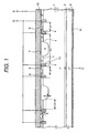
- the withstand voltage is held by junction of the n-type base layer 1 and the p-type base layer 4. Since the trench insulating gates 7 are projected into the n-type base layer 1, the electric field intensity is high at the corner of the trench insulating gates 7.
- Lb > La the electric field intensity is high in the area Lb.
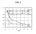
- the withstand voltage of the element is higher, to ensure sufficient loss reduction and short-circuit withstand amount, it is valid to widen the area Lb.
- the area Lb is widened so that the withstand voltage of the element is decided by the electric field intensity in the area Lb, the withstand voltage of the element is lowered.
- the upper limit of the potential between the trench insulating gates 7 and the p-type base layer 4 positioned in the area Lb can be set and generation of an electrostatic concentration exceeding the withstand voltage of the insulating film 71 can be prevented.
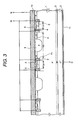
- holes in the n-type base layer 4 pass the p-type well layer 9 and flow into the main electrode 10. Therefore, holes in the n-type base layer 4 can be reduced and the turn-off loss can be reduced. Furthermore, since holes ejected from the n-type source layer 4 in the area La can be reduced, latch-up can be prevented.
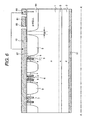
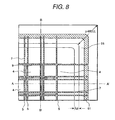
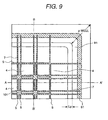
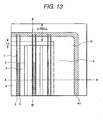
- Fig. 5 shows the fourth embodiment of the present invention and is a plan view of the cell and cell end of the trench insulating gate type IGBT relating to the first embodiment of the present invention.
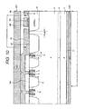
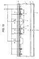
- Figs. 6 and 7 are cross sectional views of A-A' and B-B' shown in Fig. 5 respectively.
- the difference in the delay between a gate signal of the IGBT near to the gate electrode pad or gate input terminal and a gate signal of the IGBT far from it is made smaller, so that the uniformity of the switching operation in the element is improved. Therefore, the element destruction due to current concentration caused by an ununiform operation can be prevented.
- the insulating film 161 is formed thicker or higher than the gate wires 61 and the insulating film around them.
- the top of the main electrode 10 is formed higher than the metal wires 65 on the gate wires 61 and the emitter electrode member 231 is not in contact with the metal wires 65 on the gate wires. Since the metal wires 65 for reducing the gate wire resistance are provided, the delay of a gate signal to be transferred to the IGBT can be suppressed. Therefore, the switching delay between the IGBT unit near to the gate pad and the IGBT far from the gate pad is reduced and the current concentration to the IGBT units and heat destruction by it can be prevented.
- the trench insulating gates 7 are arranged so as to intersect each other. As indicated by this embodiment 1, the gate input capacity in this structure can be reduced and also the delay of a gate signal can be suppressed and by pressurizing the main electrodes 10 and 11, the emitter electrode and collector electrode can come into contact with each other.
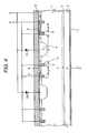
- the area La is divided into two areas by this groove. In these two areas, the n-type source layer 5 is formed respectively in the same way.
- the main electrode 10 (source electrode) is electrically connected to the n-type source layer 5 and the p-type base layer 4 in the same way as with Fig. 1 .
- the main electrode 10 (source electrode) is electrically connected to the n-type source layer 5 and the p-type base layer 4.
- the p+ layer 6 whose impurity density is higher than that of the p-type base layer 4 is formed and the p-type base layer 4 is electrically connected to the main electrode via the p+ layer 6.
Landscapes
- Thyristors (AREA)
- Semiconductor Integrated Circuits (AREA)
- Electrodes Of Semiconductors (AREA)
- Metal-Oxide And Bipolar Metal-Oxide Semiconductor Integrated Circuits (AREA)
Claims (10)
- transistor bipolaire à porte isolée comportant :une première couche semi-conductrice (2) d'un premier type de conductivité,une deuxième couche semi-conductrice (1) d'un second type de conductivité proche de ladite première couche semi-conductrice,une troisième couche serni-conduccrice (4) dudit premier type conducteur proche de ladite deuxième couche semi-conductrice,une pluralité de portés isolées (7) traversant ladite troisième couche semi-conductrice et atteignant ladite deuxième couche semi-conductrice,une première zone et une seconde zone qui sont des zones entre lesdites portes isolées voisines (7) et mutuellement proches,une quatrième couche semi-conductrice (5) dudit second type de conductivité en contact avec lesdites portes isolées (7) dans ladite troisième couche semi-conductrice (4) de ladite première zone,une première électrode principale (10) électriquement connectée à ladite troisième couche semi-conductrice (4) et à ladite quatrième couche semi- conductrice (5) dans ladite première zone, etune seconde électrode principale (;lui) électriquement connectée à ladite première couche semi-conductrice (2), caractérisé en ce que :en partant de l'hypothèse d'un intervalle entre lesdites portes isolées voisines (7) dans ladite première zone désigné en tant que La et d'un intervalle entre lesdites portes isolées voisines dans ladite seconde zone désigné en tant que Lb, La ≤ 5µm et Lb/La > 1, etune cinquième couche semi-conductrice (9) dudit premier type de conductivité soit(i) plus profonde que ladite troisième couche semi-conductrice (4) soit(ii) plus profonde que la partie inférieure desdites partes isolées (7)est installée dans ladite seconde zone, et ladite première électrode principale (10) est isolée de ladite cinquième couche semi-conductrice (9) par un film isolant.
- Transistor bipolaire à porte isolée selon la revendication 1, dans lequel 6 ≥ Lb/La ≥ 2.
- Transistor bipolaire à porte isolée selon la revendication 1 ou 2, dans lequel ladite troisième couche semi-conductrice dans ladite seconde zone et ladite première électrode sont isolées par un film isolant.
- Transistor bipolaire à porte isolée selon la revendication 3, dans lequel ladite troisième couche semi-conductrice dans ladite première zone et ladite troisième couche semi-conductrice dans ladite seconde zone sont séparées l'une de l'autre.
- Transistor dipolaire à porte isolée selon la revendication 1, dans lequel lesdites troisième couche semi-conductrice et cinquième couche semi-conductrice dans ladite seconde zone et ladite première électrode sont isolées par un film isolant.
- Transistor bipolaire à, porte isolée selon la revendication 5, dans lequel ladite troisième couche semi-conductrice dans ladite première zone et ladite troisième couche semi-cosrduatrice dans ladite seconde zone sont séparées l'une de l'autre.
- Transistor bipolaire à porte isolée selon la revendication 1, dans lequel une diode Zener est connectée entre ladite cinquième couche semi-conductrice et ladite première électrode principale.
- Transistor bipolaire à porte isolée selon la revendication 1, dans lequel ladite deuxième couche semi-conductrice dans ladite première zone a une première partie de ladite première couche semi-conductrice et une seconde partie de ladite troisième couche semi-conductrice dont la densité d'impuretés est supérieure à celle de ladite première partie.
- Transistor bipolaire à porte isolée selon la revendication 1, dans lequel une diode Zener est connectée entre ladite troisième couche semi-conductrice dans ladite seconde zone et ladite première électrode principale.
- Transistor bipolaire à porte isolée selon la revendication 8 ou la revendication 9, dans lequel ladite troisième couche semi-conductrice dans ladite seconde zone et ladite première électrode sont isolées par un film isolant.
Priority Applications (2)
| Application Number | Priority Date | Filing Date | Title |
|---|---|---|---|
| EP07009037A EP1811572B1 (fr) | 1999-02-17 | 2000-02-11 | Dispositif à semi-conducteur et convertisseur de puissance utilisant ce même dispositif à semi-conducteur |
| EP10007172.9A EP2237319B1 (fr) | 1999-02-17 | 2000-02-11 | Dispositif semiconducteur et convertisseur de puissance l'utilisant |
Applications Claiming Priority (2)
| Application Number | Priority Date | Filing Date | Title |
|---|---|---|---|
| JP3816699 | 1999-02-17 | ||
| JP3816699 | 1999-02-17 |
Related Child Applications (4)
| Application Number | Title | Priority Date | Filing Date |
|---|---|---|---|
| EP10007172.9A Division EP2237319B1 (fr) | 1999-02-17 | 2000-02-11 | Dispositif semiconducteur et convertisseur de puissance l'utilisant |
| EP07009037A Division EP1811572B1 (fr) | 1999-02-17 | 2000-02-11 | Dispositif à semi-conducteur et convertisseur de puissance utilisant ce même dispositif à semi-conducteur |
| EP07009037.8 Division-Into | 2007-05-04 | ||
| EP10007172.9 Division-Into | 2010-07-12 |
Publications (4)
| Publication Number | Publication Date |
|---|---|
| EP1032047A2 EP1032047A2 (fr) | 2000-08-30 |
| EP1032047A3 EP1032047A3 (fr) | 2001-11-28 |
| EP1032047B1 EP1032047B1 (fr) | 2010-09-22 |
| EP1032047B9 true EP1032047B9 (fr) | 2011-02-09 |
Family
ID=12517825
Family Applications (3)
| Application Number | Title | Priority Date | Filing Date |
|---|---|---|---|
| EP07009037A Expired - Lifetime EP1811572B1 (fr) | 1999-02-17 | 2000-02-11 | Dispositif à semi-conducteur et convertisseur de puissance utilisant ce même dispositif à semi-conducteur |
| EP10007172.9A Expired - Lifetime EP2237319B1 (fr) | 1999-02-17 | 2000-02-11 | Dispositif semiconducteur et convertisseur de puissance l'utilisant |
| EP00301097A Expired - Lifetime EP1032047B9 (fr) | 1999-02-17 | 2000-02-11 | Dispositif semiconducteur et convertisseur de puissance l'utilisant |
Family Applications Before (2)
| Application Number | Title | Priority Date | Filing Date |
|---|---|---|---|
| EP07009037A Expired - Lifetime EP1811572B1 (fr) | 1999-02-17 | 2000-02-11 | Dispositif à semi-conducteur et convertisseur de puissance utilisant ce même dispositif à semi-conducteur |
| EP10007172.9A Expired - Lifetime EP2237319B1 (fr) | 1999-02-17 | 2000-02-11 | Dispositif semiconducteur et convertisseur de puissance l'utilisant |
Country Status (3)
| Country | Link |
|---|---|
| EP (3) | EP1811572B1 (fr) |
| KR (1) | KR100745557B1 (fr) |
| DE (1) | DE60044992D1 (fr) |
Families Citing this family (35)
| Publication number | Priority date | Publication date | Assignee | Title |
|---|---|---|---|---|
| JP2001168333A (ja) * | 1999-09-30 | 2001-06-22 | Toshiba Corp | トレンチゲート付き半導体装置 |
| US7301308B2 (en) | 2001-11-02 | 2007-11-27 | Aker Wade Power Technologies, Llc | Fast charger for high capacity batteries |
| EP1451921A4 (fr) * | 2001-11-02 | 2006-01-11 | Aker Wade Power Technologies L | Chargeur rapide pour batteries haute capacite |
| CN100472735C (zh) * | 2002-03-29 | 2009-03-25 | 费查尔德半导体有限公司 | 横向耗尽结构的场效应晶体管 |
| JP4085781B2 (ja) * | 2002-11-01 | 2008-05-14 | トヨタ自動車株式会社 | 電界効果型半導体装置 |
| JP4136778B2 (ja) * | 2003-05-07 | 2008-08-20 | 富士電機デバイステクノロジー株式会社 | 絶縁ゲート型バイポーラトランジスタ |
| JP4799829B2 (ja) * | 2003-08-27 | 2011-10-26 | 三菱電機株式会社 | 絶縁ゲート型トランジスタ及びインバータ回路 |
| JP4703138B2 (ja) * | 2004-06-18 | 2011-06-15 | 株式会社東芝 | 絶縁ゲート型半導体装置 |
| JP4731848B2 (ja) | 2004-07-16 | 2011-07-27 | 株式会社豊田中央研究所 | 半導体装置 |
| JP5017850B2 (ja) * | 2005-11-30 | 2012-09-05 | 株式会社日立製作所 | 電力用半導体装置およびそれを用いた電力変換装置 |
| JP5044950B2 (ja) | 2006-03-14 | 2012-10-10 | 株式会社デンソー | 半導体装置 |
| EP2003694B1 (fr) * | 2007-06-14 | 2011-11-23 | Denso Corporation | Dispositif semi-conducteur |
| JP5561922B2 (ja) | 2008-05-20 | 2014-07-30 | 三菱電機株式会社 | パワー半導体装置 |
| JP4644730B2 (ja) * | 2008-08-12 | 2011-03-02 | 株式会社日立製作所 | 半導体装置及びそれを用いた電力変換装置 |
| US8344480B2 (en) | 2008-09-30 | 2013-01-01 | Ixys Corporation | Insulated gate bipolar transistor |
| JP5423018B2 (ja) * | 2009-02-02 | 2014-02-19 | 三菱電機株式会社 | 半導体装置 |
| WO2011080928A1 (fr) * | 2010-01-04 | 2011-07-07 | 株式会社日立製作所 | Dispositif semi-conducteur et dispositif de conversion de puissance électrique l'utilisant |
| KR101840903B1 (ko) | 2011-07-07 | 2018-03-21 | 에이비비 슈바이쯔 아게 | 절연 게이트 바이폴라 트랜지스터 |
| JP6026528B2 (ja) * | 2011-07-14 | 2016-11-16 | アーベーベー・テヒノロギー・アーゲー | 絶縁ゲート型バイポーラトランジスタ |
| EP2787534B1 (fr) * | 2011-11-28 | 2020-09-23 | Fuji Electric Co., Ltd. | Dispositif semiconducteur à grille isolée et procédé de son fabrication |
| JP5973730B2 (ja) | 2012-01-05 | 2016-08-23 | ルネサスエレクトロニクス株式会社 | Ie型トレンチゲートigbt |
| KR101311538B1 (ko) * | 2012-01-19 | 2013-09-25 | 주식회사 케이이씨 | 전력 반도체 디바이스 및 그 제조 방법 |
| JP6072445B2 (ja) | 2012-06-28 | 2017-02-01 | 株式会社 日立パワーデバイス | 半導体装置およびそれを用いた電力変換装置 |
| US9595602B2 (en) | 2012-09-07 | 2017-03-14 | Hitachi, Ltd. | Switching device for power conversion and power conversion device |
| WO2016113865A1 (fr) * | 2015-01-14 | 2016-07-21 | 三菱電機株式会社 | Dispositif semiconducteur et son procédé de fabrication |
| JP6588363B2 (ja) | 2016-03-09 | 2019-10-09 | トヨタ自動車株式会社 | スイッチング素子 |
| JP6299789B2 (ja) | 2016-03-09 | 2018-03-28 | トヨタ自動車株式会社 | スイッチング素子 |
| JP6460016B2 (ja) | 2016-03-09 | 2019-01-30 | トヨタ自動車株式会社 | スイッチング素子 |
| JP6804379B2 (ja) * | 2017-04-24 | 2020-12-23 | 三菱電機株式会社 | 半導体装置 |
| CN107464839B (zh) * | 2017-08-17 | 2020-02-04 | 电子科技大学 | 一种防止关断失效的栅控晶闸管器件 |
| CN108493242B (zh) * | 2018-05-31 | 2020-08-28 | 电子科技大学 | 一种优化体内电场的载流子增强型igbt器件 |
| CN108767006B (zh) * | 2018-05-31 | 2020-09-15 | 电子科技大学 | 一种集成电压采样功能的igbt器件 |
| CN111384149B (zh) * | 2018-12-29 | 2021-05-14 | 比亚迪半导体股份有限公司 | 沟槽型igbt及其制备方法 |
| CN110416294B (zh) * | 2019-08-29 | 2021-01-08 | 电子科技大学 | 一种高耐压低损耗超结功率器件 |
| CN113793807B (zh) * | 2021-11-18 | 2022-02-11 | 南京华瑞微集成电路有限公司 | 一种集成源漏电容的超结mos器件及其制作方法 |
Family Cites Families (13)
| Publication number | Priority date | Publication date | Assignee | Title |
|---|---|---|---|---|
| US4712124A (en) * | 1986-12-22 | 1987-12-08 | North American Philips Corporation | Complementary lateral insulated gate rectifiers with matched "on" resistances |
| EP1469524A3 (fr) * | 1991-08-08 | 2005-07-06 | Kabushiki Kaisha Toshiba | Transistor semi-conducteur à grille isolée à tranchée |
| DE4407279C1 (de) * | 1994-03-04 | 1994-10-13 | Siemens Ag | Halbleiterbauelement für den Überspannungsschutz von MOSFET und IGBT |
| DE69432407D1 (de) * | 1994-05-19 | 2003-05-08 | Cons Ric Microelettronica | Integrierte Leistungsschaltung ("PIC") mit vertikalem IGB und Verfahren zur Herstellung derselben |
| JPH08116056A (ja) * | 1994-10-19 | 1996-05-07 | Hitachi Ltd | 電圧駆動型半導体装置及びそれを用いた電力変換装置 |
| EP0746030B1 (fr) | 1995-06-02 | 2001-11-21 | SILICONIX Incorporated | MOSFET de puissance à grille entranchée comprenant des diodes de protection anrrangées en un motif périodique |
| KR100187635B1 (ko) * | 1996-03-20 | 1999-07-01 | 김충환 | 단락 애노우드 수평형 절연 게이트 바이폴라 트랜지스터 |
| JP2776365B2 (ja) * | 1996-04-04 | 1998-07-16 | 日本電気株式会社 | 多段接続型半導体用キャリヤーとそれを用いた半導体装置、及びその製造方法 |
| KR100200366B1 (ko) * | 1996-10-31 | 1999-06-15 | 윤종용 | 절연 게이트 바이폴라 트랜지스터 |
| DE19705276A1 (de) | 1996-12-06 | 1998-08-20 | Semikron Elektronik Gmbh | IGBT mit Trench-Gate-Struktur |
| JPH118385A (ja) * | 1997-06-18 | 1999-01-12 | Hitachi Ltd | 内燃機関用点火装置およびigbt |
| DE19727676A1 (de) * | 1997-06-30 | 1999-01-07 | Asea Brown Boveri | MOS gesteuertes Leistungshalbleiterbauelement |
| US6110799A (en) * | 1997-06-30 | 2000-08-29 | Intersil Corporation | Trench contact process |
-
2000
- 2000-02-09 KR KR1020000005888A patent/KR100745557B1/ko not_active Expired - Lifetime
- 2000-02-11 EP EP07009037A patent/EP1811572B1/fr not_active Expired - Lifetime
- 2000-02-11 EP EP10007172.9A patent/EP2237319B1/fr not_active Expired - Lifetime
- 2000-02-11 EP EP00301097A patent/EP1032047B9/fr not_active Expired - Lifetime
- 2000-02-11 DE DE60044992T patent/DE60044992D1/de not_active Expired - Lifetime
Also Published As
| Publication number | Publication date |
|---|---|
| EP2237319B1 (fr) | 2015-04-08 |
| EP2237319A3 (fr) | 2010-10-27 |
| EP1811572B1 (fr) | 2012-05-30 |
| EP2237319A2 (fr) | 2010-10-06 |
| EP1811572A2 (fr) | 2007-07-25 |
| KR20000076628A (ko) | 2000-12-26 |
| DE60044992D1 (de) | 2010-11-04 |
| EP1032047B1 (fr) | 2010-09-22 |
| EP1811572A3 (fr) | 2007-09-19 |
| EP1032047A3 (fr) | 2001-11-28 |
| KR100745557B1 (ko) | 2007-08-02 |
| EP1032047A2 (fr) | 2000-08-30 |
Similar Documents
| Publication | Publication Date | Title |
|---|---|---|
| EP1032047B1 (fr) | Dispositif semiconducteur et convertisseur de puissance l'utilisant | |
| JP4310017B2 (ja) | 半導体装置及び電力変換装置 | |
| KR100398532B1 (ko) | 절연 게이트 트랜지스터 | |
| US8193578B2 (en) | Power supply circuit having a semiconductor device including a MOSFET and a Schottky junction | |
| KR100576303B1 (ko) | 절연게이트형 트랜지스터 | |
| JP5452195B2 (ja) | 半導体装置及びそれを用いた電力変換装置 | |
| US20070200138A1 (en) | Semiconductor device having IGBT and diode | |
| US6133607A (en) | Semiconductor device | |
| EP0526037B1 (fr) | Transistor bipolaire latéral à grille isolée et arrangement multiple correspondant | |
| JPH10178176A (ja) | トレンチ・ゲート構造を有するトレンチ・ゲート形絶縁ゲート・バイポーラ・トランジスタ | |
| KR0160953B1 (ko) | 횡형 절연 게이트 바이폴라 트랜지스터 | |
| EP0565350B1 (fr) | Dispositif à semiconducteur avec une couche tampon | |
| US6864535B2 (en) | Controllable semiconductor switching element that blocks in both directions | |
| JP2023130251A (ja) | 半導体装置 | |
| JP4829003B2 (ja) | 半導体装置及び電力変換装置 | |
| CN118073422A (zh) | 一种高抗性SiC VDMOSFET器件及其制备方法 | |
| KR102030466B1 (ko) | 레터럴 타입의 전력 반도체 소자 | |
| JPH1140818A (ja) | 半導体装置 | |
| JPH11214690A (ja) | 半導体素子および平型半導体装置 |
Legal Events
| Date | Code | Title | Description |
|---|---|---|---|
| PUAI | Public reference made under article 153(3) epc to a published international application that has entered the european phase |
Free format text: ORIGINAL CODE: 0009012 |
|
| 17P | Request for examination filed |
Effective date: 20000229 |
|
| AK | Designated contracting states |
Kind code of ref document: A2 Designated state(s): DE FR GB Kind code of ref document: A2 Designated state(s): AT BE CH CY DE DK ES FI FR GB GR IE IT LI LU MC NL PT SE |
|
| AX | Request for extension of the european patent |
Free format text: AL;LT;LV;MK;RO;SI |
|
| PUAL | Search report despatched |
Free format text: ORIGINAL CODE: 0009013 |
|
| AK | Designated contracting states |
Kind code of ref document: A3 Designated state(s): AT BE CH CY DE DK ES FI FR GB GR IE IT LI LU MC NL PT SE |
|
| AX | Request for extension of the european patent |
Free format text: AL;LT;LV;MK;RO;SI |
|
| AKX | Designation fees paid |
Free format text: DE FR GB |
|
| 17Q | First examination report despatched |
Effective date: 20061031 |
|
| GRAP | Despatch of communication of intention to grant a patent |
Free format text: ORIGINAL CODE: EPIDOSNIGR1 |
|
| GRAS | Grant fee paid |
Free format text: ORIGINAL CODE: EPIDOSNIGR3 |
|
| GRAA | (expected) grant |
Free format text: ORIGINAL CODE: 0009210 |
|
| AK | Designated contracting states |
Kind code of ref document: B1 Designated state(s): DE FR GB |
|
| REG | Reference to a national code |
Ref country code: GB Ref legal event code: FG4D |
|
| REF | Corresponds to: |
Ref document number: 60044992 Country of ref document: DE Date of ref document: 20101104 Kind code of ref document: P |
|
| PLBE | No opposition filed within time limit |
Free format text: ORIGINAL CODE: 0009261 |
|
| STAA | Information on the status of an ep patent application or granted ep patent |
Free format text: STATUS: NO OPPOSITION FILED WITHIN TIME LIMIT |
|
| 26N | No opposition filed |
Effective date: 20110623 |
|
| REG | Reference to a national code |
Ref country code: DE Ref legal event code: R097 Ref document number: 60044992 Country of ref document: DE Effective date: 20110623 |
|
| REG | Reference to a national code |
Ref country code: DE Ref legal event code: R082 Ref document number: 60044992 Country of ref document: DE Representative=s name: PATENTANWAELTE STREHL, SCHUEBEL-HOPF & PARTNER, DE |
|
| REG | Reference to a national code |
Ref country code: DE Ref legal event code: R081 Ref document number: 60044992 Country of ref document: DE Owner name: HITACHI POWER SEMICONDUCTOR DEVICE, LTD., HITA, JP Free format text: FORMER OWNER: HITACHI, LTD., TOKYO, JP Effective date: 20141127 Ref country code: DE Ref legal event code: R082 Ref document number: 60044992 Country of ref document: DE Representative=s name: PATENTANWAELTE STREHL, SCHUEBEL-HOPF & PARTNER, DE Effective date: 20141127 Ref country code: GB Ref legal event code: 732E Free format text: REGISTERED BETWEEN 20141204 AND 20141211 Ref country code: DE Ref legal event code: R082 Ref document number: 60044992 Country of ref document: DE Representative=s name: STREHL SCHUEBEL-HOPF & PARTNER MBB PATENTANWAE, DE Effective date: 20141127 |
|
| REG | Reference to a national code |
Ref country code: FR Ref legal event code: CA Effective date: 20141209 Ref country code: FR Ref legal event code: TP Owner name: HITACHI POWER SEMICONDUCTOR DEVICE, LTD., JP Effective date: 20141209 |
|
| REG | Reference to a national code |
Ref country code: FR Ref legal event code: PLFP Year of fee payment: 17 |
|
| REG | Reference to a national code |
Ref country code: FR Ref legal event code: PLFP Year of fee payment: 18 |
|
| REG | Reference to a national code |
Ref country code: FR Ref legal event code: PLFP Year of fee payment: 19 |
|
| PGFP | Annual fee paid to national office [announced via postgrant information from national office to epo] |
Ref country code: GB Payment date: 20190206 Year of fee payment: 20 Ref country code: FR Payment date: 20190111 Year of fee payment: 20 Ref country code: DE Payment date: 20190129 Year of fee payment: 20 |
|
| REG | Reference to a national code |
Ref country code: DE Ref legal event code: R071 Ref document number: 60044992 Country of ref document: DE |
|
| REG | Reference to a national code |
Ref country code: GB Ref legal event code: PE20 Expiry date: 20200210 |
|
| PG25 | Lapsed in a contracting state [announced via postgrant information from national office to epo] |
Ref country code: GB Free format text: LAPSE BECAUSE OF EXPIRATION OF PROTECTION Effective date: 20200210 |