EP1034064B1 - Verbesserte schleifmaschine - Google Patents
Verbesserte schleifmaschine Download PDFInfo
- Publication number
- EP1034064B1 EP1034064B1 EP98951580A EP98951580A EP1034064B1 EP 1034064 B1 EP1034064 B1 EP 1034064B1 EP 98951580 A EP98951580 A EP 98951580A EP 98951580 A EP98951580 A EP 98951580A EP 1034064 B1 EP1034064 B1 EP 1034064B1
- Authority
- EP
- European Patent Office
- Prior art keywords
- spindle
- machine
- spindles
- sensors
- axis
- Prior art date
- Legal status (The legal status is an assumption and is not a legal conclusion. Google has not performed a legal analysis and makes no representation as to the accuracy of the status listed.)
- Expired - Lifetime
Links
- 239000000523 sample Substances 0.000 claims description 30
- 230000009021 linear effect Effects 0.000 claims description 10
- 238000005259 measurement Methods 0.000 claims description 9
- 230000020347 spindle assembly Effects 0.000 claims description 8
- 230000008859 change Effects 0.000 claims description 7
- 238000006073 displacement reaction Methods 0.000 claims description 7
- 239000003607 modifier Substances 0.000 claims description 3
- 230000003252 repetitive effect Effects 0.000 claims description 2
- 230000000712 assembly Effects 0.000 description 3
- 238000000429 assembly Methods 0.000 description 3
- 238000000034 method Methods 0.000 description 3
- 230000008569 process Effects 0.000 description 3
- 241000238631 Hexapoda Species 0.000 description 1
- XUIMIQQOPSSXEZ-UHFFFAOYSA-N Silicon Chemical compound [Si] XUIMIQQOPSSXEZ-UHFFFAOYSA-N 0.000 description 1
- 239000011521 glass Substances 0.000 description 1
- 230000002706 hydrostatic effect Effects 0.000 description 1
- 230000001939 inductive effect Effects 0.000 description 1
- 230000007246 mechanism Effects 0.000 description 1
- 229920001277 pectin Polymers 0.000 description 1
- 230000009467 reduction Effects 0.000 description 1
- 230000004044 response Effects 0.000 description 1
- 229910052710 silicon Inorganic materials 0.000 description 1
- 239000010703 silicon Substances 0.000 description 1
- 235000012431 wafers Nutrition 0.000 description 1
Images


Classifications
-
- B—PERFORMING OPERATIONS; TRANSPORTING
- B24—GRINDING; POLISHING
- B24B—MACHINES, DEVICES, OR PROCESSES FOR GRINDING OR POLISHING; DRESSING OR CONDITIONING OF ABRADING SURFACES; FEEDING OF GRINDING, POLISHING, OR LAPPING AGENTS
- B24B27/00—Other grinding machines or devices
- B24B27/0084—Other grinding machines or devices the grinding wheel support being angularly adjustable
-
- B—PERFORMING OPERATIONS; TRANSPORTING
- B24—GRINDING; POLISHING
- B24B—MACHINES, DEVICES, OR PROCESSES FOR GRINDING OR POLISHING; DRESSING OR CONDITIONING OF ABRADING SURFACES; FEEDING OF GRINDING, POLISHING, OR LAPPING AGENTS
- B24B27/00—Other grinding machines or devices
- B24B27/0053—Radial grinding machines
-
- B—PERFORMING OPERATIONS; TRANSPORTING
- B24—GRINDING; POLISHING
- B24B—MACHINES, DEVICES, OR PROCESSES FOR GRINDING OR POLISHING; DRESSING OR CONDITIONING OF ABRADING SURFACES; FEEDING OF GRINDING, POLISHING, OR LAPPING AGENTS
- B24B41/00—Component parts such as frames, beds, carriages, headstocks
- B24B41/04—Headstocks; Working-spindles; Features relating thereto
- B24B41/047—Grinding heads for working on plane surfaces
-
- B—PERFORMING OPERATIONS; TRANSPORTING
- B24—GRINDING; POLISHING
- B24B—MACHINES, DEVICES, OR PROCESSES FOR GRINDING OR POLISHING; DRESSING OR CONDITIONING OF ABRADING SURFACES; FEEDING OF GRINDING, POLISHING, OR LAPPING AGENTS
- B24B47/00—Drives or gearings; Equipment therefor
- B24B47/22—Equipment for exact control of the position of the grinding tool or work at the start of the grinding operation
-
- B—PERFORMING OPERATIONS; TRANSPORTING
- B24—GRINDING; POLISHING
- B24B—MACHINES, DEVICES, OR PROCESSES FOR GRINDING OR POLISHING; DRESSING OR CONDITIONING OF ABRADING SURFACES; FEEDING OF GRINDING, POLISHING, OR LAPPING AGENTS
- B24B49/00—Measuring or gauging equipment for controlling the feed movement of the grinding tool or work; Arrangements of indicating or measuring equipment, e.g. for indicating the start of the grinding operation
- B24B49/02—Measuring or gauging equipment for controlling the feed movement of the grinding tool or work; Arrangements of indicating or measuring equipment, e.g. for indicating the start of the grinding operation according to the instantaneous size and required size of the workpiece acted upon, the measuring or gauging being continuous or intermittent
-
- B—PERFORMING OPERATIONS; TRANSPORTING
- B24—GRINDING; POLISHING
- B24B—MACHINES, DEVICES, OR PROCESSES FOR GRINDING OR POLISHING; DRESSING OR CONDITIONING OF ABRADING SURFACES; FEEDING OF GRINDING, POLISHING, OR LAPPING AGENTS
- B24B49/00—Measuring or gauging equipment for controlling the feed movement of the grinding tool or work; Arrangements of indicating or measuring equipment, e.g. for indicating the start of the grinding operation
- B24B49/10—Measuring or gauging equipment for controlling the feed movement of the grinding tool or work; Arrangements of indicating or measuring equipment, e.g. for indicating the start of the grinding operation involving electrical means
-
- B—PERFORMING OPERATIONS; TRANSPORTING
- B24—GRINDING; POLISHING
- B24B—MACHINES, DEVICES, OR PROCESSES FOR GRINDING OR POLISHING; DRESSING OR CONDITIONING OF ABRADING SURFACES; FEEDING OF GRINDING, POLISHING, OR LAPPING AGENTS
- B24B49/00—Measuring or gauging equipment for controlling the feed movement of the grinding tool or work; Arrangements of indicating or measuring equipment, e.g. for indicating the start of the grinding operation
- B24B49/16—Measuring or gauging equipment for controlling the feed movement of the grinding tool or work; Arrangements of indicating or measuring equipment, e.g. for indicating the start of the grinding operation taking regard of the load
-
- B—PERFORMING OPERATIONS; TRANSPORTING
- B24—GRINDING; POLISHING
- B24B—MACHINES, DEVICES, OR PROCESSES FOR GRINDING OR POLISHING; DRESSING OR CONDITIONING OF ABRADING SURFACES; FEEDING OF GRINDING, POLISHING, OR LAPPING AGENTS
- B24B7/00—Machines or devices designed for grinding plane surfaces on work, including polishing plane glass surfaces; Accessories therefor
- B24B7/20—Machines or devices designed for grinding plane surfaces on work, including polishing plane glass surfaces; Accessories therefor characterised by a special design with respect to properties of the material of non-metallic articles to be ground
- B24B7/22—Machines or devices designed for grinding plane surfaces on work, including polishing plane glass surfaces; Accessories therefor characterised by a special design with respect to properties of the material of non-metallic articles to be ground for grinding inorganic material, e.g. stone, ceramics, porcelain
- B24B7/228—Machines or devices designed for grinding plane surfaces on work, including polishing plane glass surfaces; Accessories therefor characterised by a special design with respect to properties of the material of non-metallic articles to be ground for grinding inorganic material, e.g. stone, ceramics, porcelain for grinding thin, brittle parts, e.g. semiconductors, wafers
Definitions
- This invention concerns grinding machines and in particular a mechanism for controlling wheel infeed in dependence on angular orientation between work spindle and wheel spindle axes.
- the angular relationship between two such spindles can be affected by forces produced by grinding, particularly during face grinding, and this can introduce inaccuracies in the grinding process.
- JP-A-63191559 there is disclosed a grinding machine in which a grinding wheel is mounted on a spindle which is also pivotally mounted perpendicular to its axis.
- a detector measures any deflection of the spindle and emits a control signal for correcting such deflection via a piezoelectric element.
- US-A-5573443 discloses a tool spindle arrangement for a grinding process in which the inclination of a ground workpiece is measured by a device, and the angle of the spindle axis is adjusted in response to a signal from the device.
- a grinding machine comprising a workpiece spindle, a grinding wheel spindle, first mounting means for mounting one of the spindles for pivotal movement about a first axis which is perpendicular to the rotational axis of said one spindle, a first servo motor operable to position said one spindle about the first axis, characterised by sensors capable measuring distance which enable the position of said one spindle to be accurately determined relative to the other spindle by generating control signals for controlling the first servo motor.
- the machine may further comprise second mounting means for mounting either one of the spindles for pivotal movement about a second axis which is orthogonal to the first axis, and a second servo motor operable to position said either one of the spindles about the second axis, said sensors likewise controlling the second servo motor.
- the second mounting means and the second servo motor may then be provided on the other spindle.
- displacement sensors are employed.
- the information obtained from the sensors is such as to allow the angle between the two spindles to be accurately determined.
- the sensors may be positioned at three discrete points with respect to the spindles.
- the measurements at the three discrete points are preferably made continuously; alternatively they may be made on a repetitive basis.
- Measurements may be made at more than three positions.
- Angular movement of either spindle about its axis can be used to derive the change in linear distance between the two spindles resulting from the angular movement, and wheel feed control signals can be adjusted or corrected to compensate for any noted linear movement between the two spindles so as thereby to control precisely the infeed position between wheel spindle and work spindle.
- each spindle assembly is supported in trunnion bearings mounted within a support so as to be pivotable about one of the said two orthogonal axes.
- each spindle assembly is supported by flexures which respectively define one of the two orthogonal axes about which the spindles pivot.
- One of the orthogonal pivoting axes may be vertical and the other horizontal.
- a face grinding machine in which a grinding spindle and a workpiece spindle are carried by respective housings, the workpiece and wheel spindle axes being parallel, characterised in that three probes are mounted for determining the distance between the two housings, each probe having associated therewith a sensor for generating a signal indicative of the distance between the two housings at the positions of the probes, and further comprising a servo motor responsive to the signals generated by the sensors for positioning one spindle relative to the other spindle.
- Distance proportional signals may be digitised and the resulting digital signals are supplied to digital computing means programmed to compute from the digital signals the relative angular movement if any, between the two spindles as indicated by the signals from the probes, and to generate control signals for adjusting the servo motor associated with one or both of the two spindles to correct for any angular displacement detected, and further programmed to compute from the digital information from the sensors and/or from the control signals derived there from for controlling the servo motor or motors, correcting signals for adjustment of the wheelfeed control signals for adjusting the indeed position between wheel spindle and work spindle to compensate for any shift in the relative position of the two spindles.
- the signals from the sensors need not necessarily be digital, and could instead be analogue signals, with appropriate gain modifiers.
- the grinding machine comprises a base 10, a track 12 along which a grinding spindle support 14 can slide and a track 16 along which a support 6 for a workpiece spindle can slide.
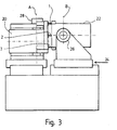
- the grinding spindle assembly is shown at 20 and the work spindle assembly at 22, and the pivoting axis of the grinding spindle is shown at axis A and the orthogonal axis about which the work spindle can pivot is shown at B.
- Probes 1 and 2 can be seen in Figure 1
- probe 3 which is hidden by probe 1 in the plan view in Figure 1 can be seen in Figures 2 and 3.
- the three probes 1, 2 and 3 are respectively mounted at the corners of a triangular bracket 23 secured to the body of the work spindle 22, and they act against anvils (not shown) mounted on a corresponding bracket 25 secured to the body of the grinding spindle 20.
- the probes may alternatively be mounted on the bracket 25, and vice versa the anvils are mounted on the bracket 23.
- the probes lie outside the rotation zone of both the work wheel and the cup grinding wheel (not shown). They may be of any type capable of measuring distance and providing an electric signal output, eg linear displacement probe, capacitive gauge, inductive gauge, air gauge, Linear Variable Differential Transformer (LVDT), or laser interferometer.
- the probes are linear displacement probes containing glass scale encoders.
- a preferred proprietary probe is the Certo (RTM) range type C60M made by Dr Johannes Heidenhain GmbH of D-83301 Traunreut, Germany.
- the infeed axis is identified in Figure 3 at 24.
- a servo motor for adjusting the work spindle assembly about axis B is denoted by 26 and a servo motor for adjusting the grinding spindle assembly about axis A is shown at 28.
- any of a variety of actuators or prime movers may be utilised in place of servo motors.
- control electronics is not shown in detail, nor is the control for the motors associated with the grinding and work spindles contained within the assemblies 20 and 22.
- Axes A and B are defined by stub-shafts extending from either side of the assemblies 20 and 22 respectively and which are carried in aligned bearings (not shown) fitted into the upper ends of support members 30 and 32 in the case of axis B, and into support numbers 34 and 36 in the case of axis A.
- Linear ball screws providing lever-actuation about pivots, usually stub-shafts on bearings may be used.
- axis A is vertical and axis B is horizontal.
- probes 1 and 3 are mounted vertically above and below the axis of the work spindle and probe 2 is mounted midway between the two probes 1 and 3 but displaced in a horizontal plane containing the axis of the work spindle.
- the servo motors 26 and 28 move their respective assemblies about the axes A and B in order to maintain the signal from each probe at a constant value.
- the movement about axis B is controlled by the difference in the output signals between probe 1 and probe 2
- the movement about the axis A is controlled by the difference in the output signal between probe 2 and that of the average of probes 1 and 3.
- the linear infeed of the cup grinding wheel is controlled by the average of all three probes.
- each probe reading has to be adjusted by a gain modifier.
- either spindle could be the grinding spindle, the other in each case being the work spindle.
- one of the spindles may be fixed, while the other spindle is supported within a double gimbal device so as to be able to be pivoted by respective servo motors about the two orthogonal axes.
- the machine may be arranged to be relatively stiff about one of the orthogonal axes, so that angular errors or inaccuracies only require to be corrected in the other axis. In such cases it may be sufficient for one of the spindles to be pivoted only about such other axis, and for the other spindle to be relatively fixed.
- the servo motor may be replaced, for example by on-axis servo motors, off-axis servo motors through gears, ball screws, hydrostatic screws, air cylinders, hydraulic drives, linear motors, piezo stacks, poisson-pushers or thermal displacement drives.
- the pivot axes may, for example be real, flexured, or generated by means of two linears and a rotary, or by tripod or hexapod legs, or any combination thereof.
- a particular application of the present invention is in the grinding of the faces of silicon wafers.
Landscapes
- Engineering & Computer Science (AREA)
- Mechanical Engineering (AREA)
- Chemical & Material Sciences (AREA)
- Ceramic Engineering (AREA)
- Inorganic Chemistry (AREA)
- Constituent Portions Of Griding Lathes, Driving, Sensing And Control (AREA)
- Grinding Of Cylindrical And Plane Surfaces (AREA)
- Grinding And Polishing Of Tertiary Curved Surfaces And Surfaces With Complex Shapes (AREA)
Claims (20)
- Schleifmaschine mit einer Werkstückspindel (22), einer Schleifscheibenspindel (20), einer ersten Befestigungsvorrichtung zum Befestigen einer der Spindeln für eine Schwenkbewegung um eine erste Achse (A), die rechtwinklig zu der Rotationsachse der einen Spindel verläuft, einem ersten Servomotor (26 oder 28), der so betätigbar ist, dass er die Spindel um die erste Achse positioniert, gekennzeichnet durch Sensoren (1, 2, 3), die in der Lage sind, einen Abstand zu messen, um die Position der einen Spindel relativ zu der anderen Spindel exakt zu bestimmen, indem Steuersignale zur Steuerung des ersten Servomotors erzeugt werden.
- Maschine nach Anspruch 1, mit einer zweiten Befestigungsvorrichtung zum Befestigen einer der Spindeln (20, 22) für eine Schwenkbewegung um eine zweite Achse (B) orthogonal zu der ersten Achse, und einen zweiten Servomotor (28 oder 26), der so betätigbar ist, dass er eine der Spindeln um die zweite Achse positioniert, wobei die Sensoren in gleicher Weise den zweiten Servomotor steuern.
- Maschine nach Anspruch 2, bei der die zweite Befestigungsvorrichtung und der zweite Servomotor auf der anderen Spindel vorgesehen sind.
- Maschine nach einem der vorausgehenden Ansprüche, bei der die Sensoren Verschiebungssensoren sind.
- Maschine nach einem der vorausgehenden Ansprüche, bei der die Sensoren Informationen liefern, die ermöglichen, den Winkel zwischen den beiden Spindeln exakt zu bestimmen.
- Maschine nach einem der vorausgehenden Ansprüche, bei dem die Sensoren an drei diskreten Punkten in bezug auf die Spindeln positioniert sind.
- Maschine nach Anspruch 6, bei der kontinuierliche Messungen an den drei diskreten Punkten vorgenommen werden.
- Maschine nach Anspruch 6, bei der die Messungen an den drei diskreten Punkten auf einer sich wiederholenden Basis durchgeführt werden.
- Maschine nach einem der Ansprüche 1 - 4, bei der Messungen an mehr als drei Positionen vorgenommen werden.
- Maschine, die mit Schwenkspindeln und Servormotoren sowie Sensoren nach einem der Ansprüche 3 - 9 ausgerüstet sind, in Verbindung mit einer Signalverarbeitungs und Berechnungsvorrichtung zum Verarbeiten von Signalen aus den Sensoren, um die Servomotoren zu steuern und damit Fehler während des Schleifens aufgrund einer Fehlausrichtung der Spindeln zu reduzieren.
- Maschine nach einem der vorausgehenden Ansprüche, bei der relative Änderungen in den Messungen verwendet werden, um eine Änderung des Winkels zwischen den beiden Spindeln zu berechnen, wobei Steuersignale zur Einstellung eines oder beider Servomotoren berechnet werden, um die Bewegung zu kompensieren, die detektiert worden ist, und um die Spindelachse neu einzustellen, derart, dass die gewünschte Beziehung zwischen den beiden Spindelachsen aufrecht erhalten wird.
- Maschine nach einem der Ansprüche 2 - 10, bei der eine Winkelbewegung einer der beiden Spindeln um ihre Achse verwendet wird, um die Änderung des linearen Abstandes zwischen den beiden Spindeln herzuleiten, der sich aus der Winkelbewegung ergibt, und bei der Schleifscheibenzustell-Steuersignale eingestellt oder korrigiert werden, um jede festgestellte lineare Bewegung zwischen den beiden Spindeln zu kompensieren, derart, dass dadurch die Zustell-Position zwischen Schleifscheiben-Zustellspindel und Werkstückspindel exakt gesteuert wird.
- Maschine nach einem der Ansprüche 2 - 11, bei der jede Spindelanordnung in Achslagern gelagert ist, die innerhalb einer Abstützung so befestigt sind, dass sie um die entsprechende erste oder zweite Achse schwenkbar sind.
- Maschine nach einem der Ansprüche 2 - 11, bei der jede Spindelanordnung durch Biegegelenke abgestützt ist, die eine der beiden orthogonalen Achsen definieren, um die die Spindeln schwenken.
- Maschine nach einem der Ansprüche 1 - 13, bei der die erste Achse (A) vertikal und die zweite Achse (B) horizontal verläuft.
- Planschleifmaschine, bei der eine Schleifspindel (20) und eine Werkstückspindel (22) von entsprechenden Gehäusen aufgenommen sind, wobei die Werkstück- und die Schleifscheibenspindel-Achsen parallel zueinander verlaufen, dadurch gekennzeichnet, dass drei Sonden (1, 2, 3) zur Bestimmung des Abstandes zwischen den beiden Gehäusen angeordnet sind, wobei jeder Sonde ein Sensor zugeordnet ist, der ein Signal erzeugt, das den Abstand zwischen den beiden Gehäusen an den Positionen der Sonden anzeigt, und ferner gekennzeichnet durch einen Servomotor, der auf die Signale anspricht, die durch die Sensoren zur Positionierung einer Spindel relativ zur anderen Spindel erzeugt werden.
- Maschine nach Anspruch 16, bei der Signale proportional dem Abstand digitalisiert sind und die resultierenden Signale in eine digitale Rechenvorrichtung eingespeist werden, die so programmiert ist, dass sie aus den digitalen Signalen eine relative Winkelbewegung zwischen den beiden Spindeln berechnet, wie dies durch die Signale aus den Sonden angezeigt wird, und um Steuersignale zur Einstellung eines Servomotors zu erzeugen, der dem einen oder beiden Gehäusen zugeordnet ist, die die Spindeln aufnehmen, um eine detektierte Winkelverschiebung zu korrigieren, und ferner eine Programmierung vorgenommen wird, mit der aus den digitalen Informationen von den Sensoren und/oder aus den daraus abgeleiteten Steuersignalen zur Steuerung des Servomotors oder der Servomotore Korrektursignale für die Einstellung der Schleifscheibenvorschub-Steuersignale zur Einstellung der Zustell-Position zwischen der Schleifscheibenspindel und der Werkstückspindel berechnet werden, um jede Verschiebung in der relativen Position der beiden Spindeln zu kompensieren.
- Maschine nach Anspruch 16, bei der die Signale aus den Sensoren Analog-Signale sind und entsprechende Verstärkungsmodifikatoren vorgesehen sind.
- Maschine, die mit Schwenkspindeln und Servomotoren sowie Sensoren nach einem der Ansprüche 3 - 18 ausgerüstet sind, in Verbindung mit Signalverarbeitungs- und -berechnungsvorrichtungen zur Verarbeitung von Signalen aus den Sensoren, um die Servomotoren zu steuern und damit Fehler während des Schleifens aufgrund einer Fehlausrichtung der Spindeln zu reduzieren.
- Maschine nach Anspruch 9, bei der verarbeitete und berechnete Signale die Vorschub-Steuersignale zusätzlich zu den Winkelpositionen der Spindeln berechnen.
Applications Claiming Priority (3)
| Application Number | Priority Date | Filing Date | Title |
|---|---|---|---|
| GB9725203 | 1997-11-29 | ||
| GBGB9725203.5A GB9725203D0 (en) | 1997-11-29 | 1997-11-29 | Improvements in and relating to grinding machines |
| PCT/GB1998/003265 WO1999028081A1 (en) | 1997-11-29 | 1998-11-02 | Improved grinding machine |
Publications (2)
| Publication Number | Publication Date |
|---|---|
| EP1034064A1 EP1034064A1 (de) | 2000-09-13 |
| EP1034064B1 true EP1034064B1 (de) | 2002-01-16 |
Family
ID=10822798
Family Applications (1)
| Application Number | Title | Priority Date | Filing Date |
|---|---|---|---|
| EP98951580A Expired - Lifetime EP1034064B1 (de) | 1997-11-29 | 1998-11-02 | Verbesserte schleifmaschine |
Country Status (8)
| Country | Link |
|---|---|
| US (1) | US6443818B1 (de) |
| EP (1) | EP1034064B1 (de) |
| KR (1) | KR20010015847A (de) |
| CN (1) | CN1105621C (de) |
| DE (1) | DE69803223D1 (de) |
| ES (1) | ES2169928T3 (de) |
| GB (2) | GB9725203D0 (de) |
| WO (1) | WO1999028081A1 (de) |
Families Citing this family (10)
| Publication number | Priority date | Publication date | Assignee | Title |
|---|---|---|---|---|
| US6132295A (en) * | 1999-08-12 | 2000-10-17 | Applied Materials, Inc. | Apparatus and method for grinding a semiconductor wafer surface |
| DE10135139C1 (de) * | 2001-07-19 | 2002-11-21 | Thielenhaus Ernst Gmbh & Co Kg | Vorrichtung zur Finishbearbeitung von Werkstücken |
| US7011567B2 (en) * | 2004-02-05 | 2006-03-14 | Robert Gerber | Semiconductor wafer grinder |
| US7163441B2 (en) * | 2004-02-05 | 2007-01-16 | Robert Gerber | Semiconductor wafer grinder |
| DE102007024760A1 (de) * | 2007-05-26 | 2008-07-17 | Thielenhaus Technologies Gmbh | Verfahren zum Feinstschleifen von im Querschnitt gekrümmten Flächen an ringförmigen Werkstücken |
| US7645180B2 (en) * | 2007-10-18 | 2010-01-12 | Thielenhaus Microfinish Corporation | Method for finishing a workpiece |
| CN102120311B (zh) * | 2010-12-31 | 2012-12-05 | 东华大学 | 一种支持天线罩内外型线检测与修磨的多功能复合装备 |
| JP5841846B2 (ja) * | 2012-01-11 | 2016-01-13 | 株式会社ディスコ | 研削装置 |
| CN103056772A (zh) * | 2012-12-25 | 2013-04-24 | 北京工业大学 | 一种基于负柔度原理的磨床刚度补偿方法 |
| CN105014486A (zh) * | 2015-08-06 | 2015-11-04 | 山东云峰数控科技有限公司 | 雕刻刀专用四轴数控打磨设备 |
Family Cites Families (6)
| Publication number | Priority date | Publication date | Assignee | Title |
|---|---|---|---|---|
| SE343502B (de) * | 1969-06-18 | 1972-03-13 | Uva Ab | |
| DE3436226A1 (de) * | 1984-10-03 | 1986-04-03 | Maschinenfabrik Gehring Gmbh & Co Kg, 7302 Ostfildern | Schleifmaschine |
| US4858387A (en) * | 1986-10-30 | 1989-08-22 | Clough Arthur H | Apparatus for grinding a workpiece |
| JPS63191559A (ja) * | 1987-02-04 | 1988-08-09 | Mazda Motor Corp | 研削盤のスイベル装置 |
| DE3807490A1 (de) * | 1988-03-08 | 1989-09-21 | Studer Ag Fritz | Universalschleifmaschine |
| JPH06134654A (ja) * | 1992-10-26 | 1994-05-17 | Matsushita Electric Ind Co Ltd | 回転・切り込み装置 |
-
1997
- 1997-11-29 GB GBGB9725203.5A patent/GB9725203D0/en not_active Ceased
-
1998
- 1998-11-02 EP EP98951580A patent/EP1034064B1/de not_active Expired - Lifetime
- 1998-11-02 ES ES98951580T patent/ES2169928T3/es not_active Expired - Lifetime
- 1998-11-02 CN CN98811603A patent/CN1105621C/zh not_active Expired - Fee Related
- 1998-11-02 GB GB9823788A patent/GB2331720B/en not_active Expired - Fee Related
- 1998-11-02 KR KR1020007005853A patent/KR20010015847A/ko not_active Abandoned
- 1998-11-02 DE DE69803223T patent/DE69803223D1/de not_active Expired - Fee Related
- 1998-11-02 WO PCT/GB1998/003265 patent/WO1999028081A1/en not_active Ceased
- 1998-11-12 US US09/554,416 patent/US6443818B1/en not_active Expired - Fee Related
Also Published As
| Publication number | Publication date |
|---|---|
| ES2169928T3 (es) | 2002-07-16 |
| KR20010015847A (ko) | 2001-02-26 |
| GB2331720A (en) | 1999-06-02 |
| DE69803223D1 (de) | 2002-02-21 |
| EP1034064A1 (de) | 2000-09-13 |
| CN1280530A (zh) | 2001-01-17 |
| GB2331720B (en) | 2000-11-01 |
| GB9823788D0 (en) | 1998-12-23 |
| WO1999028081A1 (en) | 1999-06-10 |
| US6443818B1 (en) | 2002-09-03 |
| GB9725203D0 (en) | 1998-01-28 |
| CN1105621C (zh) | 2003-04-16 |
Similar Documents
| Publication | Publication Date | Title |
|---|---|---|
| US8006398B2 (en) | Method for scanning the surface of a workpiece | |
| US6971183B2 (en) | Probe head for coordinate measuring machines | |
| US4961267A (en) | Method and apparatus for making coordinate measurements | |
| EP0527739B1 (de) | Servo-geführte trägertischeinrichtung | |
| US5669150A (en) | Coordinate measuring machine having articulated arm | |
| US8786243B2 (en) | Method and device for preparing error map and numerically controlled machine tool having error map preparation function | |
| US7535193B2 (en) | Five axis compensated rotating stage | |
| US6412329B1 (en) | Method of and apparatus for reducing vibrations on probes carried by coordinate measuring machines | |
| EP1034064B1 (de) | Verbesserte schleifmaschine | |
| WO2006109094A1 (en) | Method of error correction | |
| JPS6389253A (ja) | 機械上の点の温度に依存した変位の補償装置 | |
| US5727326A (en) | Pivotable two-coordinate scanning head with horizontal main axis | |
| US4504048A (en) | Micro-adjustable displacement and rotation setting apparatus | |
| GB2207371A (en) | Apparatus and methods for automatically determining the radius described by a tool tip mounted for a rotary machining operation | |
| JP4992078B2 (ja) | 傾斜角測定装置、これを搭載した工作機械および工作機械の傾斜角校正方法 | |
| US5616917A (en) | Device for measuring an angle between pivotally-connected members | |
| GB2334690A (en) | Improved grinding machine. | |
| US20070152391A1 (en) | Error corrected positioning stage | |
| JP2005081444A (ja) | 駆動装置の精度測定装置、駆動装置の精度測定方法、駆動装置の精度測定プログラム、このプログラムを記録した記録媒体、および、駆動装置の校正方法 | |
| JP2868126B2 (ja) | 静圧ガイドの真直度補正機構 | |
| JPH0639042B2 (ja) | テ−ブルの駆動装置 | |
| JPS6020841A (ja) | 工作機械等における移動体の位置誤差補正装置 | |
| GB2039085A (en) | Drive assembly for a pivotally mounted part, such as a machine tool head | |
| JPH0592362A (ja) | 研磨ヘツドおよび研磨装置 | |
| JPH0679254B2 (ja) | 多軸位置決め装置 |
Legal Events
| Date | Code | Title | Description |
|---|---|---|---|
| PUAI | Public reference made under article 153(3) epc to a published international application that has entered the european phase |
Free format text: ORIGINAL CODE: 0009012 |
|
| 17P | Request for examination filed |
Effective date: 20000517 |
|
| AK | Designated contracting states |
Kind code of ref document: A1 Designated state(s): CH DE ES FR GB IT LI |
|
| GRAG | Despatch of communication of intention to grant |
Free format text: ORIGINAL CODE: EPIDOS AGRA |
|
| GRAG | Despatch of communication of intention to grant |
Free format text: ORIGINAL CODE: EPIDOS AGRA |
|
| GRAH | Despatch of communication of intention to grant a patent |
Free format text: ORIGINAL CODE: EPIDOS IGRA |
|
| 17Q | First examination report despatched |
Effective date: 20010504 |
|
| GRAH | Despatch of communication of intention to grant a patent |
Free format text: ORIGINAL CODE: EPIDOS IGRA |
|
| GRAA | (expected) grant |
Free format text: ORIGINAL CODE: 0009210 |
|
| REG | Reference to a national code |
Ref country code: GB Ref legal event code: IF02 |
|
| AK | Designated contracting states |
Kind code of ref document: B1 Designated state(s): CH DE ES FR GB IT LI |
|
| REG | Reference to a national code |
Ref country code: CH Ref legal event code: EP |
|
| REG | Reference to a national code |
Ref country code: CH Ref legal event code: NV Representative=s name: FREI PATENTANWALTSBUERO |
|
| REF | Corresponds to: |
Ref document number: 69803223 Country of ref document: DE Date of ref document: 20020221 |
|
| REG | Reference to a national code |
Ref country code: ES Ref legal event code: FG2A Ref document number: 2169928 Country of ref document: ES Kind code of ref document: T3 |
|
| ET | Fr: translation filed | ||
| PLBE | No opposition filed within time limit |
Free format text: ORIGINAL CODE: 0009261 |
|
| STAA | Information on the status of an ep patent application or granted ep patent |
Free format text: STATUS: NO OPPOSITION FILED WITHIN TIME LIMIT |
|
| 26N | No opposition filed | ||
| PGFP | Annual fee paid to national office [announced via postgrant information from national office to epo] |
Ref country code: FR Payment date: 20041119 Year of fee payment: 7 |
|
| PGFP | Annual fee paid to national office [announced via postgrant information from national office to epo] |
Ref country code: CH Payment date: 20041125 Year of fee payment: 7 |
|
| PGFP | Annual fee paid to national office [announced via postgrant information from national office to epo] |
Ref country code: ES Payment date: 20041209 Year of fee payment: 7 |
|
| PGFP | Annual fee paid to national office [announced via postgrant information from national office to epo] |
Ref country code: DE Payment date: 20041230 Year of fee payment: 7 |
|
| PG25 | Lapsed in a contracting state [announced via postgrant information from national office to epo] |
Ref country code: IT Free format text: LAPSE BECAUSE OF NON-PAYMENT OF DUE FEES;WARNING: LAPSES OF ITALIAN PATENTS WITH EFFECTIVE DATE BEFORE 2007 MAY HAVE OCCURRED AT ANY TIME BEFORE 2007. THE CORRECT EFFECTIVE DATE MAY BE DIFFERENT FROM THE ONE RECORDED. Effective date: 20051102 |
|
| PG25 | Lapsed in a contracting state [announced via postgrant information from national office to epo] |
Ref country code: ES Free format text: LAPSE BECAUSE OF NON-PAYMENT OF DUE FEES Effective date: 20051103 |
|
| PG25 | Lapsed in a contracting state [announced via postgrant information from national office to epo] |
Ref country code: LI Free format text: LAPSE BECAUSE OF NON-PAYMENT OF DUE FEES Effective date: 20051130 Ref country code: CH Free format text: LAPSE BECAUSE OF NON-PAYMENT OF DUE FEES Effective date: 20051130 |
|
| REG | Reference to a national code |
Ref country code: GB Ref legal event code: 732E |
|
| PG25 | Lapsed in a contracting state [announced via postgrant information from national office to epo] |
Ref country code: DE Free format text: LAPSE BECAUSE OF NON-PAYMENT OF DUE FEES Effective date: 20060601 |
|
| REG | Reference to a national code |
Ref country code: CH Ref legal event code: PUE Owner name: CINETIC LANDIS GRINDING LIMITED Free format text: UNOVA U.K. LIMITED#26, TEMPLE STREET#AYLESBURY, BUCKINGHAMSHIRE HP20 2RQ (GB) -TRANSFER TO- CINETIC LANDIS GRINDING LIMITED#CROSS HILLS#KEIGHLEY, WEST YORKSHIRE BD20 7SD (GB) Ref country code: CH Ref legal event code: NV Representative=s name: FREI PATENTANWALTSBUERO |
|
| REG | Reference to a national code |
Ref country code: CH Ref legal event code: PL |
|
| PG25 | Lapsed in a contracting state [announced via postgrant information from national office to epo] |
Ref country code: FR Free format text: LAPSE BECAUSE OF NON-PAYMENT OF DUE FEES Effective date: 20060731 |
|
| REG | Reference to a national code |
Ref country code: FR Ref legal event code: TP |
|
| REG | Reference to a national code |
Ref country code: FR Ref legal event code: ST Effective date: 20060731 |
|
| REG | Reference to a national code |
Ref country code: ES Ref legal event code: FD2A Effective date: 20051103 |
|
| PGFP | Annual fee paid to national office [announced via postgrant information from national office to epo] |
Ref country code: GB Payment date: 20110906 Year of fee payment: 14 |
|
| GBPC | Gb: european patent ceased through non-payment of renewal fee |
Effective date: 20121102 |
|
| PG25 | Lapsed in a contracting state [announced via postgrant information from national office to epo] |
Ref country code: GB Free format text: LAPSE BECAUSE OF NON-PAYMENT OF DUE FEES Effective date: 20121102 |