EP1035547A1 - Eckteilverstärkngsvorrichtung für gestell einer plattenvorrichtung - Google Patents
Eckteilverstärkngsvorrichtung für gestell einer plattenvorrichtung Download PDFInfo
- Publication number
- EP1035547A1 EP1035547A1 EP98944307A EP98944307A EP1035547A1 EP 1035547 A1 EP1035547 A1 EP 1035547A1 EP 98944307 A EP98944307 A EP 98944307A EP 98944307 A EP98944307 A EP 98944307A EP 1035547 A1 EP1035547 A1 EP 1035547A1
- Authority
- EP
- European Patent Office
- Prior art keywords
- chassis
- section
- reinforcing
- reinforcing base
- damper
- Prior art date
- Legal status (The legal status is an assumption and is not a legal conclusion. Google has not performed a legal analysis and makes no representation as to the accuracy of the status listed.)
- Granted
Links
Images






Classifications
-
- G—PHYSICS
- G11—INFORMATION STORAGE
- G11B—INFORMATION STORAGE BASED ON RELATIVE MOVEMENT BETWEEN RECORD CARRIER AND TRANSDUCER
- G11B33/00—Constructional parts, details or accessories not provided for in the other groups of this subclass
- G11B33/12—Disposition of constructional parts in the apparatus, e.g. of power supply, of modules
- G11B33/121—Disposition of constructional parts in the apparatus, e.g. of power supply, of modules the apparatus comprising a single recording/reproducing device
-
- G—PHYSICS
- G11—INFORMATION STORAGE
- G11B—INFORMATION STORAGE BASED ON RELATIVE MOVEMENT BETWEEN RECORD CARRIER AND TRANSDUCER
- G11B33/00—Constructional parts, details or accessories not provided for in the other groups of this subclass
- G11B33/02—Cabinets; Cases; Stands; Disposition of apparatus therein or thereon
- G11B33/08—Insulation or absorption of undesired vibrations or sounds
Definitions
- the present invention relates to a corner section reinforcing device for a chassis used for a disk device which reinforces a bent corner section of a chassis used for a disk device and which protects a disk playing unit from exterior vibrations.
- a disk device which plays an optical disk stores a disk playing unit which mounts a turntable or a pick up so as to be freely movable in the chassis due to a damping member such as a coil spring. This enables protection from any influence on the disk playing unit due to vibration or shocks from the outside coming into contact with the chassis.
- a disk device for use in an automobile comprises a damping member due to the fact that it is liable to be in contact with continuous vibrations.
- the chassis is provided with a lateral plate which is formed by bending a metal plate and a corner section which is formed by two independent adjacent lateral plates.
- a lateral plate which is formed by bending a metal plate
- a corner section which is formed by two independent adjacent lateral plates.
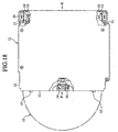
- Figure 18 is a plan view of a chassis of a conventional disk device.
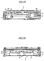
- Figure 19 is a lateral view of the chassis in Figure 8 seen from direction E.
- Figure 20 is a lateral view of the chassis in Figure 8 seen from direction F.
- reference numeral 11 denotes a chassis
- 12 is an upright lateral plate which is bent in order to form a lateral face of the chassis 11
- 13 is an optical disk
- 14 is a disk playing unit which plays optical disks, and which is stored in the chassis so as to freely movable due to a coil spring and a damper.
- 14a is an engagement pin provided in the disk playing unit 14.
- 15 is a caulked section to secure the lateral plates 12, 12 to each other which reinforce the corner section of the chassis 11.
- 16 is a damper which is filled with a viscous liquid and which is disclosed for example in JP-A-7-272470.
- 17 is a bolt which secures the damper 16 to the lateral plate 12.
- the corner section of the chassis 11 is reinforced by the caulking section 15.
- the disk playing unit 14 displaces relative to the chassis 11 in response to external vibrations coming into contact with the chassis 11.
- the damper 16 in this sense applies a braking operation on the engaging pin 14a and absorbs external vibration due to the viscosity of the stored viscous liquid and its elastic deformation. Thus the external vibrations are absorbed.
- the present invention is proposed to solve the above problems and has the object of providing a corner section reinforcing device for a chassis used for a disk device which can easily reinforce the corner section of a chassis which is produced by progressive die molding and which is produced at a low cost.
- the present invention is provided with a reinforcing base section which is fixed to and engages with two independent lateral plates formed on the corner section of a chassis and which reinforces a corner section, and a damping section which is provided on said reinforcing base section and which absorbs the vibrations of a disk playing unit.
- the corner section of a chassis which is produced by progressive die molding, is simply reinforced by a reinforcing base section.
- a damping section is simultaneously disposed by fixing the reinforcing base section to the chassis, it is possible to greatly reduce the number of components and improve the efficiency of the assembly procedure at all stages as well as reduce costs.
- the present invention is provided with an engagement hole into which is inserted an engaging piece which is formed on a lateral plate of the chassis.
- the engaging hole of the reinforcing base section of the present invention is provided with a projection which engages with the engaging hole which is formed on the engaging piece of the independent lateral plates.
- the reinforcing base section and the damper section of the present invention are formed by double layer molding.
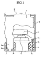
- Figure 1 is a partial cross section showing the engaging position of the chassis and the reinforcing section of the corner section reinforcing device for a chassis used for a disk device according to a first embodiment of the present invention.
- Figure 2 is a partial cross section showing the engaging position of the damper section and the disk playing unit.
- Figure 3 is a front perspective view of the corner section reinforcing device of a chassis used for a disk device.
- Figure 4 is a rear perspective view of the corner section reinforcing device of a chassis used for a disk device.
- Figure 5 is a plan view of a corner section reinforcing device of a chassis used for a disk device.
- Figure 6 is a partial cross section of a reinforcing base section.
- Figure 7 is a partial cross section of a damper section.
- Figure 8 is a plan view of a chassis of a disk device.
- Figure 9 is a lateral view of a chassis in Figure 8 as seen from direction A.
- Figure 10 is a lateral view of the chassis in Figure 8 as seen from direction B.
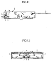
- Figure 11 is a lateral view of the chassis in Figure 8 as seen from direction C.
- Figure 12 is a lateral view of the chassis in Figure 8 as seen from direction D.
- reference numeral 1 refers to a chassis which is manufactured by progressive die molding
- 2 are independent lateral plates which are formed by bending in order to form a lateral face of the chassis 1
- 2a is an engaging piece which is formed on the independent lateral plates
- 2b is a step which is formed on the tip of the engaging piece 2a
- 3 is an optical disk
- 4 is a disk playing unit which mounts a turn table or a pickup or the like (not shown) in order to play the optical disk and which is stored so as to be freely displaceable in the chassis due to a coil spring (not shown).
- 4a is an engaging pin provided on the disk playing unit.
- 5 is a reinforcing base section which is fixed to and engages with the engaging piece 2a of the independent lateral plate 2 and which reinforces the corner section formed by the lateral plates 2, 2.
- the reinforcing base section 5 may be formed by hard resin.
- 5a is an engaging hole which is formed so that an engaging piece 2a may be inserted therein.
- 5b is a step which engages with the step 2b of the engaging piece 2a.
- the damper section 6 is a damper section which absorbs the vibrations of the disk playing unit and which may be integrated with the above mentioned reinforcing base section 5 by being formed by double layer molding.
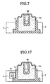
- the damper section 6, as shown in Figures 2 and 7, is formed in a closed tubular shape by a flexible material such as a butyl-type rubber.
- a viscous fluid 6a such as silicon oil fills the interior.
- 6b is an engaging indentation which engages with the engaging pin of the disk playing unit 4.
- a corner section reinforcing device for a chassis used for a disk device as formed from a reinforcing base section 5 and a damper section 6 and is disposed adjacent to the center of the chassis 1 with corner sections at two positions which are formed by independent lateral plates 2, 2 as shown in Figure 8.
- each independent lateral plate 2 engages with the engaging hole 5a of the reinforcing base section 5
- both independent lateral plates 2 are connected by the reinforcing base section 5.
- the relative movement of the independent lateral plates 2 is limited by the reinforcing base section 5.
- a step 2b is provided on the engaging piece 2a and a step 5b is provided on the engaging hole 5a, it is possible to limit movement during insertion and determine the position of the reinforcing base section 5 easily.
- the position of the damper 6 is simultaneously determined by the disposition of the reinforcing base section 5 to the position above. Since a screw member to secure the damper section is unnecessary in contradistinction to the conventional example, it is possible to reduce the number of components and greatly reduce required time and labor.
- the disk playing unit 4 receives external vibrations which come into contact with the chassis 1 and displaces relative to the chassis 1. At such times, the damper 6 applies a braking force to the engaging pin 4a due to the viscosity of the viscous liquid 6a and its elastic deformation and thus absorbs external vibrations. Therefore the damper 6 returns to its original position due to an elastic return force after the braking operation.
- the reinforcement of a corner section of a chassis which is formed by progressive die molding is simply enabled by a reinforcing base section 5.
- a damper 6 may be simultaneously disposed by the fixation of the reinforcing base section 5 to the chassis 1.
- the reinforcing base section 5 and the damper section 6 are formed by double layer molding, it is possible to simply integrate the two although they are formed from different materials, to mass produce the device and to reduce manufacturing costs.
- the invention was explained as applied to a disk device.
- the invention is however not limited in this respect and may obtain the same effect by being applied to various devices which require protection from vibration and reinforcement of a corner section of a chassis.
- Figure 13 is a partial cross section of a reinforcing base section engaging with a chassis of a corner section reinforcing device for a chassis used for a disk device according to a second embodiment of the present invention.
- Figure 14 is a partial cross section of the engaging position of a damper section and a disk playing unit.
- Figure 15 is a front perspective view of a corner section reinforcing device for a chassis used for a disk device.
- Figure 16 is a partial cross section of a reinforcing base section.
- Figure 17 is a partial cross section of a damper section.
- 2c is an engaging hole which is provided in the engaging piece 2a.
- 5c is a projection which is provided in the engaging hole 5a so as to engage with the engaging hole 2c.
- the present invention according to embodiment 2 apart from obtaining the same effect as embodiment 1 also prevents the detachment of the reinforcing base section 5 from the engaging piece 2a.
- a corner section reinforcing device for a chassis used for a disk device according to the present invention may be applied to a disk device in order to simply and cheaply reinforce the corner section of a chassis which is formed by progressive die molding.
Landscapes
- Vibration Prevention Devices (AREA)
- Holding Or Fastening Of Disk On Rotational Shaft (AREA)
Applications Claiming Priority (1)
| Application Number | Priority Date | Filing Date | Title |
|---|---|---|---|
| PCT/JP1998/004383 WO2000019433A1 (en) | 1998-09-29 | 1998-09-29 | Corner part reinforcing device of disc device chassis |
Publications (3)
| Publication Number | Publication Date |
|---|---|
| EP1035547A1 true EP1035547A1 (de) | 2000-09-13 |
| EP1035547A4 EP1035547A4 (de) | 2003-01-22 |
| EP1035547B1 EP1035547B1 (de) | 2004-11-24 |
Family
ID=14209095
Family Applications (1)
| Application Number | Title | Priority Date | Filing Date |
|---|---|---|---|
| EP98944307A Expired - Lifetime EP1035547B1 (de) | 1998-09-29 | 1998-09-29 | Eckteilverstärkngsvorrichtung für gestell einer plattenvorrichtung |
Country Status (6)
| Country | Link |
|---|---|
| US (1) | US6392982B1 (de) |
| EP (1) | EP1035547B1 (de) |
| JP (1) | JP3621349B2 (de) |
| AU (1) | AU9187998A (de) |
| DE (1) | DE69827841T2 (de) |
| WO (1) | WO2000019433A1 (de) |
Families Citing this family (14)
| Publication number | Priority date | Publication date | Assignee | Title |
|---|---|---|---|---|
| CN1057302C (zh) * | 1997-08-27 | 2000-10-11 | 中国科学院上海生物化学研究所 | 抑制乙型肝炎病毒复制的反义脱氧寡核苷酸 |
| DE19838753A1 (de) * | 1998-08-26 | 2000-03-02 | Philips Corp Intellectual Pty | Flüssigkeitsgefüllter Dämpfer für ein erschütterungsempfindliches Gerät und Verfahren zu dessen Herstellung |
| JP4240923B2 (ja) * | 2001-12-14 | 2009-03-18 | ポリマテック株式会社 | ダンパーおよびメカシャーシの防振構造 |
| US20050259352A1 (en) * | 2004-05-19 | 2005-11-24 | Leclair Stephen P | Bumper device for data storage apparatus |
| US7218474B2 (en) * | 2004-06-10 | 2007-05-15 | Seagate Technology, Llc | Assembly rail corners shaped to reduce shock |
| JP2006190375A (ja) * | 2005-01-05 | 2006-07-20 | Hitachi Global Storage Technologies Netherlands Bv | 磁気ディスク装置 |
| JP4908798B2 (ja) * | 2005-08-05 | 2012-04-04 | ポリマテック株式会社 | 粘性流体封入ダンパー |
| US7420774B2 (en) * | 2005-09-29 | 2008-09-02 | Seagate Technology Llc | Housing with a rail shaped to reduce impact damage |
| DE102006036343B4 (de) * | 2006-08-03 | 2012-06-06 | Trelleborg Automotive Germany Gmbh | Dämpfendes Aggregatlager |
| US8882680B2 (en) | 2011-12-02 | 2014-11-11 | Interscope, Inc. | Insertable endoscopic instrument for tissue removal |
| US9808146B2 (en) | 2011-12-02 | 2017-11-07 | Interscope, Inc. | Endoscopic tool for debriding and removing polyps |
| US9204868B2 (en) | 2011-12-02 | 2015-12-08 | Interscope, Inc. | Methods and apparatus for removing material from within a mammalian cavity using an insertable endoscopic instrument |
| US11392720B2 (en) | 2016-06-10 | 2022-07-19 | OneTrust, LLC | Data processing systems for verification of consent and notice processing and related methods |
| US11169572B2 (en) * | 2019-08-07 | 2021-11-09 | Hand Held Products, Inc. | Protective housing for a mobile device |
Family Cites Families (16)
| Publication number | Priority date | Publication date | Assignee | Title |
|---|---|---|---|---|
| US4713714A (en) * | 1985-11-26 | 1987-12-15 | Motorola Computer Systems, Inc. | Computer peripheral shock mount for limiting motion-induced errors |
| JPS62200588A (ja) * | 1986-02-26 | 1987-09-04 | Pioneer Electronic Corp | 音響機器等の防振構造 |
| JPH02130783A (ja) * | 1988-11-11 | 1990-05-18 | Nippon I B M Kk | 防振構造および磁気ディスク装置 |
| US4980786A (en) * | 1988-11-14 | 1990-12-25 | Maxtor Corporation | Method and apparatus for improved thermal isolation and stability of disk drives |
| GB2241042B (en) * | 1990-02-16 | 1994-01-05 | Pioneer Electronic Corp | Damper filled with oil |
| JP2529329Y2 (ja) | 1990-06-29 | 1997-03-19 | オリンパス光学工業株式会社 | 情報読取装置の制振装置 |
| CA2089792A1 (en) * | 1992-04-30 | 1993-10-31 | Jeffrey F. Boigenzahn | Optimum rotational mode decoupling shock mount configuration for dasds |
| JPH07254259A (ja) * | 1994-03-15 | 1995-10-03 | Hitachi Ltd | 磁気ディスク装置 |
| JP2991924B2 (ja) | 1994-03-29 | 1999-12-20 | タナシン電機株式会社 | ディスク再生装置の再生ユニット支持装置 |
| KR950030643A (ko) * | 1994-04-27 | 1995-11-24 | 김광호 | 화면크기 전환장치 |
| US6108163A (en) * | 1994-10-12 | 2000-08-22 | International Business Machines Corporation | Sensitive sensor internally mounted shock for a disk drive |
| KR100224820B1 (ko) * | 1995-12-15 | 1999-10-15 | 윤종용 | 진동을 흡수하는 댐퍼와 이 댐퍼를 사용하는 광디스크드라이브 |
| JP3195213B2 (ja) * | 1995-12-18 | 2001-08-06 | 株式会社日立製作所 | 回転形情報記録再生装置 |
| JPH10112176A (ja) * | 1996-10-04 | 1998-04-28 | Sony Corp | 記録再生装置 |
| US6034841A (en) * | 1998-05-29 | 2000-03-07 | International Business Machines Corporation | Disk drive with composite sheet metal and encapsulated plastic base |
| JP2000163944A (ja) * | 1998-11-27 | 2000-06-16 | Hitachi Ltd | 磁気ディスク装置 |
-
1998
- 1998-09-29 JP JP2000572848A patent/JP3621349B2/ja not_active Expired - Lifetime
- 1998-09-29 EP EP98944307A patent/EP1035547B1/de not_active Expired - Lifetime
- 1998-09-29 AU AU91879/98A patent/AU9187998A/en not_active Abandoned
- 1998-09-29 US US09/554,497 patent/US6392982B1/en not_active Expired - Lifetime
- 1998-09-29 WO PCT/JP1998/004383 patent/WO2000019433A1/ja not_active Ceased
- 1998-09-29 DE DE69827841T patent/DE69827841T2/de not_active Expired - Lifetime
Also Published As
| Publication number | Publication date |
|---|---|
| EP1035547B1 (de) | 2004-11-24 |
| JP3621349B2 (ja) | 2005-02-16 |
| AU9187998A (en) | 2000-04-17 |
| DE69827841D1 (de) | 2004-12-30 |
| DE69827841T2 (de) | 2005-11-03 |
| US6392982B1 (en) | 2002-05-21 |
| WO2000019433A1 (en) | 2000-04-06 |
| EP1035547A4 (de) | 2003-01-22 |
Similar Documents
| Publication | Publication Date | Title |
|---|---|---|
| US6392982B1 (en) | Corner part reinforcing device of disc device chassis | |
| KR100669287B1 (ko) | 차량용 하드디스크 드라이브 방진 장치 및 그 조립방법 | |
| US5595430A (en) | Resilient retainer for vibration sensitive components | |
| CN101877224B (zh) | 盘驱动器悬架及其制造方法 | |
| JPWO2000019433A1 (ja) | ディスク装置用シャーシの角部補強装置 | |
| KR0138079B1 (ko) | 광디스크플레이어의 방진.방충장치 | |
| JP4518509B2 (ja) | 特に自動車のためのワイパ装置 | |
| US20060139873A1 (en) | Electronic instrument having recording and reproduction device | |
| JP6702631B2 (ja) | 電子装置 | |
| US6439553B1 (en) | Vibration-preventive support device | |
| JP2899777B2 (ja) | 防振支持装置 | |
| KR20000017453A (ko) | 충격에 민감한 장치를 위한 액체 충전된 댐퍼와, 상기한 댐퍼를 제조하는 방법 | |
| JP2004197832A (ja) | 緩衝装置及び防振装置 | |
| JPH068353Y2 (ja) | 防振支持装置 | |
| JP2991924B2 (ja) | ディスク再生装置の再生ユニット支持装置 | |
| JP3521554B2 (ja) | ダイナミックダンパ | |
| JPS62288739A (ja) | ダンパ−装置及びその製造方法 | |
| JP2944320B2 (ja) | 車載用機器の防振装置 | |
| JP3676640B2 (ja) | 車載機器のダンパー取付構造 | |
| KR100654627B1 (ko) | 하드디스크 드라이브의 충격흡수장치 | |
| JPH0232901Y2 (de) | ||
| JP3201067B2 (ja) | 車載用電子機器の防振装置 | |
| KR100278693B1 (ko) | 디스크 재생장치의 재생 유닛 지지장치 | |
| JP3545072B2 (ja) | 電子機器用ダンパー装置 | |
| JP2003139182A (ja) | 粘性流体封入ダンパ及びその製造方法 |
Legal Events
| Date | Code | Title | Description |
|---|---|---|---|
| PUAI | Public reference made under article 153(3) epc to a published international application that has entered the european phase |
Free format text: ORIGINAL CODE: 0009012 |
|
| 17P | Request for examination filed |
Effective date: 20000526 |
|
| AK | Designated contracting states |
Kind code of ref document: A1 Designated state(s): DE FR GB NL SE |
|
| A4 | Supplementary search report drawn up and despatched |
Effective date: 20021210 |
|
| AK | Designated contracting states |
Kind code of ref document: A4 Designated state(s): DE FR GB NL SE |
|
| 17Q | First examination report despatched |
Effective date: 20030310 |
|
| GRAP | Despatch of communication of intention to grant a patent |
Free format text: ORIGINAL CODE: EPIDOSNIGR1 |
|
| GRAS | Grant fee paid |
Free format text: ORIGINAL CODE: EPIDOSNIGR3 |
|
| GRAA | (expected) grant |
Free format text: ORIGINAL CODE: 0009210 |
|
| AK | Designated contracting states |
Kind code of ref document: B1 Designated state(s): DE FR GB NL SE |
|
| PG25 | Lapsed in a contracting state [announced via postgrant information from national office to epo] |
Ref country code: NL Free format text: LAPSE BECAUSE OF FAILURE TO SUBMIT A TRANSLATION OF THE DESCRIPTION OR TO PAY THE FEE WITHIN THE PRESCRIBED TIME-LIMIT Effective date: 20041124 Ref country code: FR Free format text: LAPSE BECAUSE OF FAILURE TO SUBMIT A TRANSLATION OF THE DESCRIPTION OR TO PAY THE FEE WITHIN THE PRESCRIBED TIME-LIMIT Effective date: 20041124 |
|
| REG | Reference to a national code |
Ref country code: GB Ref legal event code: FG4D |
|
| REF | Corresponds to: |
Ref document number: 69827841 Country of ref document: DE Date of ref document: 20041230 Kind code of ref document: P |
|
| PG25 | Lapsed in a contracting state [announced via postgrant information from national office to epo] |
Ref country code: SE Free format text: LAPSE BECAUSE OF FAILURE TO SUBMIT A TRANSLATION OF THE DESCRIPTION OR TO PAY THE FEE WITHIN THE PRESCRIBED TIME-LIMIT Effective date: 20050224 |
|
| NLV1 | Nl: lapsed or annulled due to failure to fulfill the requirements of art. 29p and 29m of the patents act | ||
| PG25 | Lapsed in a contracting state [announced via postgrant information from national office to epo] |
Ref country code: GB Free format text: LAPSE BECAUSE OF NON-PAYMENT OF DUE FEES Effective date: 20050929 |
|
| PLBE | No opposition filed within time limit |
Free format text: ORIGINAL CODE: 0009261 |
|
| STAA | Information on the status of an ep patent application or granted ep patent |
Free format text: STATUS: NO OPPOSITION FILED WITHIN TIME LIMIT |
|
| 26N | No opposition filed |
Effective date: 20050825 |
|
| EN | Fr: translation not filed | ||
| GBPC | Gb: european patent ceased through non-payment of renewal fee |
Effective date: 20050929 |
|
| REG | Reference to a national code |
Ref country code: DE Ref legal event code: R084 Ref document number: 69827841 Country of ref document: DE Effective date: 20110506 Ref country code: DE Ref legal event code: R084 Ref document number: 69827841 Country of ref document: DE Effective date: 20110630 |
|
| PGFP | Annual fee paid to national office [announced via postgrant information from national office to epo] |
Ref country code: DE Payment date: 20170927 Year of fee payment: 20 |
|
| REG | Reference to a national code |
Ref country code: DE Ref legal event code: R071 Ref document number: 69827841 Country of ref document: DE |