EP1036869A1 - Verfahren und Vorrichtung zur Überwachung von Schussfaden in Webverfahren oder dergleichen - Google Patents
Verfahren und Vorrichtung zur Überwachung von Schussfaden in Webverfahren oder dergleichen Download PDFInfo
- Publication number
- EP1036869A1 EP1036869A1 EP00104465A EP00104465A EP1036869A1 EP 1036869 A1 EP1036869 A1 EP 1036869A1 EP 00104465 A EP00104465 A EP 00104465A EP 00104465 A EP00104465 A EP 00104465A EP 1036869 A1 EP1036869 A1 EP 1036869A1
- Authority
- EP
- European Patent Office
- Prior art keywords
- signal
- yarn
- rotation rate
- feeder
- weft
- Prior art date
- Legal status (The legal status is an assumption and is not a legal conclusion. Google has not performed a legal analysis and makes no representation as to the accuracy of the status listed.)
- Granted
Links
- 238000012544 monitoring process Methods 0.000 title claims abstract description 32
- 238000000034 method Methods 0.000 title claims abstract description 27
- 238000009941 weaving Methods 0.000 title claims abstract description 18
- 230000003321 amplification Effects 0.000 claims abstract description 7
- 238000003199 nucleic acid amplification method Methods 0.000 claims abstract description 7
- 238000000151 deposition Methods 0.000 claims abstract 2
- 230000007423 decrease Effects 0.000 claims description 9
- 230000003247 decreasing effect Effects 0.000 claims description 3
- 238000010586 diagram Methods 0.000 description 3
- 239000000919 ceramic Substances 0.000 description 2
- 239000003990 capacitor Substances 0.000 description 1
- 230000001934 delay Effects 0.000 description 1
- 238000007599 discharging Methods 0.000 description 1
- 239000004744 fabric Substances 0.000 description 1
- 230000000670 limiting effect Effects 0.000 description 1
- 238000012806 monitoring device Methods 0.000 description 1
- 230000002035 prolonged effect Effects 0.000 description 1
- 238000009877 rendering Methods 0.000 description 1
- 230000035945 sensitivity Effects 0.000 description 1
- 239000000725 suspension Substances 0.000 description 1
Images



Classifications
-
- D—TEXTILES; PAPER
- D03—WEAVING
- D03D—WOVEN FABRICS; METHODS OF WEAVING; LOOMS
- D03D51/00—Driving, starting, or stopping arrangements; Automatic stop motions
- D03D51/18—Automatic stop motions
- D03D51/34—Weft stop motions
Definitions
- the present invention relates to a method and a device for weft yarn monitoring in weaving processes.
- weft feeders which are devices equipped with a fixed drum and with a windmilling arm which winds onto the drum a plurality of turns of yarn which constitute a weft reserve. The turns unwind in a controlled manner from the drum when required by the loom at each beat.
- sensors which are adapted to detect the presence of the yarn at the input of the feeder. Their purpose is to indicate whether the weft yarn has broken, so that a monitoring system associated with the feeder can send halting information for the loom and halt said loom before the weft reserve of said feeder is used up completely by said loom; this circumstance can cause gaps in the fabric being woven and in any case forces one to rethread the entire feeder, with consequent prolonged suspensions of the weaving process.
- piezoelectric sensors provided with a piezoelectric plate which acts as a sensitive element and is coupled to at least one ceramic element which acts as a yarn support.
- the yarn slides on the ceramic element, generating a vibration which is transmitted to the piezoelectric plate, which in turn generates a substantially pulsed voltage which constitutes the yarn presence signal.
- load cells are also used which are adapted to produce an electric signal which is proportional to the mechanical tension of the yarn.
- the signal produced by the sensor is processed in a known manner in an amplifier and discriminator circuit, for example of the type shown in Figure 1 and described hereinafter, and is applied to a microprocessor in the form of a high or low digital signal which is present at the output of a final comparator of the circuit; the microprocessor is adapted to generate a loom halt signal if the weft presence signal provided by the sensor is missing.
- This conventional weft yarn monitoring system has many drawbacks, the main one being the extreme sensitivity of the system to various factors, hereinafter concisely termed weaving factors, such as in particular the roughness and count of the yam, the speed with which the yarn slides on the presence sensor of the feeder and/or the mechanical tension with which it adheres to it.
- the relation between the signal emitted by the sensor, whether piezoelectric or load-sensing, and the weaving factors is an increasing relation, in that the higher the roughness and/or travel speed and/or contact tension of the yarn, the higher the intensity of the signal emitted by the sensor.
- the amplification of the presence sensor signal cannot be excessively high and the comparison threshold cannot be excessively low, since this would cause, in the presence of high-value weaving parameters and therefore of a correspondingly high presence signal, an undesirable amplification of the noise associated with the high signal, for example resonance noise which, by exceeding the comparison threshold, would in turn cause the system to fail to intervene.
- the aim of the present invention starting from the notion of the drawbacks of conventional monitoring methods and systems, is to eliminate them, and within the scope of this aim the invention has the important particular object of providing a monitoring method and device which ensure prompt and assured intervention of the loom halting system even in the presence of highly unfavorable weaving factors, particularly low yarn travel speeds and in the presence of low-count yarns with high surface continuity (for example glossy yarns).
- Another important object of the present invention is to provide a monitoring device which is simple and reliable and is entirely constituted by solid-state electronic components and has absolutely no mechanical elements that interact with the monitored weft yarn.
- the invention is based on the concept of monitoring the weft yarn by means of a system which has means for amplifying the signal produced by a weft presence sensor and means for comparing the amplified signal of the sensor with a parametric reference voltage and to correspondingly vary, in said system, the amplification gain and/or the parametric reference voltage as the value of one or more weaving factors varies correspondingly.
- a monitoring system with an amplifier and a comparator for processing the weft presence sensor signal, in which a signal which is proportional to the rotation rate of the windmilling arm of the feeder is sent to the microprocessor that controls the entire weaving process and provides, on a dedicated output, a system adjustment signal which is inversely proportional to said rotation rate; said adjustment signal being adapted to vary the gain of said amplifier, decreasing as said rotation rate increases and increasing it as said speed decreases.
- the microprocessor is programmed in order to generate an adjustment datum, in terms of parametric comparison voltage, which is directly proportional to said rotation rate, so as to increase the parametric reference voltage applied to the comparator means as said rotation rate increases and so as to decrease the voltage as the rate decreases.
- the reference sign T generically designates a weaving loom, for example of the high-speed type; the reference numeral 10 designates a conventional system for feeding the weft yarn F to the loom T; and the reference numeral 20 designates the equally known system for monitoring the weft yarn F.
- the system 10 substantially comprises a weft feeder 11 with a fixed drum 12 on which a windmilling arm, associated with a rotating disk 13 arranged at the base of the drum, winds a plurality of turns of yarn F, which unwinds from a spool 14; said turns constitute a weft reserve RT.
- a sensor 15 which is meant to report any yarn breakage to the monitoring system 20, so that the system 20 promptly halts the loom T before said loom uses up entirely the weft reserve RT.
- the system 20 comprises an amplifier 21, to which the signal s1 from the sensor 15 is applied; the amplifier is followed by a bandpass filter 22, whose output signal s3 is first rectified by a diode D and then filtered by a low-pass filter 23 constituted by a unit R1-C1 with which a resistor R2 for discharging the capacitor C1 is associated.
- the rectified and filtered output signal s4 is applied to the positive input of a comparator 24 which compares signal s4 with a DC reference voltage VR, providing on its output U a high (digital) signal st when s4 is higher than VR (presence of weft yarn F) and, vice versa, a low signal (lack of weft yarn F) when s4 is smaller than VR.
- a microprocessor ⁇ P which receives the signal st on a dedicated input, emits on one of its outputs a halting signal AR for the loom T.
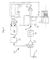
- the above-described monitoring system is improved as shown in Figure 2, in which similar or corresponding components are designated by the same reference numeral and which shows that said improved system, generally designated by the reference numeral 20', comprises an input amplifier 21' of the variable-gain type, driven by the signal that is present at the output of a digital/analog converter 25 which receives in input a datum supplied by the microprocessor ⁇ P.
- the microprocessor receives, on one of its inputs, a signal sa which originates from the feeder 11 and is proportional to the rotation rate W of the windmilling arm of the feeder and is programmed so that the signal that controls the gain G of the amplifier 21' varies substantially in inverse proportion to the signal sa related to the rotation rate W. Accordingly, the gain G of the amplifier 20' (and, correspondingly, the signal s4 applied to the comparator 24) vary as shown in the chart of Figure 2a, decreasing as the rotation rate W increases and increasing as said rate decreases.
- the microprocessor ⁇ P of the monitoring system 20'' is programmed so as to generate a datum VR which can vary in direct proportion to the signal sa that corresponds to the rotation rate W and is applied to a converter 25''.
- a datum VR'' expressed in voltage terms, which is adapted to be applied to the comparator 24, in order to supply a parametric comparison voltage which, as clearly shown in Figure 3a, is directly proportional to the rotation rate W of the feeder 11, i.e., it increases and decreases as said rotation rate increases and decreases.
Landscapes
- Engineering & Computer Science (AREA)
- Textile Engineering (AREA)
- Looms (AREA)
- Spinning Or Twisting Of Yarns (AREA)
- Treatment Of Fiber Materials (AREA)
Applications Claiming Priority (2)
| Application Number | Priority Date | Filing Date | Title |
|---|---|---|---|
| ITTO990204 | 1999-03-16 | ||
| IT1999TO000204 IT1308812B1 (it) | 1999-03-16 | 1999-03-16 | Metodo e dispositivo perfezionati di monitoraggio del filato di tramanei processi di tessitura e simili. |
Publications (2)
| Publication Number | Publication Date |
|---|---|
| EP1036869A1 true EP1036869A1 (de) | 2000-09-20 |
| EP1036869B1 EP1036869B1 (de) | 2004-02-25 |
Family
ID=11417631
Family Applications (1)
| Application Number | Title | Priority Date | Filing Date |
|---|---|---|---|
| EP20000104465 Expired - Lifetime EP1036869B1 (de) | 1999-03-16 | 2000-03-08 | Verfahren und Vorrichtung zur Überwachung von Schussfaden in Webverfahren oder dergleichen |
Country Status (3)
| Country | Link |
|---|---|
| EP (1) | EP1036869B1 (de) |
| DE (1) | DE60008443T2 (de) |
| IT (1) | IT1308812B1 (de) |
Cited By (2)
| Publication number | Priority date | Publication date | Assignee | Title |
|---|---|---|---|---|
| EP1445365A3 (de) * | 2003-01-22 | 2005-03-09 | Tsudakoma Kogyo Kabushiki Kaisha | Verfahren und Vorrichtung zum Detektieren des Schussfadens in einer Webmaschine |
| EP2075209A1 (de) * | 2007-12-28 | 2009-07-01 | L.G.L. Electronics S.p.A. | Vorrichtung zum Messen der Fadenspannung |
Citations (2)
| Publication number | Priority date | Publication date | Assignee | Title |
|---|---|---|---|---|
| EP0325793A1 (de) * | 1987-12-31 | 1989-08-02 | ROJ ELECTROTEX S.p.A. | Schussfadenwächter mit automatischem Einstellen des Verzuges für Schussfadenzuführer in schützenlosen Webmaschinen |
| EP0570875A2 (de) * | 1992-05-22 | 1993-11-24 | Picanol N.V. | Verfahren zum Ermitteln einer Kenngrösse für den Betrieb einer Webmaschine und Webmaschine zum Durchführen des Verfahrens |
-
1999
- 1999-03-16 IT IT1999TO000204 patent/IT1308812B1/it active
-
2000
- 2000-03-08 DE DE2000608443 patent/DE60008443T2/de not_active Expired - Lifetime
- 2000-03-08 EP EP20000104465 patent/EP1036869B1/de not_active Expired - Lifetime
Patent Citations (2)
| Publication number | Priority date | Publication date | Assignee | Title |
|---|---|---|---|---|
| EP0325793A1 (de) * | 1987-12-31 | 1989-08-02 | ROJ ELECTROTEX S.p.A. | Schussfadenwächter mit automatischem Einstellen des Verzuges für Schussfadenzuführer in schützenlosen Webmaschinen |
| EP0570875A2 (de) * | 1992-05-22 | 1993-11-24 | Picanol N.V. | Verfahren zum Ermitteln einer Kenngrösse für den Betrieb einer Webmaschine und Webmaschine zum Durchführen des Verfahrens |
Cited By (2)
| Publication number | Priority date | Publication date | Assignee | Title |
|---|---|---|---|---|
| EP1445365A3 (de) * | 2003-01-22 | 2005-03-09 | Tsudakoma Kogyo Kabushiki Kaisha | Verfahren und Vorrichtung zum Detektieren des Schussfadens in einer Webmaschine |
| EP2075209A1 (de) * | 2007-12-28 | 2009-07-01 | L.G.L. Electronics S.p.A. | Vorrichtung zum Messen der Fadenspannung |
Also Published As
| Publication number | Publication date |
|---|---|
| EP1036869B1 (de) | 2004-02-25 |
| DE60008443D1 (de) | 2004-04-01 |
| IT1308812B1 (it) | 2002-01-11 |
| ITTO990204A1 (it) | 2000-09-16 |
| DE60008443T2 (de) | 2005-01-13 |
Similar Documents
| Publication | Publication Date | Title |
|---|---|---|
| US4617971A (en) | Loom control system | |
| EP0097939B1 (de) | Schussfadenwächter für Düsenwebmaschinen | |
| EP2031106B1 (de) | Verfahren zur Spannungskontrolle eines Garnes, das von einem negativen Liefergerät an eine Textilmaschine geliefert wird, und Vorrichtung zur Durchführung des Verfahrens | |
| US8397582B2 (en) | Method for detecting the stop of the yarn unwinding from a yarn feeder provided with a stationary drum | |
| JP4651821B2 (ja) | 糸の走行/停止状態を監視する方法および糸検知器 | |
| US4023599A (en) | Opto-electronic weft yarn detector | |
| EP0713838B1 (de) | Vorrichtung und Verfahren zur Überwachung der Fadenreserve in Schussfadenliefervorrichtungen | |
| EP1036869B1 (de) | Verfahren und Vorrichtung zur Überwachung von Schussfaden in Webverfahren oder dergleichen | |
| US3673591A (en) | Yarn defect detector apparatus for textile machinery | |
| US4942909A (en) | Weft-feeder with automatic adjustment of the delay time, for weft feeders of shuttleless looms | |
| CN1046564C (zh) | 扫描纱线的方法和纱线退绕传感器 | |
| KR100446361B1 (ko) | 직물 방적사의 주행/정지 상태를 모니터하는 방법 | |
| US3494236A (en) | Circuit system for yarn rejection device | |
| JPH0680226B2 (ja) | 織機の緯糸密度監視装置 | |
| JPS63218475A (ja) | 糸切れ検出装置 | |
| JPS63145452A (ja) | 経糸群の異常検出装置 |
Legal Events
| Date | Code | Title | Description |
|---|---|---|---|
| PUAI | Public reference made under article 153(3) epc to a published international application that has entered the european phase |
Free format text: ORIGINAL CODE: 0009012 |
|
| AK | Designated contracting states |
Kind code of ref document: A1 Designated state(s): DE |
|
| AX | Request for extension of the european patent |
Free format text: AL;LT;LV;MK;RO;SI |
|
| 17P | Request for examination filed |
Effective date: 20010226 |
|
| AKX | Designation fees paid |
Free format text: DE |
|
| GRAP | Despatch of communication of intention to grant a patent |
Free format text: ORIGINAL CODE: EPIDOSNIGR1 |
|
| GRAS | Grant fee paid |
Free format text: ORIGINAL CODE: EPIDOSNIGR3 |
|
| GRAA | (expected) grant |
Free format text: ORIGINAL CODE: 0009210 |
|
| AK | Designated contracting states |
Kind code of ref document: B1 Designated state(s): DE |
|
| REF | Corresponds to: |
Ref document number: 60008443 Country of ref document: DE Date of ref document: 20040401 Kind code of ref document: P |
|
| PLBE | No opposition filed within time limit |
Free format text: ORIGINAL CODE: 0009261 |
|
| STAA | Information on the status of an ep patent application or granted ep patent |
Free format text: STATUS: NO OPPOSITION FILED WITHIN TIME LIMIT |
|
| 26N | No opposition filed |
Effective date: 20041126 |
|
| PGFP | Annual fee paid to national office [announced via postgrant information from national office to epo] |
Ref country code: DE Payment date: 20170327 Year of fee payment: 18 |
|
| REG | Reference to a national code |
Ref country code: DE Ref legal event code: R119 Ref document number: 60008443 Country of ref document: DE |
|
| PG25 | Lapsed in a contracting state [announced via postgrant information from national office to epo] |
Ref country code: DE Free format text: LAPSE BECAUSE OF NON-PAYMENT OF DUE FEES Effective date: 20181002 |