EP1036962A1 - Rastvorrichtung - Google Patents
Rastvorrichtung Download PDFInfo
- Publication number
- EP1036962A1 EP1036962A1 EP00102299A EP00102299A EP1036962A1 EP 1036962 A1 EP1036962 A1 EP 1036962A1 EP 00102299 A EP00102299 A EP 00102299A EP 00102299 A EP00102299 A EP 00102299A EP 1036962 A1 EP1036962 A1 EP 1036962A1
- Authority
- EP
- European Patent Office
- Prior art keywords
- locking
- selector shaft
- shaft
- elements
- cover
- Prior art date
- Legal status (The legal status is an assumption and is not a legal conclusion. Google has not performed a legal analysis and makes no representation as to the accuracy of the status listed.)
- Granted
Links
- 230000036316 preload Effects 0.000 claims 1
- 230000005540 biological transmission Effects 0.000 description 2
- 238000011161 development Methods 0.000 description 1
- 230000018109 developmental process Effects 0.000 description 1
- 230000002093 peripheral effect Effects 0.000 description 1
Images
Classifications
-
- F—MECHANICAL ENGINEERING; LIGHTING; HEATING; WEAPONS; BLASTING
- F16—ENGINEERING ELEMENTS AND UNITS; GENERAL MEASURES FOR PRODUCING AND MAINTAINING EFFECTIVE FUNCTIONING OF MACHINES OR INSTALLATIONS; THERMAL INSULATION IN GENERAL
- F16H—GEARING
- F16H63/00—Control outputs from the control unit to change-speed- or reversing-gearings for conveying rotary motion or to other devices than the final output mechanism
- F16H63/02—Final output mechanisms therefor; Actuating means for the final output mechanisms
- F16H63/30—Constructional features of the final output mechanisms
- F16H63/38—Detents
-
- F—MECHANICAL ENGINEERING; LIGHTING; HEATING; WEAPONS; BLASTING
- F16—ENGINEERING ELEMENTS AND UNITS; GENERAL MEASURES FOR PRODUCING AND MAINTAINING EFFECTIVE FUNCTIONING OF MACHINES OR INSTALLATIONS; THERMAL INSULATION IN GENERAL
- F16H—GEARING
- F16H63/00—Control outputs from the control unit to change-speed- or reversing-gearings for conveying rotary motion or to other devices than the final output mechanism
- F16H63/02—Final output mechanisms therefor; Actuating means for the final output mechanisms
- F16H63/30—Constructional features of the final output mechanisms
- F16H2063/3076—Selector shaft assembly, e.g. supporting, assembly or manufacturing of selector or shift shafts; Special details thereof
Definitions
- the present invention relates to a locking device for a shift shaft in one Manual transmission of a motor vehicle according to the preamble of patent claim 1.
- a generic locking device known from DE-OS 41 10 555 consists of two locking elements 16 and 18 (see FIG. 1 there), which are arranged on the circumference of a selector shaft 10 are arranged offset by 90 ° to each other. These two locking elements 16, 18 serve on the one hand for precise gear selection and on the other hand for precise shifting of one Switching device.
- Each locking element 16, 18 has a resiliently biased Snap ball on, each with one or more guides on the outer circumference of one Locking sleeve cooperates.
- the two locking elements 16 and 18 are at 90 ° staggered. Forces that on the locking elements 16 and 18 on the Actuate shift shaft, thereby stressing the bearing (s) of the shift shaft on one side and lead to an increased bearing load (friction).
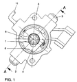
- FIG. 1 shows a switching device in cross section, in which a switching shaft 1, perpendicular to the plane of the drawing, is arranged.
- a shift finger 6 attacks the control shaft 1.
- a detent sleeve 4 is arranged around the selector shaft 1, which has depressions or guides on the outer circumference, which have locking elements 2 and 3 of the locking device can be brought into engagement.
- the locking elements 2 and 3 run through a cover 5 of the switching device and are each pressed into an opening 7.
- the locking element 2 is for switching or the switching direction of the switching shaft 1 is provided while the locking element 3 for the selection (of the gears) or the selection direction is provided.
- Each locking element 2 or 3 has a locking ball 8 preloaded by spring force, with the guides mentioned above on the outer circumference of the locking sleeve 4th interacts.
- the two Latching elements 2 and 3 on the selector shaft 1 are arranged diametrically opposite one another, so that the forces exerted by the locking elements 2 and 3 on the selector shaft 1 applied, cancel each other out.
- the load on the bearing of the selector shaft 1 is reduced by this measure, since between the locking elements 2 and 3 There is a balance of forces.
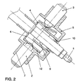
- the control shaft 1 is passed through the cover 5 (see FIG. 2) and between the cover 5 and the control shaft 1, a seal 10 is provided. Between the Switch shaft 1 and the cover 5, a sliding bush 9 is provided.
- the sliding bush 9 is preferably greased when assembling the switching device.
- a Locking 11 passes through the cover 5 of the switching device.
- the locking element 2 is in contact with its locking ball 8 a recess 12 in the locking sleeve 4, this recess 12 after the Sectional representation in Figure 2 is a linear extension (perpendicular to Drawing level in Figure 1).
- the locking element 3 lies on one under one obtuse angle kinked (see Figure 2) extending outer peripheral surface of the Locking sleeve 4 on.
- This design of the locking device ensures that that the forces exerted by the two locking elements on the selector shaft become, cancel each other out and that thereby the burden for the storage of the Switching shaft is reduced, whereby their functionality is preserved and their Life is extended.
Landscapes
- Engineering & Computer Science (AREA)
- General Engineering & Computer Science (AREA)
- Mechanical Engineering (AREA)
- Gear-Shifting Mechanisms (AREA)
- Lock And Its Accessories (AREA)
- Clamps And Clips (AREA)
Abstract
Description
- 1
- Schaltwelle
- 2
- Rastelement (Schaltrichtung)
- 3
- Rastelement (Wählrichtung)
- 4
- Rastierhülse
- 5
- Deckel
- 6
- Schaltfinger
- 7
- Öffnung(en)
- 8
- Rastkugel
- 9
- Gleitbuchse
- 10
- Dichtung
- 11
- Arretierung
- 12
- Vertiefung
Claims (7)
- Rastvorrichtung für eine Schaltwelle (1) eines Schaltgetriebes eines Kraftfahrzeuges, mit zwei am Umfang der Schaltwelle (1) angeordneten Rastelementen (2, 3), die federnd gegen eine Rastierhülse (4) vorgespannt sind,
dadurch gekennzeichnet, daß
die beiden Rastelemente (2, 3) um im wesentlichen 180° gegeneinander versetzt an der Schaltwelle (1) angeordnet sind. - Rastvorrichtung nach Anspruch 1, dadurch gekennzeichnet, daß die sich aus der Vorspannung bzw. Federbelastung der Rastelemente (2, 3) ergebenden Kräfte an der Schaltwelle (1) im wesentlichen aufheben.
- Rastvorrichtung nach Anspruch 1 oder 2, dadurch gekennzeichnet, daß das Rastelement (2) für die Schaltrichtung und das Rastelement (3) für die Wählrichtung der Schaltwelle (1) vorgesehen ist.
- Rastvorrichtung nach einem der Ansprüche 1 bis 3, dadurch gekennzeichnet, daß die Rastelemente (2, 3) als Arretierschrauben ausgebildet sind.
- Rastvorrichtung nach Anspruch 4, dadurch gekennzeichnet, daß die Arretierschrauben am Deckel (5) einer Schaltvorrichtung vorgesehen sind.
- Rastvorrichtung nach einem der Ansprüche 1 bis 5, dadurch gekennzeichnet, daß zwischen dem Deckel (5) und der Schaltwelle (1) eine Dichtung (10) vorgesehen ist.
- Rastvorrichtung nach einem der Ansprüche 1 bis 6, dadurch gekennzeichnet, daß zwischen der Schaltwelle (1) und dem Deckel (5) eine Gleitbuchse (9) vorgesehen ist.
Applications Claiming Priority (2)
| Application Number | Priority Date | Filing Date | Title |
|---|---|---|---|
| DE19911662 | 1999-03-16 | ||
| DE19911662A DE19911662A1 (de) | 1999-03-16 | 1999-03-16 | Rastvorrichtung |
Publications (2)
| Publication Number | Publication Date |
|---|---|
| EP1036962A1 true EP1036962A1 (de) | 2000-09-20 |
| EP1036962B1 EP1036962B1 (de) | 2003-09-24 |
Family
ID=7901150
Family Applications (1)
| Application Number | Title | Priority Date | Filing Date |
|---|---|---|---|
| EP00102299A Expired - Lifetime EP1036962B1 (de) | 1999-03-16 | 2000-02-17 | Rastvorrichtung |
Country Status (4)
| Country | Link |
|---|---|
| EP (1) | EP1036962B1 (de) |
| CN (1) | CN1205429C (de) |
| AT (1) | ATE250733T1 (de) |
| DE (2) | DE19911662A1 (de) |
Cited By (6)
| Publication number | Priority date | Publication date | Assignee | Title |
|---|---|---|---|---|
| DE10143360A1 (de) * | 2001-09-04 | 2003-03-27 | Ina Schaeffler Kg | Schalteinrichtung |
| FR2844568A1 (fr) * | 2002-09-13 | 2004-03-19 | Peugeot Citroen Automobiles Sa | Dispositif de commande de boites de vitesses a couple de rappel compense |
| WO2004029486A1 (de) * | 2002-09-21 | 2004-04-08 | Adam Opel Ag | Fuehrungsmechanismus für eine schaltbewegung in einem schaltgetriebe |
| WO2008003407A1 (de) * | 2006-07-07 | 2008-01-10 | Gm Global Technology Operations, Inc. | Schaltgetriebe |
| CN103185136A (zh) * | 2011-12-29 | 2013-07-03 | 格特拉克·福特传动系统有限公司 | 用于换档变速器的换档装置 |
| EP3396214A1 (de) * | 2017-04-27 | 2018-10-31 | DURA Automotive Holdings U.K., Ltd. | Schaltfinger mit doppelter kugelverriegelung |
Families Citing this family (5)
| Publication number | Priority date | Publication date | Assignee | Title |
|---|---|---|---|---|
| DE102010017359A1 (de) * | 2010-06-14 | 2011-12-15 | Koki Technik Transmission Systems Gmbh | Betätigungsvorrichtung für ein Schaltgetriebe |
| DE102013214963B4 (de) * | 2013-07-31 | 2015-10-01 | Schaeffler Technologies AG & Co. KG | Schalteinheit für ein Kraftfahrzeuggetriebe |
| CN104033585B (zh) * | 2014-05-28 | 2016-04-27 | 浙江一铭机车部件有限公司 | 一种用于汽车变速箱的换档轴总成 |
| DE102014107767B3 (de) * | 2014-06-03 | 2015-10-01 | Jopp Holding GmbH | Schaltwellenmodul zum Schalten von Gängen in einem Schaltgetriebe |
| CN107023679B (zh) * | 2016-01-30 | 2019-03-01 | 长城汽车股份有限公司 | 变速器挡位互锁机构 |
Citations (6)
| Publication number | Priority date | Publication date | Assignee | Title |
|---|---|---|---|---|
| DE1114093B (de) * | 1958-09-11 | 1961-09-21 | Tatra Np | Entlastungsvorrichtung fuer die Schaltvorrichtung eines synchronisierten Wechselgetriebes, insbesondere fuer Kraftfahrzeuge |
| DE7735295U1 (de) * | 1977-11-18 | 1978-02-23 | Bayerische Motoren Werke Ag, 8000 Muenchen | Schaltvorrichtung fuer zahnradwechselgetriebe von kraftfahrzeugen, insbesondere von personenkraftwagen |
| FR2365841A1 (fr) * | 1976-09-25 | 1978-04-21 | Zahnradfabrik Friedrichshafen | Dispositif de manoeuvre pour mecanisme de changement de vitesse a engrenages compose d'une boite principale et d'une boite auxiliaire a deux rapports |
| JPH03255269A (ja) * | 1990-03-02 | 1991-11-14 | Jidosha Kiki Co Ltd | 変速機操作装置 |
| DE4110555A1 (de) * | 1991-03-30 | 1992-10-01 | Audi Ag | Schaltvorrichtung fuer geschwindigkeits-wechselgetriebe |
| EP0903518A2 (de) * | 1997-09-20 | 1999-03-24 | Ford Global Technologies, Inc., A subsidiary of Ford Motor Company | Schaltvorrichtung für ein Wechselgetriebe von Kraftfahrzeugen |
Family Cites Families (2)
| Publication number | Priority date | Publication date | Assignee | Title |
|---|---|---|---|---|
| DE3432401A1 (de) * | 1983-09-13 | 1985-03-28 | Zahnradfabrik Friedrichshafen Ag, 7990 Friedrichshafen | Waehlrastierung in einer gangschalteinrichtung |
| DE4421534A1 (de) * | 1994-06-20 | 1995-12-21 | Schaeffler Waelzlager Kg | Rastvorrichtung |
-
1999
- 1999-03-16 DE DE19911662A patent/DE19911662A1/de not_active Withdrawn
-
2000
- 2000-02-17 AT AT00102299T patent/ATE250733T1/de not_active IP Right Cessation
- 2000-02-17 EP EP00102299A patent/EP1036962B1/de not_active Expired - Lifetime
- 2000-02-17 DE DE50003780T patent/DE50003780D1/de not_active Expired - Lifetime
- 2000-03-16 CN CNB001176013A patent/CN1205429C/zh not_active Expired - Lifetime
Patent Citations (6)
| Publication number | Priority date | Publication date | Assignee | Title |
|---|---|---|---|---|
| DE1114093B (de) * | 1958-09-11 | 1961-09-21 | Tatra Np | Entlastungsvorrichtung fuer die Schaltvorrichtung eines synchronisierten Wechselgetriebes, insbesondere fuer Kraftfahrzeuge |
| FR2365841A1 (fr) * | 1976-09-25 | 1978-04-21 | Zahnradfabrik Friedrichshafen | Dispositif de manoeuvre pour mecanisme de changement de vitesse a engrenages compose d'une boite principale et d'une boite auxiliaire a deux rapports |
| DE7735295U1 (de) * | 1977-11-18 | 1978-02-23 | Bayerische Motoren Werke Ag, 8000 Muenchen | Schaltvorrichtung fuer zahnradwechselgetriebe von kraftfahrzeugen, insbesondere von personenkraftwagen |
| JPH03255269A (ja) * | 1990-03-02 | 1991-11-14 | Jidosha Kiki Co Ltd | 変速機操作装置 |
| DE4110555A1 (de) * | 1991-03-30 | 1992-10-01 | Audi Ag | Schaltvorrichtung fuer geschwindigkeits-wechselgetriebe |
| EP0903518A2 (de) * | 1997-09-20 | 1999-03-24 | Ford Global Technologies, Inc., A subsidiary of Ford Motor Company | Schaltvorrichtung für ein Wechselgetriebe von Kraftfahrzeugen |
Non-Patent Citations (1)
| Title |
|---|
| PATENT ABSTRACTS OF JAPAN vol. 016, no. 057 (M - 1210) 13 February 1992 (1992-02-13) * |
Cited By (8)
| Publication number | Priority date | Publication date | Assignee | Title |
|---|---|---|---|---|
| DE10143360A1 (de) * | 2001-09-04 | 2003-03-27 | Ina Schaeffler Kg | Schalteinrichtung |
| DE10143360B4 (de) * | 2001-09-04 | 2011-04-28 | Schaeffler Technologies Gmbh & Co. Kg | Schalteinrichtung |
| FR2844568A1 (fr) * | 2002-09-13 | 2004-03-19 | Peugeot Citroen Automobiles Sa | Dispositif de commande de boites de vitesses a couple de rappel compense |
| EP1398545A3 (de) * | 2002-09-13 | 2009-12-30 | Peugeot Citroen Automobiles SA | Schaltvorrichtung für Wechselgetriebe mit kraftkompensierter Rückstellvorrichtung |
| WO2004029486A1 (de) * | 2002-09-21 | 2004-04-08 | Adam Opel Ag | Fuehrungsmechanismus für eine schaltbewegung in einem schaltgetriebe |
| WO2008003407A1 (de) * | 2006-07-07 | 2008-01-10 | Gm Global Technology Operations, Inc. | Schaltgetriebe |
| CN103185136A (zh) * | 2011-12-29 | 2013-07-03 | 格特拉克·福特传动系统有限公司 | 用于换档变速器的换档装置 |
| EP3396214A1 (de) * | 2017-04-27 | 2018-10-31 | DURA Automotive Holdings U.K., Ltd. | Schaltfinger mit doppelter kugelverriegelung |
Also Published As
| Publication number | Publication date |
|---|---|
| CN1205429C (zh) | 2005-06-08 |
| EP1036962B1 (de) | 2003-09-24 |
| ATE250733T1 (de) | 2003-10-15 |
| CN1269298A (zh) | 2000-10-11 |
| DE50003780D1 (de) | 2003-10-30 |
| DE19911662A1 (de) | 2000-09-21 |
Similar Documents
| Publication | Publication Date | Title |
|---|---|---|
| EP0223921B1 (de) | Parksperre für automatische Getriebe von Kraftfahrzeugen | |
| EP0903518B1 (de) | Schaltvorrichtung für ein Wechselgetriebe von Kraftfahrzeugen | |
| DE4015699C2 (de) | ||
| DE3116833C2 (de) | Vorrichtung zum wahlweisen Einrücken einer Vielzahl von Gängen in einem manuell schaltbaren Getriebe | |
| EP0731885B1 (de) | Schaltvorrichtung | |
| EP2029385B1 (de) | Schaltvorrichtung für ein getriebe | |
| EP1036962B1 (de) | Rastvorrichtung | |
| EP2035263B1 (de) | Betätigungselement für die parksperre eines getriebes und parksperre für ein getriebe | |
| DE10156392A1 (de) | Gangschaltvorrichtung für ein mehrstufiges Getriebe eines Elektrowerkzeugs | |
| DE19509477A1 (de) | Schaltvorrichtung für ein Geschwindigkeits-Wechselgetriebe | |
| DE2843456C2 (de) | Stellungsgeber zum Beeinflussen der Fahrgeschwindigkeit eines Kraftfahrzeugs | |
| EP0849506A1 (de) | Federelement zur Wählkrafterzeugung für ein mehrgängiges Zahnräderwechselgetriebe | |
| DE3016909C2 (de) | Schaltvorrichtung für ein mehrgängiges Zahnräder-Wechselgetriebe | |
| DE4127098A1 (de) | Gangschaltung eines kraftfahrzeuggetriebes | |
| EP0895007B1 (de) | Schaltkulisse für einen an einer Schaltwelle angeordneten Schaltstift eines Wechselgetriebes | |
| DE10315138A1 (de) | Schaltbares Getriebe einer handgeführten Werkzeugmaschine | |
| EP0819573A1 (de) | Kopfstützen-Arretiereinrichtung | |
| EP0999384A1 (de) | Schaltvorrichtung für Wechselgetriebe von Kraftfahrzeugen | |
| DE3603609C2 (de) | ||
| DE4442120A1 (de) | Rampenkontur für eine Arretiereinrichtung | |
| CH660410A5 (de) | Mehrwege-hahn. | |
| DE4428557A1 (de) | Drehgelenk | |
| EP0790443A2 (de) | Schaltvorrichtung ohne Leergangbewegung während einer Einrückbewegung des Rückwärtsganges | |
| EP1258660B1 (de) | Schaltvorrichtung eines Schaltgetriebes | |
| DE4122677A1 (de) | Schalteinrichtung fuer ein getriebe, insbesondere wechselgetriebe fuer kraftfahrzeuge |
Legal Events
| Date | Code | Title | Description |
|---|---|---|---|
| PUAI | Public reference made under article 153(3) epc to a published international application that has entered the european phase |
Free format text: ORIGINAL CODE: 0009012 |
|
| AK | Designated contracting states |
Kind code of ref document: A1 Designated state(s): AT BE CH CY DE DK ES FI FR GB GR IE IT LI LU MC NL PT SE |
|
| AX | Request for extension of the european patent |
Free format text: AL;LT;LV;MK;RO;SI |
|
| 17P | Request for examination filed |
Effective date: 20010320 |
|
| AKX | Designation fees paid |
Free format text: AT BE CH CY DE DK ES FI FR GB GR IE IT LI LU MC NL PT SE |
|
| 17Q | First examination report despatched |
Effective date: 20020723 |
|
| GRAH | Despatch of communication of intention to grant a patent |
Free format text: ORIGINAL CODE: EPIDOS IGRA |
|
| GRAS | Grant fee paid |
Free format text: ORIGINAL CODE: EPIDOSNIGR3 |
|
| GRAA | (expected) grant |
Free format text: ORIGINAL CODE: 0009210 |
|
| AK | Designated contracting states |
Kind code of ref document: B1 Designated state(s): AT BE CH CY DE DK ES FI FR GB GR IE IT LI LU MC NL PT SE |
|
| PG25 | Lapsed in a contracting state [announced via postgrant information from national office to epo] |
Ref country code: IE Free format text: LAPSE BECAUSE OF FAILURE TO SUBMIT A TRANSLATION OF THE DESCRIPTION OR TO PAY THE FEE WITHIN THE PRESCRIBED TIME-LIMIT Effective date: 20030924 Ref country code: FI Free format text: LAPSE BECAUSE OF FAILURE TO SUBMIT A TRANSLATION OF THE DESCRIPTION OR TO PAY THE FEE WITHIN THE PRESCRIBED TIME-LIMIT Effective date: 20030924 Ref country code: IT Free format text: LAPSE BECAUSE OF FAILURE TO SUBMIT A TRANSLATION OF THE DESCRIPTION OR TO PAY THE FEE WITHIN THE PRESCRIBED TIME-LIMIT;WARNING: LAPSES OF ITALIAN PATENTS WITH EFFECTIVE DATE BEFORE 2007 MAY HAVE OCCURRED AT ANY TIME BEFORE 2007. THE CORRECT EFFECTIVE DATE MAY BE DIFFERENT FROM THE ONE RECORDED. Effective date: 20030924 Ref country code: GB Free format text: LAPSE BECAUSE OF FAILURE TO SUBMIT A TRANSLATION OF THE DESCRIPTION OR TO PAY THE FEE WITHIN THE PRESCRIBED TIME-LIMIT Effective date: 20030924 Ref country code: NL Free format text: LAPSE BECAUSE OF FAILURE TO SUBMIT A TRANSLATION OF THE DESCRIPTION OR TO PAY THE FEE WITHIN THE PRESCRIBED TIME-LIMIT Effective date: 20030924 Ref country code: CY Free format text: LAPSE BECAUSE OF FAILURE TO SUBMIT A TRANSLATION OF THE DESCRIPTION OR TO PAY THE FEE WITHIN THE PRESCRIBED TIME-LIMIT Effective date: 20030924 |
|
| REG | Reference to a national code |
Ref country code: GB Ref legal event code: FG4D Free format text: NOT ENGLISH |
|
| REG | Reference to a national code |
Ref country code: CH Ref legal event code: EP |
|
| REG | Reference to a national code |
Ref country code: IE Ref legal event code: FG4D Free format text: GERMAN |
|
| REF | Corresponds to: |
Ref document number: 50003780 Country of ref document: DE Date of ref document: 20031030 Kind code of ref document: P |
|
| PG25 | Lapsed in a contracting state [announced via postgrant information from national office to epo] |
Ref country code: DK Free format text: LAPSE BECAUSE OF FAILURE TO SUBMIT A TRANSLATION OF THE DESCRIPTION OR TO PAY THE FEE WITHIN THE PRESCRIBED TIME-LIMIT Effective date: 20031224 Ref country code: GR Free format text: LAPSE BECAUSE OF FAILURE TO SUBMIT A TRANSLATION OF THE DESCRIPTION OR TO PAY THE FEE WITHIN THE PRESCRIBED TIME-LIMIT Effective date: 20031224 Ref country code: SE Free format text: LAPSE BECAUSE OF FAILURE TO SUBMIT A TRANSLATION OF THE DESCRIPTION OR TO PAY THE FEE WITHIN THE PRESCRIBED TIME-LIMIT Effective date: 20031224 |
|
| PG25 | Lapsed in a contracting state [announced via postgrant information from national office to epo] |
Ref country code: ES Free format text: LAPSE BECAUSE OF FAILURE TO SUBMIT A TRANSLATION OF THE DESCRIPTION OR TO PAY THE FEE WITHIN THE PRESCRIBED TIME-LIMIT Effective date: 20040104 |
|
| PG25 | Lapsed in a contracting state [announced via postgrant information from national office to epo] |
Ref country code: LU Free format text: LAPSE BECAUSE OF NON-PAYMENT OF DUE FEES Effective date: 20040217 Ref country code: AT Free format text: LAPSE BECAUSE OF NON-PAYMENT OF DUE FEES Effective date: 20040217 |
|
| PG25 | Lapsed in a contracting state [announced via postgrant information from national office to epo] |
Ref country code: MC Free format text: LAPSE BECAUSE OF NON-PAYMENT OF DUE FEES Effective date: 20040228 Ref country code: BE Free format text: LAPSE BECAUSE OF NON-PAYMENT OF DUE FEES Effective date: 20040228 |
|
| PG25 | Lapsed in a contracting state [announced via postgrant information from national office to epo] |
Ref country code: CH Free format text: LAPSE BECAUSE OF NON-PAYMENT OF DUE FEES Effective date: 20040229 Ref country code: LI Free format text: LAPSE BECAUSE OF NON-PAYMENT OF DUE FEES Effective date: 20040229 |
|
| NLV1 | Nl: lapsed or annulled due to failure to fulfill the requirements of art. 29p and 29m of the patents act | ||
| GBV | Gb: ep patent (uk) treated as always having been void in accordance with gb section 77(7)/1977 [no translation filed] |
Effective date: 20030924 |
|
| REG | Reference to a national code |
Ref country code: IE Ref legal event code: FD4D |
|
| ET | Fr: translation filed | ||
| PLBE | No opposition filed within time limit |
Free format text: ORIGINAL CODE: 0009261 |
|
| STAA | Information on the status of an ep patent application or granted ep patent |
Free format text: STATUS: NO OPPOSITION FILED WITHIN TIME LIMIT |
|
| BERE | Be: lapsed |
Owner name: *VOLKSWAGEN A.G. Effective date: 20040228 |
|
| 26N | No opposition filed |
Effective date: 20040625 |
|
| REG | Reference to a national code |
Ref country code: CH Ref legal event code: PL |
|
| PG25 | Lapsed in a contracting state [announced via postgrant information from national office to epo] |
Ref country code: PT Free format text: LAPSE BECAUSE OF NON-PAYMENT OF DUE FEES Effective date: 20040224 |
|
| REG | Reference to a national code |
Ref country code: FR Ref legal event code: PLFP Year of fee payment: 17 |
|
| PGFP | Annual fee paid to national office [announced via postgrant information from national office to epo] |
Ref country code: FR Payment date: 20160229 Year of fee payment: 17 |
|
| REG | Reference to a national code |
Ref country code: FR Ref legal event code: ST Effective date: 20171031 |
|
| PG25 | Lapsed in a contracting state [announced via postgrant information from national office to epo] |
Ref country code: FR Free format text: LAPSE BECAUSE OF NON-PAYMENT OF DUE FEES Effective date: 20170228 |
|
| PGFP | Annual fee paid to national office [announced via postgrant information from national office to epo] |
Ref country code: DE Payment date: 20190228 Year of fee payment: 20 |
|
| PGFP | Annual fee paid to national office [announced via postgrant information from national office to epo] |
Ref country code: DE Payment date: 20190228 Year of fee payment: 20 |
|
| REG | Reference to a national code |
Ref country code: DE Ref legal event code: R071 Ref document number: 50003780 Country of ref document: DE |
|
| P01 | Opt-out of the competence of the unified patent court (upc) registered |
Effective date: 20230523 |