EP1037367B1 - Spannungserhöhungsschaltung, Spannungserhöhungsverfahren, und elektronisches Gerät - Google Patents
Spannungserhöhungsschaltung, Spannungserhöhungsverfahren, und elektronisches Gerät Download PDFInfo
- Publication number
- EP1037367B1 EP1037367B1 EP00301991A EP00301991A EP1037367B1 EP 1037367 B1 EP1037367 B1 EP 1037367B1 EP 00301991 A EP00301991 A EP 00301991A EP 00301991 A EP00301991 A EP 00301991A EP 1037367 B1 EP1037367 B1 EP 1037367B1
- Authority
- EP
- European Patent Office
- Prior art keywords
- voltage
- charge
- terminal
- boost
- accumulating device
- Prior art date
- Legal status (The legal status is an assumption and is not a legal conclusion. Google has not performed a legal analysis and makes no representation as to the accuracy of the status listed.)
- Expired - Lifetime
Links
- 238000000034 method Methods 0.000 title claims description 9
- 239000003990 capacitor Substances 0.000 description 98
- 239000004973 liquid crystal related substance Substances 0.000 description 17
- 238000010586 diagram Methods 0.000 description 9
- 238000001514 detection method Methods 0.000 description 4
- 238000005401 electroluminescence Methods 0.000 description 3
- 239000011159 matrix material Substances 0.000 description 2
- 239000010409 thin film Substances 0.000 description 2
- 230000005540 biological transmission Effects 0.000 description 1
- 230000001413 cellular effect Effects 0.000 description 1
- 230000007423 decrease Effects 0.000 description 1
- 230000002542 deteriorative effect Effects 0.000 description 1
- 238000009499 grossing Methods 0.000 description 1
- 239000004065 semiconductor Substances 0.000 description 1
- 239000000758 substrate Substances 0.000 description 1
Images




Classifications
-
- H—ELECTRICITY
- H02—GENERATION; CONVERSION OR DISTRIBUTION OF ELECTRIC POWER
- H02M—APPARATUS FOR CONVERSION BETWEEN AC AND AC, BETWEEN AC AND DC, OR BETWEEN DC AND DC, AND FOR USE WITH MAINS OR SIMILAR POWER SUPPLY SYSTEMS; CONVERSION OF DC OR AC INPUT POWER INTO SURGE OUTPUT POWER; CONTROL OR REGULATION THEREOF
- H02M7/00—Conversion of AC power input into DC power output; Conversion of DC power input into AC power output
- H02M7/02—Conversion of AC power input into DC power output without possibility of reversal
- H02M7/04—Conversion of AC power input into DC power output without possibility of reversal by static converters
- H02M7/06—Conversion of AC power input into DC power output without possibility of reversal by static converters using discharge tubes without control electrode or semiconductor devices without control electrode
- H02M7/10—Conversion of AC power input into DC power output without possibility of reversal by static converters using discharge tubes without control electrode or semiconductor devices without control electrode arranged for operation in series, e.g. for multiplication of voltage
-
- H—ELECTRICITY
- H02—GENERATION; CONVERSION OR DISTRIBUTION OF ELECTRIC POWER
- H02M—APPARATUS FOR CONVERSION BETWEEN AC AND AC, BETWEEN AC AND DC, OR BETWEEN DC AND DC, AND FOR USE WITH MAINS OR SIMILAR POWER SUPPLY SYSTEMS; CONVERSION OF DC OR AC INPUT POWER INTO SURGE OUTPUT POWER; CONTROL OR REGULATION THEREOF
- H02M3/00—Conversion of DC power input into DC power output
- H02M3/02—Conversion of DC power input into DC power output without intermediate conversion into AC
- H02M3/04—Conversion of DC power input into DC power output without intermediate conversion into AC by static converters
- H02M3/06—Conversion of DC power input into DC power output without intermediate conversion into AC by static converters using resistors or capacitors, e.g. potential divider
- H02M3/07—Conversion of DC power input into DC power output without intermediate conversion into AC by static converters using resistors or capacitors, e.g. potential divider using capacitors charged and discharged alternately by semiconductor devices with control electrode, e.g. charge pumps
Definitions
- the present invention relates to voltage booster circuits and voltage boosting methods which reduce the number of charge-accumulating devices required for a voltage boost and electronic units using the output of such a voltage booster circuit as a power source.
- a high-voltage power source is required to drive liquid-crystal devices in order to obtain successful display characteristics. Therefore, a power-source circuit used in the liquid-crystal display apparatuses is configured such that an input voltage is boosted by a voltage booster circuit and the boosted voltage is supplied to a driving circuit for driving the liquid-crystal devices and to other circuits.
- Fig. 13 is a circuit diagram showing the configuration of a voltage booster circuit 138 in this case.
- the voltage booster circuit 138 is formed of transistors Q1 to Q8, auxiliary capacitors C1, C2, and C2p, and an output capacitor Cout.
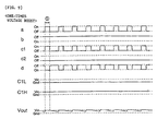
- Fig. 14 is a timing chart of control signals sent to the voltage booster circuit 138.
- a control signal “a” shown in this figure is generated by narrowing the pulse width of a control signal "b,” and is sent to n-channel transistors Q2, Q4, Q6, and Q8 in the voltage booster circuit 138 as gate signals.
- a control signal "b” is supplied to p-channel transistors Q1, Q3, Q5 and Q7 of the voltage-booster circuit 138 as the gate signal.
- transistors Q2, Q4, Q6, and Q8 are turned on whereas the other transistors are turned off in a period indicated by 1 ⁇ in Fig. 14, that is, a period in which only the control signal "a” has an "H” level. Therefore, the auxiliary capacitor C1 is charged with an input voltage Vin since a terminal C1H is connected to the supply line of the input voltage Vin and a terminal C1L is connected to the ground line, as shown in 1 ⁇ of Fig. 15.
- the auxiliary capacitor C2 is connected in parallel to the auxiliary capacitor C2p charged with 2Vin, in a period indicated by 2 ⁇ , and is charged. After these operations, all the transistors Q1 to Q8 are turned off temporarily.
- the auxiliary capacitor C2p since a terminal C2pH of the auxiliary capacitor C2p is connected to the terminal C1H, the auxiliary capacitor C2p is charged with a potential difference of 2Vin. Therefore, the potential of the terminal C2pH becomes 2Vin in the period 2 ⁇ .
- the terminal C1H is connected to a terminal C2L of the auxiliary capacitor C2, which has been charged with 2Vin in the period 2 ⁇ , the potential of the terminal C2H of the auxiliary capacitor C2 becomes 4Vin, which is offset from the potential of the terminal C1H (C2pH, C2L), 2Vin, to a higher potential by the output voltage 2Vin of the auxiliary capacitor C2. And then, the potential is smoothed by the output capacitor Cout. With the periods 1 ⁇ and 2 ⁇ being repeated in this way, the input voltage Vin is boosted four times and outputted.
- auxiliary capacitors C1, C2, C2p, C3, C3p, C4, and C4p are used, as shown in Fig. 16.
- the auxiliary capacitor C1 is charged with an input voltage Vin
- the auxiliary capacitor C2 is connected in parallel to the auxiliary capacitor C2p which has been charged with 2Vin in 2 ⁇ and is charged
- the auxiliary capacitor C3 is connected in parallel to the auxiliary capacitor C3p which has been charged with 4Vin in 2 ⁇ and is charged in the same way
- the auxiliary capacitor C4 is connected in parallel to the auxiliary capacitor C4p which has been charged with 8Vin in 2 ⁇ and is charged in the same way.
- the auxiliary capacitor C2p is first charged with 2Vin, which is offset from the input voltage Vin to a higher potential by the output voltage Vin of the auxiliary capacitor C1; secondly, the auxiliary capacitor C3p is charged with 4Vin, which is offset from a potential of 2Vin caused by the auxiliary capacitor C1 to a higher potential by the output voltage 2Vin of the auxiliary capacitor C2; thirdly, the auxiliary capacitor C4p is charged with 8Vin, which is offset from a potential of 4Vin caused by the auxiliary capacitor C2 to a higher potential by the output voltage 4Vin of the auxiliary capacitor C3; and fourthly, a potential of 16Vin, which is 16 times the input voltage Vin, is obtained by offsetting a potential of 8Vin caused by the auxiliary capacitor C3 to a higher potential by the output voltage 8Vin of the auxiliary capacitor C4.
- the largest problem in the conventional voltage booster circuit is that it is difficult to control the voltage-boost magnification as required. Therefore, to make the boosted voltage constant at the desired voltage value, a separate constant-voltage circuit such as a switching regulator is required at a later stage in the voltage booster circuit, and accordingly, the scale of the power-source circuit becomes large.
- US 5870295 discloses a voltage booster circuit comprising:
- the present invention has been made in consideration of the above situations. Accordingly, it is an object of the present invention to provide a voltage booster circuit and a voltage boosting method which allow the voltage-boost magnification to be controlled relatively freely, and to provide an electronic unit using the output of the voltage booster circuit as a power source.
- a voltage booster circuit comprises: voltage booster circuit comprising:
- the other terminal of the first charge-accumulating device since the first charge-accumulating device is connected between the first and the second lines, the other terminal of the first charge-accumulating device has the same potential as the second line when it is assumed that the first line has a reference potential.
- the one terminal of the first charge-accumulating device is switched from the first line to the second line, since the potential of the other terminal of the first charge-accumulating device is offset from the potential of the second line in the potential direction opposite to that to the first line by the output voltage of the first charge-accumulating device, which is twice the potential of the second line, and the second charge-accumulating device is charged therewith.
- the potential of the output line becomes four times the potential of the second line, which is offset from the potential of the other terminal of the first charge-accumulating device, having a potential that is twice the potential of the second line, in the potential direction opposite to that to the first line by the output voltage of the second charge-accumulating device. Therefore, two charge-accumulating devices are required to boost the potential difference between the first and the second lines four times.
- Such a configuration can be used in a case when the first line has a higher potential than the second line as well as in a case when the first line has a lower potential than the second line.
- the reference potential may be the potential of the first line or that of the second line.
- said voltage boost control circuit is arranged for controlling whether the connection of the second charge-accumulating device is established by said second connection means in the first arrangement or said fourth connection means in the second arrangement.
- the control means controls such that the connection period of the second charge-accumulating device established by the second connection means is set to the entire period and the connection period of the second charge-accumulating device established by the fourth connection means is set to zero, the potential of the output line becomes four times the potential of the second line as described above.
- the control means controls such that the connection period of the second charge-accumulating device established by the second connection means is set to zero and the connection period of the second charge-accumulating device established by the fourth connection means is set to the entire period, since the output voltage of the second charge-accumulating device becomes equal to, not two times, the potential difference between the first line and the second line, the potential of the output line becomes three times the potential of the second line. Therefore, when the potential of the output line is smoothed with the connection-period ratio being controlled, the voltage-boost magnification can be varied to any value between three and four.
- said voltage boost control circuit controls such that the connection period of the second charge-accumulating device established by said second connection means in the first arrangement is longer than the connection period of the second charge-accumulating device established by said fourth connection means in the second arrangement when the potential of the second line or a potential according to the output line is lower in absolute values than a predetermined value.
- the potential of the output line can be made constant between three times and four times the potential of the second line.
- said voltage boost control circuit is arranged for controlling whether the connection of the second charge-accumulating device is established by said second and fourth connection means in the first and second arrangements respectively or the connection is established by said fifth connection means in the third arrangement.
- the control means controls such that the connection period of the second charge-accumulating device established by the second or the fourth connection means is set to the entire period and the connection period of the second charge-accumulating device established by the fifth connection means is set to zero, the potential of the output line becomes four times or three times the potential of the second line as described above.
- the control means controls such that the connection period of the second charge-accumulating device established by the second or the fourth connection means is set to zero and the connection period of the second charge-accumulating device established by the fifth connection means is set to the entire period
- the output line has the same potential as the other terminal of the first charge-accumulating device, having a potential that is two times the potential of the second line. Therefore, when the potential of the output line is smoothed with the connection-period ratio being controlled, the voltage-boost magnification can be varied to any value between four and two, or between three and two.
- said voltage boost control circuit controls such that the connection period of the second charge-accumulating device established by said second and fourth connection means in the first and second arrangements respectively is longer than the connection period established by said fifth connection means in the third arrangement when the potential of the second line or a potential according to the output line is lower in absolute values than a predetermined value.
- the potential of the output line can be made constant between four times and two times, or between three times and two times the potential of the second line.
- said voltage boost control circuit is arranged for controlling whether the connection of the second charge-accumulating device established by said second and fourth connection means in the first and second arrangements respectively or the connection is established by said fifth connection means in the third arrangement, or the connection is established by said sixth connection means in the fourth arrangement.
- the control means controls such that the connection period of the second charge-accumulating device established by the second or the fourth connection means or the connection period established by the fifth connection means is set to the entire period and the connection period established by the sixth connection means is set to zero, the potential of the output line becomes four times, three times, or two times the potential of the second line as described above.
- the control means controls such that the connection period of the second charge-accumulating device established by the second or the fourth connection means or the connection period established by the fifth connection means is set to zero and the connection period of the second charge-accumulating device established by the sixth connection means is set to the entire period, the output line has the same potential as the second line. Therefore, when the potential of the output line is smoothed with the connection-period ratio being controlled, the voltage-boost magnification can be varied to any value between four and one, between three and one, or between two and one.
- said voltage boost control circuit controls such that the connection period of the second charge-accumulating device established by said second and fourth connection means in the first and second arrangements respectively or the connection period established by said fifth connection means in the third arrangement is longer than the connection period established by said sixth connection means in the fourth arrangement when the potential of the second line or a potential according to the output line is lower in absolute values than a predetermined value.
- the potential of the output line can be made constant between four times and the same as the potential of the second line, between three times and the same as the potential of the second line, or between two times and the same as the potential of the second line.
- the voltage booster circuit may comprise n charge accumulating devices whereby the voltage-boost magnification factor can be set to any value between 1 and 2 n . Assuming that "n" is set to four, for example, since the first charge-accumulating device is connected between the first and the second lines, the other terminal of the first charge-accumulating device has the same potential as the second line. Then, when the one terminal of the first charge-accumulating device is switched to the second line, the potential of the other terminal of the first charge-accumulating device is two times the potential of the second line, and the second charge-accumulating device is charged therewith.
- the potential of the other terminal of the second charge-accumulating device becomes four times the potential of the second line, and the third charge-accumulating device is charged therewith.
- the potential of the other terminal of the third charge-accumulating device becomes eight times the potential of the second line, and the fourth charge-accumulating device is charged therewith.
- the potential of the other terminal of the fourth charge-accumulating device becomes 16 times the potential of the second line.
- a voltage boosting method comprising:
- the method may comprise the steps of connecting n charge accumulating devices whereby the voltage-boost magnification factor can be set to any value between 1 and 2 n .
- an electronic unit comprising: a voltage booster circuit as described above, wherein a potential according to the output line is used as a power source.
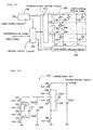
- Fig. 1 is a block diagram showing the configuration of a power-source circuit to which a voltage booster circuit according to the present invention is applied.
- a power-source circuit 100 is formed of a voltage detection circuit 110, a voltage-boost control circuit 120, and a voltage booster circuit 130.
- the voltage detection circuit 110 detects the output voltage Vout of the voltage booster circuit 130 and sends the detection result to the voltage-boost control circuit 120.
- the voltage-boost control circuit 120 generates control signals "a,” "b,” “c1,” “c2,” and "d” used for controlling the voltage-boost magnification of the voltage booster circuit 130 according to the output voltage Vout detected by the voltage detection circuit 110.
- the voltage booster circuit 130 boosts an input voltage Vin between once and four times and outputs the output voltage Vout according to the control signals "a,” “b,” “c1,” “ “c2,” and “d” generated by the voltage-boost control circuit 120.
- the voltage booster circuit 130 is formed of transistors Q2 to Q8 serving as switching devices, auxiliary capacitors C1 (first charge-accumulating device and C2 second charge-accumulating device), and an output capacitor Cout.
- one terminal C1L of the auxiliary capacitor C1 is connected to a ground line (first line) having a reference potential through an n-channel transistor Q4 having the control signal "a" as a gate signal, and is also connected to the supply line (second line) of the input voltage Vin through a p-channel transistor Q3 having the control signal "b" as a gate signal.
- the other terminal C1H of the auxiliary capacitor C1 is connected as described below.
- the terminal C1H is first connected to the supply line of the input voltage Vin through an n-channel transistor Q2 having the control signal "a" as a gate signal; is secondly connected to one terminal C2L of the auxiliary capacitor C2 through a p-channel transistor Q7 having the control signal "d” as a gate signal, and is further connected to the ground line through an n-channel transistor Q8 having the control signal "c2" as a gate signal; and is fourthly connected to the other terminal C2H of the auxiliary capacitor C2 through an n-channel transistor Q6 having the control signal "c1" as a gate signal, and is further connected to the output line of the output voltage Vout through a p-channel transistor Q5 having the control signal "d” as a gate signal.
- the output capacitor Cout is connected in parallel between the output line and the ground line in order to smooth the output voltage Vout.
- the operation of the power-source circuit 100 having the above configuration will be described next.
- the voltage-boost control circuit 120 essentially controls the voltage-boost magnification of the voltage booster circuit 130 in any range according to the output voltage Vout, but for the sake of convenience, the operation of the power-source circuit 100 will be described for each of the cases in which the voltage-boost magnification is set to four, three, two, and one, and then for a case in which the voltage-boost magnification is set to any value.
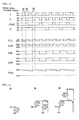
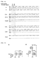
- the voltage-boost control circuit 120 generates control signals "a,” “b,” “c1,” “c2,” and “d” as shown by a timing chart illustrated in Fig. 3.
- the control signal "a” is formed by narrowing the pulse width of the control signal "b.”
- the control signals "c1” and “c2” are formed by inverting the control signal “b” and scaling it down by a factor of 2 (thinning the number of pulse to 1/2).
- the control signal “d” is formed by inverting the control signal "c1” or "c2” and delaying it by half the period.
- the auxiliary capacitor C2 is charged with 2Vin, which is the potential difference between both terminals. After this operation, the transistors Q2 to Q8 are all turned off temporarily.
- the potential of the terminal C2H becomes 4Vin, which is offset from the potential of the terminal C1H (C2L), 2Vin, to a higher potential by the output voltage 2Vin of the auxiliary capacitor C2, and then, it is smoothed by the output capacitor Cout.
- the output voltage Vout is gradually reduced from 4Vin in a period from when the transistor Q5 is turned off to when it is turned on.
- the periods 1 ⁇ , 2 ⁇ , and 3 ⁇ are repeated to boost the input voltage Vin four times and to output it.
- the voltage-boost control circuit 120 generates control signals "a,” “b,” “c1,” “c2,” and “d” shown in a timing chart illustrated in Fig. 5.
- the control signals "a” and “b” are the same as those used in the four-times voltage boost.
- the control signals "c1” and “c2” are the same as the control signal "a,” and, in the same way, the control signal "d” is the same as the control signal "b".
- the transistors Q2, Q4, Q6, and Q8 are turned on whereas the other transistors are all turned off in a period indicated by 1 ⁇ in Fig. 5, namely, in a period when all the control signals "a,” “b,” “c1,” "c2,” and “d” have an "H” level. Therefore, since the auxiliary capacitors C1 and C2 are connected in parallel such that the terminal C1H and the terminal C2H are connected to the supply line of the input voltage Vin and the terminal C1L and the terminal C2L are connected to the ground line, as indicated by 1 ⁇ in Fig. 6, the auxiliary capacitors C1 and C2 are charged with the input voltage Vin. After this operation, the transistors Q2 to Q8 are all turned off temporarily.
- the potential of the terminal C2H becomes 3Vin, which is offset from the potential of the terminal C1H (C2L), 2Vin, to a higher potential by the output voltage Vin of the auxiliary capacitor C2.
- the output voltage Vout is gradually reduced from 3Vin in a period from when the transistor Q5 is turned off to when it is turned on.
- the periods 1 ⁇ and 2 ⁇ are repeated to boost the input voltage Vin three times and to output it.
- the voltage-boost control circuit 120 generates control signals "a,” “b,” “c1,” “c2,” and “d” shown in a timing chart illustrated in Fig. 7.
- the control signals "a” and “b” are the same as those used in the four-times and three-times voltage boosts.
- the control signal “c1” is formed by inverting the control signal "b.”
- the control signal “c2” always has an "L” level.
- the control signal “d” is the same as the control signal "b.”
- the transistors Q2 and Q4 are turned on whereas the other transistors are all turned off in a period indicated by 1 ⁇ in Fig. 7, namely, in a period when the control signals "a,” “b,” and “d” have an "H” level except for the control signal "c1" and "c2", as in the period indicated by 1 ⁇ in the four-times voltage boost. Therefore, as shown in 1 ⁇ in Fig. 8, the auxiliary capacitor C1 is charged with the input voltage Vin. After this operation, the transistors Q2 to Q8 are all turned off temporarily.
- the periods 1 ⁇ and 2 ⁇ are repeated to boost the input voltage Vin twice and to output it.
- the voltage-boost control circuit 120 generates control signals "a,” “b,” “c1,” “c2,” and “d” shown in a timing chart illustrated in Fig. 9.
- the control signal "a” is the same as that used in the four-times, three-times, and two-times voltage boosts.
- the control signal "b” always has an "H” level.
- the control signal "c1” is the same as the control signal "a”.
- the control signal “c2” always has a "L” level.
- the control signal “d” is formed by inverting the control signal "a” or "c1".
- the input voltage Vin is output as is as the output voltage Vout.
- the voltage booster circuit in the present embodiment allows four-times, three-times, two-times, and one-times voltage boosts.
- the magnification is actually allowed to be changed to any value between four and one.
- the voltage-boost control circuit 120 sends control signals for different voltage-boost magnifications in a time-division manner and controls the ratio of the supply periods to allow the voltage-boost magnification to be set to a value between the different magnifications.
- the output voltage Vout which is smoothed by the output capacitor Cout
- the voltage-boost magnification is substantially set to 3.5.
- the control signals for the four-times voltage boost and the control signals for the three-times voltage boost are alternately sent with respective supply-period ratios of 25% and 75%, for example, the voltage-boost magnification is substantially set to 3.25. In either case, since the control signals "a" and "b" are used in common, only the control signal "c1" ("c2") and the control signal "d" need to be changed.
- controlling the supply-period ratio of the control signals means exclusively controlling the connection patterns required to obtain each voltage in a time-division manner.
- a combination of the control signals for the four-times voltage boost and those for the two-times or one-times voltage boost can be used in addition to a combination of the control signals for the four-times voltage boost and those for the three-times voltage boost.
- control signals for the four-times voltage boost and those for the two-times voltage boost need to be alternately sent with the respective supply-period ratios of 75 % and 25%, or the control signals for the four-times voltage boost and those for the one-times voltage boost need to be alternately sent with the respective supply-period ratios of 83.3% and 16.7%.
- a combination of the control signals for the four-times voltage boost and those for the two-times or one-times voltage boost or a combination of the control signals for the three-times voltage boost and those for the one-times voltage boost can be used in addition to a combination of the control signals for the three-times voltage boost and those for the two-times voltage boost.
- a combination of the control signals for the four-times or three-times voltage boost and those for the one-times voltage boost can be used in addition to a combination of the control signals for the two-times voltage boost and those for the once voltage boost.
- Such a control is actually performed in the following way.
- the period when the control signals for a higher-magnification voltage boost are sent is set shorter than the period when the control signals for a lower-magnification voltage boost are sent.
- the period when the control signals for a higher-magnification voltage boost are sent is set longer than the period when the control signals for a lower-magnification voltage boost are sent.
- feedback control is used to make the output voltage Vout constant, in which control signals for each voltage-boost magnification are sent in a time-division manner according to the comparison between the target voltage Vref and the output voltage Vout, and the supply-period ratio is controlled.
- the present invention is not limited to the use of this control.
- the voltage-boost control circuit 120 may be configured such that the output voltage Vout is made constant by feed-forward control in which control signals for each voltage-boost magnification are sent in a time-division manner according to the comparison with the input voltage Vin and the supply-period ratio is controlled.
- FIG. 10 is a circuit diagram showing the configuration of a voltage booster circuit 132 in the present embodiment.
- the voltage booster circuit 132 shown in this figure is used in the power-source circuit 100 instead of the voltage booster circuit 130 shown in Fig. 2.
- the voltage booster circuit 132 is formed by adding auxiliary capacitors C3 and C4 to the voltage booster circuit 130 in the first embodiment. Details will be described next.
- a terminal C2H of an auxiliary circuit C2 is first connected to one terminal C3L of an auxiliary capacitor C3 through a p-channel transistor Q10 having a control signal "f” as a gate signal and is further connected to a ground line through an n-channel transistor Q11 having a control signal "e” as a gate signal; and is secondly connected to the other terminal C3H of the auxiliary capacitor C3 through an n-channel transistor Q9 having the control signal "e” as a gate signal.
- the terminal C3H of the auxiliary capacitor C3 is first connected to one terminal C4L of an auxiliary capacitor C4 through a p-channel transistor Q14 having a control signal "g" as a gate signal and is further connected to the ground line through an n-channel transistor Q15 having a control signal "h2" as a gate signal; and is secondly connected to the other terminal C4H of the auxiliary capacitor C4 through an n-channel transistor Q13 having a control signal "h1" as a gate signal and is further connected to the output line of the output voltage Vout through a p-channel transistor Q12 having the control signal "g” as a gate signal.
- An output capacitor Cout is connected in parallel between the output line and the ground line to smooth the output voltage Vout, in the same way as in the first embodiment.
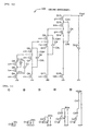
- the voltage-boost control circuit 120 sends control signals in the following periods 1 ⁇ to 5 ⁇ to control switching of each of the transistors Q2 to Q15 in the voltage booster circuit 132.
- the voltage-boost control circuit 120 first connects the terminal C1H to the supply line of the input voltage Vin and also connects the terminal C1L to the ground line as indicated in 1 ⁇ in Fig. 11. With this operation, the auxiliary capacitor C1 is charged with Vin.
- the voltage-boost control circuit 120 connects the terminal C1L to the supply line of the input voltage Vin, the terminal C1H to the terminal C2H, and then the terminal C2L to the ground line as indicated in 2 ⁇ in the figure. With this operation, the potential of the terminal C1H becomes 2Vin, which is offset from the input voltage Vin to a higher potential by the output voltage Vin of the auxiliary capacitor C1, and the auxiliary capacitor C2 is charged with 2Vin.
- the voltage-boost control circuit 120 connects the terminal C1H to the terminal C2L, the terminal C2H to the terminal C3H, and then the terminal C3L to the ground line while the terminal C1L is connected to the supply line of the input voltage Vin, as indicated in 3 ⁇ in the figure.
- the potential of the terminal C2H becomes 4Vin, which is offset from the potential 2Vin of the terminal C1H (C2L) to a higher potential by the output voltage 2Vin of the auxiliary capacitor C2, and the auxiliary capacitor C3 is charged with 4Vin.
- the voltage-boost control circuit 120 connects the terminal C2H to the terminal C3L, the terminal C3H to the terminal C4H, and then the terminal C4L to the ground line while the terminal C1L is connected to the supply line of the input voltage Vin and the terminal C1H is connected to the terminal C2L, as indicated in 4 ⁇ in the figure.
- the potential of the terminal C3H becomes 8Vin, which is offset from the potential 4Vin of the terminal C2H (C3L) to a higher potential by the output voltage 4Vin of the auxiliary capacitor C3, and the auxiliary capacitor C4 is charged with 8Vin.
- the voltage-boost control circuit 120 connects the terminal C3H to the terminal C4L and the terminal C4H to the output line of the output voltage Vout while the terminal C1L is connected to the supply line of the input voltage Vin, the terminal C1H is connected to the terminal C2L, and the terminal C2H is connected to the terminal C3L, as indicated in 5 ⁇ in the figure.
- the potential of the output line becomes 16Vin, which is offset from the potential 8Vin of the terminal C3H (C4L) to a higher potential by the output voltage 8Vin of the auxiliary capacitor C4. In this way, a 16-times voltage boost is performed with the four auxiliary capacitors C1 to C4.
- the auxiliary capacitors C1 to C4 can be charged with the following potentials in the present embodiment.
- the auxiliary capacitor C1 can be charged with Vin
- the auxiliary capacitor C2 can be charged with Vin or 2Vin
- the auxiliary capacitor C3 is charged with Vin, 2Vin, 3Vin, or 4Vin
- the auxiliary capacitor C4 can be charged with 0, Vin, 2Vin, ..., 7Vin, and 8Vin. Therefore, the supply line of the input voltage Vin is offset by the output voltage obtained by appropriately combining the auxiliary capacitors C1 to C4 to allow an output voltage Vout of Vin, 2Vin, 3Vin, ..., or 16Vin to be obtained.
- the voltage-boost control circuit 120 sends control signals specifying each voltage-boost magnification in a time-division manner and controls the supply-period ratio to allow the voltage-boost magnification to be controlled at any value between 16 and one. Furthermore, the voltage-boost control circuit 120 controls the supply-period ratio according to the result of comparison between the output voltage Vout and the target voltage Vref to allow the output voltage Vout to be made constant between 16Vin and Vin.
- the first and second embodiment are extended, namely, auxiliary capacitors are added in the same way, to allow the input voltage Vin to be boosted 32 times, 64 times, ..., and 2 n times.
- auxiliary capacitors are required for a voltage boost, the configuration can be simplified.
- the voltage-boost magnification can be set to any value between 2 n and one, and further, the output voltage Vout can be made constant therebetween.
- auxiliary capacitors are used for charging and offsetting.
- devices are not limited to auxiliary capacitors. Secondary cells, for example, may be used.
- a positive power source in which the input voltage Vin is set to be in a positive side of the reference potential and the offset direction is set to the positive direction.
- the present invention is not limited to this case.
- the present invention can also be applied to a negative power source in which the input voltage is set to be in the negative side of the reference potential and the offset direction is set to the negative direction.
- connections and switching of the auxiliary capacitors are performed by transistors.
- Other various switches such as analog switches and transmission gates may be used.
- the voltage booster circuit 130 in the first embodiment, the voltage booster circuit 132 in the second embodiment, and a voltage booster circuit obtained by extending these voltage booster circuits can be used, for example, as a power-source circuit that sends electrical power to each section of a liquid-crystal display apparatus.
- Fig. 12 is a block diagram showing the electrical configuration of this liquid-crystal display apparatus.
- a liquid-crystal display panel 200 has a liquid-crystal device 202 formed at each intersection of i data lines X1 to Xi and j scanning lines Y1 to Yj.
- Each liquid-crystal device 202 has a configuration in which a liquid-crystal display element (liquid-crystal layer) 204 and a thin-film diode (hereinafter called a TFD) device 206 are connected in series.
- a liquid-crystal display element liquid-crystal layer
- a TFD thin-film diode
- the scanning lines Y1 to Yj are driven by a scanning-signal driving circuit 210, and the data lines X1 to Xi are driven by a data-signal driving circuit 220.
- the scanning-signal driving circuit 210 and the data-signal driving circuit 220 are controlled by a driving control circuit 240.
- the TFD device 206 is connected to a scanning line and the liquid-crystal layer 204 is connected to a data line.
- the configuration may be formed such that the TFD device 206 is connected to a data line and the liquid-crystal layer 204 is connected to a scanning line.
- a power-source circuit 100 controls the voltage-boost magnification of an input voltage Vin to output various output voltages, such as various selection voltages used in the scanning-signal driving circuit 210, data-signal voltages used in the data-signal driving circuit 220, and voltages used in the driving control circuit 240.
- the voltage booster circuit 130 described above, is applied to the power-source circuit 100.
- liquid-crystal display apparatus various types can be employed such as an active-matrix type using thin-film transistors (TFT) and a passive-matrix type not using switching elements such as TFDs and TFTs.
- TFT thin-film transistors
- the voltage booster circuit according to the present invention can also be applied to a power-source circuit of an electroluminescence (EL) display apparatus, in addition to that of the liquid-crystal apparatus, in which row electrodes and column electrodes are formed on an insulating layer covering an EL layer.
- EL electroluminescence
- an electronic unit according to the present invention can be applied not only to display apparatuses but also to projectors, personal computers, pagers, liquid-crystal TV sets, viewfinder-type and monitor-view-type video cassette recorders, car-navigation apparatuses, electronic notebooks, electric calculators, wordprocessors, workstations, cellular phones, videophones, POS terminals, and apparatuses having touch-sensitive panels.
Landscapes
- Engineering & Computer Science (AREA)
- Power Engineering (AREA)
- Dc-Dc Converters (AREA)
- Control Of Indicators Other Than Cathode Ray Tubes (AREA)
- Direct Current Feeding And Distribution (AREA)
- Charge And Discharge Circuits For Batteries Or The Like (AREA)
Claims (11)
- Spannungserhöhungsschaltung, umfassend:wobei diese ersten bis dritten Verbindungsmittel durch eine Spannungserhöhungssteuerschaltung (120) in einer ersten Anordnung steuerbar sind, um eine Spannung zwischen der ersten und zweiten Leitung um einen Vergrößerungsfaktor von 4 zu erhöhen, die Spannungserhöhungsschaltung außerdem mindestens eines umfasst von:erste Verbindungsmittel (Q2, Q4), um eine Anschlussklemme (C1L) eines ersten ladungssammelnden Geräts (C1) mit einer ersten Leitung zu verbinden, die ein vorgegebenes Potential aufweist, und um die andere Anschlussklemme (C1H) des ersten ladungssammelnden Geräts (C1) mit einer zweiten Leitung (Vin) zu verbinden, die ein Potential aufweist, das von dem der ersten Leitung abweicht;zweite Verbindungsmittel (Q3, Q6, Q8), um eine Anschlussklemme (C2L) eines zweiten ladungssammelnden Geräts (C2) mit der ersten Leitung zu verbinden, und um die eine Anschlussklemme (C1L) des ersten ladungssammelnden Geräts (C1) zur zweiten Leitung (Vin) umzuschalten und mit dieser zu verbinden, und um die andere Anschlussklemme (C1H) des ersten ladungssammelnden Geräts (C1L) zur anderen Anschlussklemme (C2H) des zweiten ladungssammelnden Geräts (C2) umzuschalten und mit dieser zu verbinden; unddritte Verbindungsmittel (Q5, Q7), um die eine Anschlussklemme (C2L) des zweiten ladungssammelnden Geräts (C2) zur anderen Anschlussklemme (C1H) des ersten ladungssammelnden Geräts (C1) umzuschalten und mit dieser zu verbinden, um die andere Anschlussklemme (C2H) des zweiten ladungssammelnden Geräts (C2) zu einer Ausgangsleitung umzuschalten und mit dieser zu verbinden, und um die eine Anschlussklemme (C1L) des ersten ladungssammelnden Geräts (C1) zur zweiten Leitung (Vin) umzuschalten und mit dieser zu verbinden,wobei diese ersten, dritten und vierten Verbindungsmittel durch die Spannungserhöhungssteuerschaltung (120) in einer zweiten Anordnung steuerbar sind, um eine Spannung zwischen der ersten und zweiten Leitung um einen Vergrößerungsfaktor von 3 zu erhöhen;vierten Verbindungsmitteln (Q6, Q8), um die eine Anschlussklemme (C2L) des zweiten ladungssammelnden Geräts (C2) mit der ersten Leitung zu verbinden, und um die andere Anschlussklemme (C2H) des zweiten ladungssammelnden Geräts (C2) mit der zweiten Leitung (Vin) zu verbinden,wobei diese ersten und fünften Verbindungsmittel durch die Spannungserhöhungssteuerschaltung (120) in einer dritten Anordnung steuerbar sind, um eine Spannung zwischen der ersten und zweiten Leitung um einen Vergrößerungsfaktor von 2 zu erhöhen; undfünften Verbindungsmitteln (Q3, Q5, Q6), um die andere Anschlussklemme (C1H) des ersten ladungssammelnden Geräts (C1) mit der Ausgangsleitung zu verbinden, während die eine Anschlussklemme (C1L) des ersten ladungssammelnden Geräts mit der zweiten Leitung (Vin) verbunden ist,sechsten Verbindungsmitteln (Q2, Q5, Q6), um die zweite Leitung (Vin) mit der Ausgangsleitung zu verbinden,
wobei diese sechsten Verbindungsmittel durch die Spannungserhöhungssteuerschaltung (120) in einer vierten Anordnung steuerbar sind, um eine Spannung zwischen der ersten und zweiten Leitung um einen Vergrößerungsfaktor von 1 zu erhöhen, und außerdem umfassend:die Spannungserhöhungssteuerschaltung (120) ferner angeordnet ist, um Steuersignale für verschiedene Vergrößerungsfaktoren einer der ersten bis vierten Anordnungen entsprechend auf zeitgeteilte Weise zu senden, wodurch ein Verhältnis von Versorgungsperioden so gesteuert wird, dass der Vergrößerungsfaktor der Spannungserhöhung auf einen Wert zwischen zwei verschiedenen Vergrößerungen eingestellt werden kann. - Spannungserhöhungsschaltung nach Anspruch 1, dadurch gekennzeichnet, dass sie die vierten Verbindungsmittel (Q6, Q8) umfasst; und
wobei die Spannungserhöhungssteuerschaltung angeordnet ist, um zu steuern, ob die Verbindung des zweiten ladungssammelnden Geräts durch die zweiten Verbindungsmittel in der ersten Anordnung oder durch die vierten Verbindungsmittel in der zweiten Anordnung hergestellt wird. - Spannungserhöhungsschaltung nach Anspruch 2, dadurch gekennzeichnet, dass
die Spannungserhöhungssteuerschaltung so steuert, dass die Verbindungsperiode des zweiten ladungssammelnden Geräts, die durch die zweiten Verbindungsmittel in der ersten Anordnung hergestellt wird, länger ist als die Verbindungsperibde des zweiten ladungssammelnden Geräts, die durch die vierten Verbindungsmittel in der zweiten Anordnung hergestellt wird, wenn das Potential der zweiten Leitung oder ein Potential an der Ausgangsleitung Absolutwerte aufweisen, die kleiner sind als ein vorgegebener Wert. - Spannungserhöhungsschaltung nach einem der Ansprüche 2 und 3, dadurch gekennzeichnet, dass sie die fünften Verbindungsmittel (Q3, Q5, Q6) umfasst; und
wobei die Spannungserhöhungssteuerschaltung angeordnet ist, um zu steuern, ob die Verbindung des zweiten ladungssammelnden Geräts durch die zweiten und vierten Verbindungsmittel jeweils in der ersten und zweiten Anordnung hergestellt wird, oder die Verbindung durch die fünften Verbindungsmittel in der dritten Anordnung hergestellt wird. - Spannungserhöhungsschaltung nach Anspruch 4, dadurch gekennzeichnet, dass
die Spannungserhöhungssteuerschaltung so steuert, dass die Verbindungsperiode des zweiten ladungssammelnden Geräts, die durch die zweiten und vierten Verbindungsmittel jeweils in der ersten und zweiten Anordnung hergestellt wird, länger ist als die Verbindungsperiode, die durch die fünften Verbindungsmittel in der dritten Anordnung hergestellt wird, wenn das Potential der zweiten Leitung oder ein Potential an der Ausgangsleitung Absolutwerte aufweisen, die kleiner sind als ein vorgegebener Wert. - Spannungserhöhungsschaltung nach einem der Ansprüche 4 und 5, dadurch gekennzeichnet, dass sie die sechsten Verbindungsmittel (Q2, Q5, Q6) umfasst; und
wobei die Spannungserhöhungssteuerschaltung angeordnet ist, um zu steuern, ob die Verbindung des zweiten ladungssammelnden Geräts durch die zweiten und vierten Verbindungsmittel jeweils in der ersten und zweiten Anordnung hergestellt wird oder die Verbindung durch die fünften Verbindungsmittel in der dritten Anordnung hergestellt wird, oder die Verbindung durch die sechsten Verbindungsmittel in der vierten Anordnung hergestellt wird. - Spannungserhöhungsschaltung nach Anspruch 6, dadurch gekennzeichnet, dass
die Spannungserhöhungssteuerschaltung so steuert, dass die Verbindungsperiode des zweiten ladungssammelnden Geräts, die durch die zweiten und vierten Verbindungsmittel jeweils in der ersten und zweiten Anordnung hergestellt wird, oder die Verbindungsperiode, die durch die fünften Verbindungsmittel in der dritten Anordnung hergestellt wird, länger ist als die Verbindungsperiode, die durch die sechsten Verbindungsmittel in der vierten Anordnung hergestellt wird, wenn das Potential der zweiten Leitung oder ein Potential an der Ausgangsleitung Absolutwerte aufweisen, die kleiner sind als ein vorgegebener Wert. - Spannungserhöhungsschaltung nach einem der obigen Ansprüche, wobei diese Schaltung n ladungssammelnde Geräte umfasst, wodurch der Vergrößerungsfaktor der Spannungserhöhung auf jeden Wert zwischen 1 und 2n eingestellt werden kann.
- Spannungserhöhungsverfahren, umfassend:wobei diese ersten bis dritten Schritte in einer ersten Anordnung steuerbar sind, um eine Spannung zwischen der ersten und zweiten Leitung um einen Vergrößerungsfaktor von 4 zu erhöhen, das Verfahren außerdem dadurch gekennzeichnet ist, dass es mindestens eines umfasst von:einen ersten Schritt des Verbindens einer Anschlussklemme (C1L) eines ersten ladungssammelnden Geräts (C1) mit einer ersten Leitung, die ein vorgegebenes Potential aufweist, und des Verbindens der anderen Anschlussklemme (C1H) des ersten ladungssammelnden Geräts (C1) mit einer zweiten Leitung (Vin), die ein Potential aufweist, das von dem der ersten Leitung abweicht;einen zweiten Schritt des Verbindens einer Anschlussklemme (C2L) eines zweiten ladungssammelnden Geräts (C2) mit der ersten Leitung, und des Umschaltens und Verbindens der einen Anschlussklemme (C1L) des ersten ladungssammelnden Geräts (C1) mit der zweiten Leitung (Vin) und des Umschaltens und Verbindens der anderen Anschlussklemme (C1H) des ersten ladungssammelnden Geräts (C1) mit der anderen Anschlussklemme (C2H) des zweiten ladungssammelnden Geräts (C2); undeinen dritten Schritt des Umschaltens und Verbindens der einen Anschlussklemme (C2L) des zweiten ladungssammelnden Geräts (C2) mit der anderen Anschlussklemme (C1H) des ersten ladungssammelnden Geräts (C1) und des Umschaltens und Verbindens der anderen Anschlussklemme (C2H) des zweiten ladungssammelnden Geräts (C2) mit einer Ausgangsleitung,wobei diese ersten, dritten und vierten Schritte in einer zweiten Anordnung steuerbar sind, um eine Spannung zwischen der ersten und zweiten Leitung um einen Vergrößerungsfaktor von 3 zu erhöhen;einem vierten Schritt des Verbindens der einen Anschlussklemme (C2L) des zweiten ladungssammelnden Geräts (C2) mit der ersten Leitung, und zum Verbinden der anderen Anschlussklemme (C2H) des zweiten ladungssammelnden Geräts (C2) mit der zweiten Leitung (Vin),wobei diese ersten und fünften Schritte in einer dritten Anordnung steuerbar sind, um eine Spannung zwischen der ersten und zweiten Leitung um einen Vergrößerungsfaktor von 2 zu erhöhen; undeinen fünften Schritt des Verbindens der anderen Anschlussklemme (C1H) des ersten ladungssammelnden Geräts (C1) mit der Ausgangsleitung, während die eine Anschlussklemme (C1L) des ersten ladungssammelnden Geräts mit der zweiten Leitung (Vin) verbunden ist,wobei dieses sechste Verbindungsmittel in einer vierten Anordnung steuerbar ist, um eine Spannung zwischen der ersten und zweiten Leitung um einen Vergrößerungsfaktor von 1 zu erhöhen; undeinen sechsten Schritt des Verbindens der zweiten Leitung (Vin) mit der Ausgangsleitung,das Senden von Steuersignalen für verschiedene Vergrößerungsfaktoren einer der ersten bis vierten Anordnungen entsprechend auf zeitgeteilte Weise, wodurch ein Verhältnis von Versorgungsperioden so gesteuert wird, dass der Vergrößerungsfaktor der Spannungserhöhung auf einen Wert zwischen zwei verschiedenen Vergrößerungen eingestellt werden kann.
- Verfahren nach Anspruch 9, umfassend die Schritte des Verbindens von n ladungssammelnden Geräten, wodurch der Vergrößerungsfaktor der Spannungserhöhung auf jeden Wert zwischen 1 und 2n eingestellt werden kann.
- Elektronisches Gerät, umfassend:wobei ein Potential an der Ausgangsleitung als eine Stromquelle verwendet wird.eine Spannungserhöhungsschaltung nach einem der Ansprüche 1 bis 8,
Applications Claiming Priority (2)
| Application Number | Priority Date | Filing Date | Title |
|---|---|---|---|
| JP06521799A JP3316468B2 (ja) | 1999-03-11 | 1999-03-11 | 昇圧回路、昇圧方法および電子機器 |
| JP6521799 | 1999-03-11 |
Publications (3)
| Publication Number | Publication Date |
|---|---|
| EP1037367A2 EP1037367A2 (de) | 2000-09-20 |
| EP1037367A3 EP1037367A3 (de) | 2000-11-02 |
| EP1037367B1 true EP1037367B1 (de) | 2005-11-09 |
Family
ID=13280537
Family Applications (1)
| Application Number | Title | Priority Date | Filing Date |
|---|---|---|---|
| EP00301991A Expired - Lifetime EP1037367B1 (de) | 1999-03-11 | 2000-03-10 | Spannungserhöhungsschaltung, Spannungserhöhungsverfahren, und elektronisches Gerät |
Country Status (7)
| Country | Link |
|---|---|
| US (1) | US6556064B1 (de) |
| EP (1) | EP1037367B1 (de) |
| JP (1) | JP3316468B2 (de) |
| KR (1) | KR100615837B1 (de) |
| CN (1) | CN1267120A (de) |
| DE (1) | DE60023775T2 (de) |
| TW (1) | TW527500B (de) |
Families Citing this family (27)
| Publication number | Priority date | Publication date | Assignee | Title |
|---|---|---|---|---|
| DE10050496B4 (de) | 2000-10-11 | 2015-04-02 | Texas Instruments Deutschland Gmbh | Gleichspannungswandler |
| JP2004064937A (ja) * | 2002-07-31 | 2004-02-26 | Nec Corp | チャージポンプ型昇圧回路 |
| EP1537645A1 (de) * | 2002-08-28 | 2005-06-08 | Koninklijke Philips Electronics N.V. | Spannungsverdopplerschaltung |
| US6861894B2 (en) * | 2002-09-27 | 2005-03-01 | Sandisk Corporation | Charge pump with Fibonacci number multiplication |
| US6985024B2 (en) * | 2003-08-21 | 2006-01-10 | Analog Devices, Inc. | Voltage multiplier |
| JP3846478B2 (ja) | 2004-01-15 | 2006-11-15 | セイコーエプソン株式会社 | 昇圧回路、電源回路及び液晶駆動装置 |
| JP3841083B2 (ja) * | 2004-01-20 | 2006-11-01 | セイコーエプソン株式会社 | 昇圧回路、電源回路及び液晶駆動装置 |
| JP4352937B2 (ja) * | 2004-03-03 | 2009-10-28 | セイコーエプソン株式会社 | 電源回路、電気光学装置および電子機器 |
| JP2004248497A (ja) * | 2004-03-08 | 2004-09-02 | Seiko Epson Corp | 電源回路、液晶装置及び電子機器 |
| JP3904579B2 (ja) | 2004-12-03 | 2007-04-11 | ローム株式会社 | 電源装置およびそれを用いた発光装置、電子機器 |
| JP4024814B2 (ja) * | 2005-02-24 | 2007-12-19 | シャープ株式会社 | チャージポンプ方式dc/dcコンバータ回路 |
| US20060250177A1 (en) * | 2005-05-09 | 2006-11-09 | Thorp Tyler J | Methods and apparatus for dynamically reconfiguring a charge pump during output transients |
| US7236046B2 (en) * | 2005-11-01 | 2007-06-26 | Catalyst Semiconductor, Inc. | LED bias current control using adaptive fractional charge pump |
| US7557641B2 (en) * | 2005-11-01 | 2009-07-07 | Catalyst Semiconductor, Inc. | Fractional charge pump for step-down DC-DC converter |
| US7602232B2 (en) * | 2005-11-01 | 2009-10-13 | Semiconductor Components Industries, L.L.C. | Programmable fractional charge pump for DC-DC converter |
| JP2007259519A (ja) * | 2006-03-20 | 2007-10-04 | Rohm Co Ltd | チャージポンプ回路、lcdドライバic、液晶表示装置 |
| JP2008125145A (ja) * | 2006-11-08 | 2008-05-29 | Mcm Japan Kk | 昇圧回路及び降圧回路 |
| JP2008125269A (ja) * | 2006-11-14 | 2008-05-29 | Mcm Japan Kk | 昇圧回路及び降圧回路 |
| DE102006060011A1 (de) * | 2006-12-19 | 2008-07-03 | Austriamicrosystems Ag | Spannungskonverter und Verfahren zur Spannungskonversion |
| US8068356B2 (en) * | 2008-05-28 | 2011-11-29 | Taiwan Semiconductor Manufacturing Co., Ltd. | Low power one-shot boost circuit |
| JP5600881B2 (ja) * | 2009-03-06 | 2014-10-08 | セイコーエプソン株式会社 | Dc−dcコンバータ回路、電気光学装置及び電子機器 |
| JP2011083141A (ja) * | 2009-10-08 | 2011-04-21 | Renesas Electronics Corp | 昇圧電源回路 |
| KR101315143B1 (ko) * | 2012-08-22 | 2013-10-14 | 전북대학교산학협력단 | 높은 승압 비를 갖는 고효율 dc/dc 컨버터 |
| US8693224B1 (en) * | 2012-11-26 | 2014-04-08 | Arctic Sand Technologies Inc. | Pump capacitor configuration for switched capacitor circuits |
| JP5995940B2 (ja) * | 2014-11-13 | 2016-09-21 | ラピスセミコンダクタ株式会社 | 昇圧方法 |
| US10396776B2 (en) | 2017-06-29 | 2019-08-27 | Apple Inc. | Drive voltage booster |
| KR102695525B1 (ko) * | 2019-05-30 | 2024-08-14 | 삼성전자주식회사 | 부스트 컨버터 및 부스트 컨버터에 적용되는 셀 |
Family Cites Families (16)
| Publication number | Priority date | Publication date | Assignee | Title |
|---|---|---|---|---|
| GB1364618A (en) | 1971-12-03 | 1974-08-21 | Seiko Instr & Electronics | Voltage boosters |
| JPS62277066A (ja) * | 1986-05-23 | 1987-12-01 | Nec Corp | 倍電圧器 |
| US4797899A (en) | 1986-12-15 | 1989-01-10 | Maxim Integrated Products, Inc. | Integrated dual charge pump power supply including power down feature and rs-232 transmitter/receiver |
| US5051882A (en) | 1989-01-27 | 1991-09-24 | Teledyne Industries | Three reservoir capacitor charge pump circuit |
| GB2245112A (en) * | 1990-06-13 | 1991-12-18 | Philips Electronic Associated | Dc/dc voltage multiplier. |
| JP2963914B2 (ja) | 1990-08-05 | 1999-10-18 | 新日本無線株式会社 | 昇圧回路 |
| DE69205885T2 (de) * | 1991-05-15 | 1996-06-13 | Matsushita Electric Works Ltd | Apparat für den Betrieb von Entladungslampen. |
| JPH06327236A (ja) | 1991-11-01 | 1994-11-25 | Seiko Epson Corp | 昇圧方法 |
| JPH05268763A (ja) | 1992-03-17 | 1993-10-15 | Nec Corp | Dc/dcコンバータ回路およびそれを用いたrs−232インタフェース回路 |
| JPH05336734A (ja) * | 1992-03-30 | 1993-12-17 | Sumitomo Metal Ind Ltd | Dc−dcコンバータ |
| JPH0828965B2 (ja) * | 1992-09-02 | 1996-03-21 | 日本電気株式会社 | 電圧変換回路 |
| US5606491A (en) * | 1995-06-05 | 1997-02-25 | Analog Devices, Inc. | Multiplying and inverting charge pump |
| JPH09312968A (ja) | 1996-05-22 | 1997-12-02 | Nec Corp | チャージポンプ回路 |
| US5668710A (en) * | 1996-07-03 | 1997-09-16 | Telcom Semiconductor, Inc. | Charge pump circuit having independent inverted and non-inverted terminals |
| JP2000047624A (ja) * | 1998-07-27 | 2000-02-18 | Denso Corp | 表示装置用駆動回路 |
| JP2000262044A (ja) * | 1999-03-09 | 2000-09-22 | Mitsubishi Electric Corp | 半導体集積回路装置 |
-
1999
- 1999-03-11 JP JP06521799A patent/JP3316468B2/ja not_active Expired - Lifetime
-
2000
- 2000-03-03 TW TW089103831A patent/TW527500B/zh not_active IP Right Cessation
- 2000-03-08 US US09/520,787 patent/US6556064B1/en not_active Expired - Lifetime
- 2000-03-09 CN CN00103768A patent/CN1267120A/zh active Pending
- 2000-03-10 EP EP00301991A patent/EP1037367B1/de not_active Expired - Lifetime
- 2000-03-10 KR KR1020000011995A patent/KR100615837B1/ko not_active Expired - Lifetime
- 2000-03-10 DE DE60023775T patent/DE60023775T2/de not_active Expired - Lifetime
Also Published As
| Publication number | Publication date |
|---|---|
| JP3316468B2 (ja) | 2002-08-19 |
| DE60023775T2 (de) | 2006-06-29 |
| EP1037367A3 (de) | 2000-11-02 |
| JP2000262045A (ja) | 2000-09-22 |
| DE60023775D1 (de) | 2005-12-15 |
| TW527500B (en) | 2003-04-11 |
| KR100615837B1 (ko) | 2006-08-25 |
| EP1037367A2 (de) | 2000-09-20 |
| US6556064B1 (en) | 2003-04-29 |
| CN1267120A (zh) | 2000-09-20 |
| KR20010014560A (ko) | 2001-02-26 |
Similar Documents
| Publication | Publication Date | Title |
|---|---|---|
| US6556064B1 (en) | Voltage boosting circuit and method | |
| US6960955B2 (en) | Charge pump-type booster circuit | |
| US7541859B2 (en) | Charge pump circuit | |
| US7072193B2 (en) | Integrated charge pump DC/DC conversion circuits using thin film transistors | |
| US6445623B1 (en) | Charge pumps with current sources for regulation | |
| EP2095494B1 (de) | Ladungspumpenschaltung und betriebsverfahren dafür | |
| US9899918B2 (en) | DC/DC converter, driving method thereof, and power supply using the same | |
| US7737767B2 (en) | Control circuit and control method for charge pump circuit | |
| US8183844B2 (en) | Switching power source | |
| WO2006043479A1 (ja) | スイッチング電源装置およびそれを用いた電子機器 | |
| US6753623B2 (en) | Switched capacitor array circuits having universal rest state and method | |
| US6650100B1 (en) | Bootstrap technique for a multiple mode switching regulator | |
| US8143938B2 (en) | Boost circuit and liquid crystal display device using boost circuit | |
| US20100176872A1 (en) | Charge Pump Circuit, LCD Driver IC, And Electronic Appliance | |
| CN1881760B (zh) | 用来提供电源的设备 | |
| US7088356B2 (en) | Power source circuit | |
| US10152937B2 (en) | Semiconductor device, power supply circuit, and liquid crystal display device | |
| US8379009B2 (en) | Booster power supply circuit that boosts input voltage | |
| US7884497B2 (en) | Power supply circuit | |
| JP3702741B2 (ja) | 電源回路および液晶表示装置 | |
| CN116909341B (zh) | 低压降调节器电路、对应的设备和方法 | |
| JP2004343893A (ja) | 昇圧回路 | |
| US8350840B2 (en) | Switching circuit, DC-DC converter and display driver integrated circuit including the same | |
| US12567804B2 (en) | Switching scheme for operating a three-level buck converter in a two-level buck converter mode | |
| TWI834449B (zh) | 用於切換式轉換器之電源供應電路 |
Legal Events
| Date | Code | Title | Description |
|---|---|---|---|
| PUAI | Public reference made under article 153(3) epc to a published international application that has entered the european phase |
Free format text: ORIGINAL CODE: 0009012 |
|
| PUAL | Search report despatched |
Free format text: ORIGINAL CODE: 0009013 |
|
| AK | Designated contracting states |
Kind code of ref document: A2 Designated state(s): DE FR GB |
|
| AX | Request for extension of the european patent |
Free format text: AL;LT;LV;MK;RO;SI |
|
| AK | Designated contracting states |
Kind code of ref document: A3 Designated state(s): AT BE CH CY DE DK ES FI FR GB GR IE IT LI LU MC NL PT SE |
|
| AX | Request for extension of the european patent |
Free format text: AL;LT;LV;MK;RO;SI |
|
| 17P | Request for examination filed |
Effective date: 20010430 |
|
| AKX | Designation fees paid |
Free format text: DE FR GB |
|
| 17Q | First examination report despatched |
Effective date: 20040809 |
|
| GRAP | Despatch of communication of intention to grant a patent |
Free format text: ORIGINAL CODE: EPIDOSNIGR1 |
|
| GRAS | Grant fee paid |
Free format text: ORIGINAL CODE: EPIDOSNIGR3 |
|
| GRAA | (expected) grant |
Free format text: ORIGINAL CODE: 0009210 |
|
| AK | Designated contracting states |
Kind code of ref document: B1 Designated state(s): DE FR GB |
|
| REG | Reference to a national code |
Ref country code: GB Ref legal event code: FG4D |
|
| REF | Corresponds to: |
Ref document number: 60023775 Country of ref document: DE Date of ref document: 20051215 Kind code of ref document: P |
|
| ET | Fr: translation filed | ||
| PLBE | No opposition filed within time limit |
Free format text: ORIGINAL CODE: 0009261 |
|
| STAA | Information on the status of an ep patent application or granted ep patent |
Free format text: STATUS: NO OPPOSITION FILED WITHIN TIME LIMIT |
|
| 26N | No opposition filed |
Effective date: 20060810 |
|
| REG | Reference to a national code |
Ref country code: FR Ref legal event code: PLFP Year of fee payment: 16 |
|
| PGFP | Annual fee paid to national office [announced via postgrant information from national office to epo] |
Ref country code: DE Payment date: 20150305 Year of fee payment: 16 |
|
| PGFP | Annual fee paid to national office [announced via postgrant information from national office to epo] |
Ref country code: FR Payment date: 20150309 Year of fee payment: 16 Ref country code: GB Payment date: 20150304 Year of fee payment: 16 |
|
| REG | Reference to a national code |
Ref country code: DE Ref legal event code: R119 Ref document number: 60023775 Country of ref document: DE |
|
| GBPC | Gb: european patent ceased through non-payment of renewal fee |
Effective date: 20160310 |
|
| REG | Reference to a national code |
Ref country code: FR Ref legal event code: ST Effective date: 20161130 |
|
| PG25 | Lapsed in a contracting state [announced via postgrant information from national office to epo] |
Ref country code: DE Free format text: LAPSE BECAUSE OF NON-PAYMENT OF DUE FEES Effective date: 20161001 Ref country code: FR Free format text: LAPSE BECAUSE OF NON-PAYMENT OF DUE FEES Effective date: 20160331 Ref country code: GB Free format text: LAPSE BECAUSE OF NON-PAYMENT OF DUE FEES Effective date: 20160310 |