EP1038820A2 - Aufrollhaspel - Google Patents
Aufrollhaspel Download PDFInfo
- Publication number
- EP1038820A2 EP1038820A2 EP00106575A EP00106575A EP1038820A2 EP 1038820 A2 EP1038820 A2 EP 1038820A2 EP 00106575 A EP00106575 A EP 00106575A EP 00106575 A EP00106575 A EP 00106575A EP 1038820 A2 EP1038820 A2 EP 1038820A2
- Authority
- EP
- European Patent Office
- Prior art keywords
- reel
- winding drum
- wheels
- reel according
- drum
- Prior art date
- Legal status (The legal status is an assumption and is not a legal conclusion. Google has not performed a legal analysis and makes no representation as to the accuracy of the status listed.)
- Withdrawn
Links
Images

Classifications
-
- B—PERFORMING OPERATIONS; TRANSPORTING
- B65—CONVEYING; PACKING; STORING; HANDLING THIN OR FILAMENTARY MATERIAL
- B65H—HANDLING THIN OR FILAMENTARY MATERIAL, e.g. SHEETS, WEBS, CABLES
- B65H75/00—Storing webs, tapes, or filamentary material, e.g. on reels
- B65H75/02—Cores, formers, supports, or holders for coiled, wound, or folded material, e.g. reels, spindles, bobbins, cop tubes, cans, mandrels or chucks
- B65H75/04—Kinds or types
- B65H75/08—Kinds or types of circular or polygonal cross-section
- B65H75/14—Kinds or types of circular or polygonal cross-section with two end flanges
- B65H75/145—Reinforcement or protection arrangements for the peripheral edge of the flanges
-
- B—PERFORMING OPERATIONS; TRANSPORTING
- B65—CONVEYING; PACKING; STORING; HANDLING THIN OR FILAMENTARY MATERIAL
- B65H—HANDLING THIN OR FILAMENTARY MATERIAL, e.g. SHEETS, WEBS, CABLES
- B65H49/00—Unwinding or paying-out filamentary material; Supporting, storing or transporting packages from which filamentary material is to be withdrawn or paid-out
- B65H49/38—Skips, cages, racks, or containers, adapted solely for the transport or storage of bobbins, cops, or the like
-
- B—PERFORMING OPERATIONS; TRANSPORTING
- B65—CONVEYING; PACKING; STORING; HANDLING THIN OR FILAMENTARY MATERIAL
- B65H—HANDLING THIN OR FILAMENTARY MATERIAL, e.g. SHEETS, WEBS, CABLES
- B65H75/00—Storing webs, tapes, or filamentary material, e.g. on reels
- B65H75/02—Cores, formers, supports, or holders for coiled, wound, or folded material, e.g. reels, spindles, bobbins, cop tubes, cans, mandrels or chucks
- B65H75/34—Cores, formers, supports, or holders for coiled, wound, or folded material, e.g. reels, spindles, bobbins, cop tubes, cans, mandrels or chucks specially adapted or mounted for storing and repeatedly paying-out and re-storing lengths of material provided for particular purposes, e.g. anchored hoses, power cables
- B65H75/38—Cores, formers, supports, or holders for coiled, wound, or folded material, e.g. reels, spindles, bobbins, cop tubes, cans, mandrels or chucks specially adapted or mounted for storing and repeatedly paying-out and re-storing lengths of material provided for particular purposes, e.g. anchored hoses, power cables involving the use of a core or former internal to, and supporting, a stored package of material
- B65H75/40—Cores, formers, supports, or holders for coiled, wound, or folded material, e.g. reels, spindles, bobbins, cop tubes, cans, mandrels or chucks specially adapted or mounted for storing and repeatedly paying-out and re-storing lengths of material provided for particular purposes, e.g. anchored hoses, power cables involving the use of a core or former internal to, and supporting, a stored package of material mobile or transportable
Definitions
- the present invention relates to a reel with a rotatable winding drum, one Holding device in which the winding drum is rotatably mounted and a drive mechanism for rotating the winding drum in the holding device.
- the reel of the present The invention is particularly suitable for rolling up long, heavy, flexible objects.
- reels for rolling up garden hoses or power cables have the advantage that they can be used during the Aufrollvorgangs can lead to the object to be rolled up, but are in terms of their Size and weight limited in that they are still worn by the user can.
- Such reels are therefore not very suitable for rolling up objects large dimensions.
- Examples of reels for objects of very large dimensions are Drums for rolling out telephone or power lines or the like, which if they over or to be laid underground, on special vehicles or other moving vehicles or immovable holding devices must be transported. In the latter case however, the cables in factories wound up stationary on machines on large drums, and the Drums later mounted on chassis are only used for unwinding, but not for winding long, flexible objects.
- the object of the present invention is to provide a To create a reel without additional tools, such as vehicles or trolleys gentle rolling up of the corresponding objects facilitated.
- the holding device of the reel of the present Invention is designed in the form of two wheels, between which the winding drum extends, which in turn is rotatable relative to the wheels via a drive mechanism.
- the advantages of the present invention are that the reel is independent of the Movement of the winding drum can be rolled towards the object to be rolled up, whereby for the user the expenditure of force when winding is less than with a rolling process in which the object to be rolled is pulled towards the reel and that the object to be rolled up in that it does not cross the surface must be pulled, is not easily damaged.
- Another advantage of the present invention is that a rolled object due to the free rollability of the reel can be unrolled by a single person so that it in its full length comes to rest on the ground.
- the roll axis is the reel and the Winding axis arranged in parallel. This allows the reel to be rolled up during or Unrolling the object to be rolled up or unrolled only moves towards or away from it become. A sideways movement of the reel in the direction of the longitudinal axis of the The winding drum is thus excluded. This makes it possible to reel the present invention also easily on a sloping surface in one direction across to use on slopes without the reel perpendicular to the winding direction can break out.
- Another embodiment of the invention has two essentially circular disk-shaped Areas and / or rims on opposite sides with one end of each Winding drum are connected so that the winding drum rotated freely between these areas can be.
- These two essentially circular disk-shaped areas or rims are part the holding device for the winding drum and also serve to ensure that the entire reel can then be unrolled freely, bringing together two functional components of the reel were.
- Material and weight savings achieved As a result, compared to conventional movable reels Material and weight savings achieved.
- the Tires of the holding device can be tubes filled with compressed air or solid material tires be made of suitable elastomeric materials.
- tires for the reel Hoses used so these are preferably provided with valves through which the hoses with Compressed air can be filled.
- the advantage of tires on the reel lies in on the one hand a Schulz of the wheels from damage from the surface on which the reel unrolled, and on the other hand it guarantees a light, damped unrolling.
- Farther Tires made of an elastomeric material ensure good grip of the reel on a smooth surface, which prevents the reel, especially when in use across slopes, slid sideways.
- the wheels have grooves provided rollers or slide bearings by which the winding drum is held freely rotatable.
- the winding drum consists essentially of a cylindrical tube which is attached to opposite ends has disc-shaped devices, the circumferential edge is each stored in the grooves of the rollers or plain bearings of the wheels.
- the circular discs also have spokes or recesses, creating a Weight reduction and reduced material consumption is achieved.
- the wheels and the device for connecting the winding drum to the wheels Have openings that make the cavity in the winding drum accessible from the outside.
- this storage space can e.g. Parts related to the object to be wound used, or tools are housed.
- the opening of the storage space can Protection against falling out objects inside with a cover or a lockable flap.
- the opening to the cavity in the Winding drum on the end of the winding drum facing away from the drive device arranged, and the side of the cavity facing the drive device is defined by an in limited to the cavity arranged partition. The partition is intended to prevent Objects located in the cavity come into contact with the drive device and damage them or be damaged yourself.
- the winding drum is preferably provided with guiding devices which are to be wound up Guide the object in one direction to the center of the winding drum and at the same time from the Keep the reel wheels away to avoid that the object between Winding drum and wheels get damaged and damaged.
- These guide devices extend preferred from the optionally provided with circumferential rim of the wheels to to the circumference of the winding drum, wherein it preferably essentially has the shape of a blunt Have cones, the narrower upper opening ends with the drum circumference.
- the winding drum can pass through a drive device can be rotated.
- the drive device consists of a Hand crank, which, depending on the application, can also be replaced by an electric or internal combustion engine can be, a shaft that extends from the hand crank through the holding pre-weight and on the side of the winding drum fixedly or positively with a transfer gear or directly is connected to the winding drum.
- a transfer gear or directly is connected to the winding drum.
- the one driven by the shaft of the drive device Transmission gear engages in a gear or an internally toothed ring gear on the Winding drum, which rotates it regardless of the movement of the reel wheels can be.
- the reel has a braking or Locking device on the movement of the winding drum relative to the wheels of the Reel slows down or is completely prevented.
- This arrangement means that it does not become one uncontrolled unwinding of the wound object comes if it already is completely wound up and the reel is moved to another location by rolling.
- the reel winding drum can also be offset eccentrically relative to the reel wheels.
- the center of gravity of the reel becomes the one running through the two wheels Central axis removed, and the reel will go to a state where the central axis of the The winding drum comes to lie vertically below the axis through the two wheels.
- This Shifting the center of gravity of the reel means that the reel does not work on slopes starts rolling independently when the free movement of the winding drum relative to the Wheels is locked.
- the gear between the winding drum and the holding device has a, preferably switchable, ratchet mechanism. This works in one Direction like a locking device, but allows free rotation in the opposite direction.
- the reel has another preferred one Embodiment of the invention on a transport lock.
- preference is given to the Wheels of the reel attached, foldable stilts / legs used in the unsecured Condition on the wheels of the reel and secure in the direction of the ground folded and locked.
- the stilts / legs of the transport lock can also be removed be and to secure the reel on appropriate devices on the wheels of the Reel to be attached.
- the transport lock is particularly useful when the Roll-up reel is transported on the loading area of a corresponding transport vehicle. she prevents the reel on the transport vehicle from moving in an uncontrolled manner and Damage caused or suffered.
- these are cylindrical Pipe and the guide device of the winding drum, as well as the circular disc-shaped areas or rims of the wheels and / or the connecting device for storing the winding drum in the wheels made of aluminum or plastic. This ensures high stability and a ensures relatively low weight of the reel.
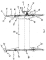
- FIG. 1 shows a cross-sectional view of a reel of the present invention with a substantially cylindrically shaped winding drum 10 which over substantially circular disk-shaped connecting devices 17, 17 'which at the ends of the cylindrical Winding drum 10 are arranged, is mounted in grooves 16 of rollers 15, which in turn is free rotatable with the substantially circular disc-shaped sections 11, 11 'of the wheels of the reel are connected.
- the circular disk-shaped section 11 'shown on the left in FIG Holding device and the circular disk-shaped connecting device connected thereto via rollers 17 'of the winding drum 10 have circular disk-shaped openings 18 in the middle, which make the cavity in the cylindrical winding drum 10 accessible, making this as Storage space can be used around the circumference of the circular disc-shaped sections 11, 11 'of the wheels extend devices 12, 12 'in which tubular tires 13, 13' with circular cross section and valves 14, 14 'are arranged.
- the winding drum 10 has Guide devices 22, 22 ', which have essentially the shape of a blunt cone, and from the circumference of the winding drum 10 to the vicinity of the tires 13, 13 'and the Fastening devices 12, 12 'of the tires extend.
- the reel has from Figure 1 a drive device 20 with a hand crank 21, a shaft connected thereto 24 and a gear 23 connected to the shaft.
- the shaft 24 is in a bearing herein 25 arranged, which via a mounting plate 26 with the substantially circular disk-shaped section 11 of the holding device is connected.
- the winding drum 10 has an internally toothed ring gear 24 which engages in the toothing of the gear 23. As a result, the winding drum 10 can be turned by rotating the shaft 24 using the hand crank 21 can be rotated independently of the reel wheels.
- the embodiment of the shown in Figure 1 and in sections in Figures 2, 3 and 4 With a correspondingly large construction for winding, e.g. a hot air balloon suitable, the process of winding from the upper end of the balloon envelope in the direction of bottom opening of the shell is to take place.
- the reel of the present invention provides the advantage that the hot air balloon can be rolled up and stowed by a single person. Residual air remaining in the balloon envelope is pressed out by the roll-up process.
- the fact that the reel during the reeling process regardless of the movement of the The drum does not have to be rolled against the balloon envelope to be rolled up are pulled over the surface, which on the one hand prevents the casing can be damaged and on the other hand the process with relatively little effort to cope with.
- the object to be rolled up such as the balloon envelope mentioned, is on the Take-up reel wound up, so the entire take-up reel can easily become a corresponding one Transport vehicle or rolled into a storage room.
- the object to be wound up including the reel on a transport vehicle spent, this is even with large, heavy objects and a relative high weight of the reel to be handled by a single person.
- the attached distal end of the object to be wound on the transport vehicle Alone through the winding process, the reel can reach the end of the object to be wound rolled onto the loading surface of the transport vehicle become.
- the drive device of the reel is intended to have a transmission gear provided that this operation can be carried out by a single person.
- the present invention thus provides considerable ease in stowing away objects that can be rolled up and has the advantage that even when stowing large items bulky items can be handled by a single person.
Landscapes
- Storing, Repeated Paying-Out, And Re-Storing Of Elongated Articles (AREA)
- Storage Of Web-Like Or Filamentary Materials (AREA)
Abstract
Description
- Figur 1
- zeigt einen schematischen Querschnitt einer bevorzugten Ausführungsform der vorliegenden Erfindung in Richtung der Längsachse der Wickeltrommel.
- Figur 2
- zeigt eine Vergrößerung des in Figur 1 mit X bezeichneten Kreisausschnittes.
- Figur 3
- zeigt eine Vergrößerung des in Figur 1 mit Y bezeichneten Kreisausschnittes.
- Figur 4
- zeigt eine Vergrößerung des in Figur 1 mit Z bezeichneten Kreisausschnittes.
Claims (21)
- Haspel mit einer drehbaren Wickeltrommel (10), einer Haltevorrichtung, in der die Wickeltrommel (10) drehbar gelagert ist, und einem Antriebsmechanismus (20) zum Rotieren der Wickeltrommel (10) in der Haltevorrichtung, dadurch gekennzeichnet, daß die Haltevorrichtung in Form zweier Räder ausgebildet ist, zwischen denen sich die Wickeltrommel (10) erstreckt, die ihrerseits über einen Antriebsmechanismus relativ zu den Rädern drehbar ist.
- Haspel nach Anspruch 1, dadurch gekennzeichnet, daß die Räder der Haspel (10) im wesentlichen zwei kreisscheibenförmige Teile oder Feigen (11, 11') sind, die auf gegenüberliegenden Seiten mit jeweils einem Ende der Wickeltrommel (10) so verbunden sind, daß die Wickeltrommel (10) frei zwischen diesen Bereichen oder Felgen gedreht werden kann, und auf denen die Haspel frei abgerollt werden kann.
- Haspel nach Anspruch 2, dadurch gekennzeichnet, daß die Räder der Haspel Vorrichtungen (12, 12') zum Halten, Sichern und/oder Befestigen von Bereifungen oder Schläuchen (13, 13') aufweisen.
- Haspel nach einem der Ansprüche 2 oder 3, dadurch gekennzeichnet, daß sich entlang der Umfänge der Räder Bereifungen (13, 13') erstrecken.
- Haspel nach Anspruch 4, dadurch gekennzeichnet, daß die Bereifungen (13, 13') Schläuche sind, die wahlweise aus einem Elastomer bestehen und/oder mit Druckluft gefüllt sind, oder Vollmaterlalreifen sind, die ohne Hohlraum gänzlich aus einem oder verschiedenen Elastomeren bestehen.
- Haspel nach Anspruch 5, dadurch gekennzeichnet, daß die als Schläuche ausgebildeten Bereifungen (13, 13') Ventile (14, 14') zum Befüllen mit Luft aufweisen.
- Haspel nach einem der Ansprüche 1 bis 6, dadurch gekennzeichnet, daß die Räder der Haspel Rollen oder Gleitlager (15) aufweist, die vorzugsweise mit Nuten (16) zur Aufnahme der Wickeltrommel (10) versehen sind, durch die die Wickeltrommel (10) gehalten wird und gleichzeitig relativ zu den Rädern frei drehbar ist.
- Haspel nach einem der Ansprüche 1 bis 7, dadurch gekennzeichnet, daß die Wickeltrommel (10) ein im wesentlichen zylindrisches Rohr mit an gegenüberliegenden Enden angeordneten Vorrichtungen (17, 17') zur gleitend oder rollbar gelagerten Verbindung der Wickeltrommel (10) mit den Rollen oder Gleitlagern (15) der Räder aufweist, wobei die Verbindungsvorrichtungen (17, 17') an der Trommel kreisförmige Scheiben, Speichen oder eine Kombination daraus sind.
- Haspel nach einem der Ansprüche 1 bis 8, dadurch gekennzeichnet, daß die Wickeltrommel (10) in ihrem Inneren einen Hohlraum aufweist, der vorzugsweise durch mindestens eine stirnseitige Öffnung (18) an der Wickeltrommel (10), einer Öffnung an einem der kreisscheibenförmigen Bereiche oder Felgen (11, 11') und einer Öffnung an einer der Verbindungsvorrichtungen (17, 17') zugänglich ist.
- Haspel nach Anspruch 9, dadurch gekennzeichnet, daß der Hohlraum in der Wickeltrommel (10) auf mindestens einer Seite durch eine Trennwand (19) begrenzt ist.
- Haspel nach einem der Ansprüche 1 bis 10, dadurch gekennzeichnet, daß die Wickeltrommel (10) Führungsvorrichtungen (22, 22') aufweist, die den aufzuwickelnden Gegenstand während des Wickelvorgangs von den Rädern der Haspel fern hält, um zu vermeiden, daß der Gegenstand zwischen die Wickeltrommel (10) und die Räder gerät und/oder beschädigt wird.
- Haspel nach Anspruch 11, dadurch gekennzeichnet, daß jede der Führungsvorrichtungen (22, 22') im wesentlichen die Form eines oben und unten offenen stumpfen Kegels aufweist und so angeordnet ist, daß sich das Rohr der Trommel durch dessen schmalere obere Öffnung bis hin zur Basis des Kegels erstreckt, wobei die obere Öffnung des Kegels mit dem Trommelumfang abschließt und damit verbunden ist und die untere Öffnung des Kegels sich bis nahe an den Umfang der kreisscheibenförmigen Bereiche oder Felgen (11, 11') der Räder der Haspel erstreckt.
- Haspel nach einem der Ansprüche 1 bis 12, dadurch gekennzeichnet, daß die Haspel eine Antriebsvorrichtung (20) aufweist, mit der die Wickeltrommel relativ zu den Rädern der Haspel gedreht werden kann.
- Haspel nach Anspruch 13, dadurch gekennzeichnet, daß die Antriebsvorrichtung (20) eine Antriebswelle (24) aufweist, die sich durch die Haltevorrichtung erstreckt, und auf der Seite der Wickeltrommel (10) in fester oder formschlüssiger Verbindung ein Übersetzungsgetriebe (23) oder die Wickeltrommel (10) direkt antreibt, wobei die Abtriebsseite des Übersetzungsgetriebes über ein Zahnrad oder einen innen gezahnten Zahnkranz (27) mit der Wickeltrommel verbunden ist.
- Haspel nach Anspruch 14, dadurch gekennzeichnet, daß die Antriebsvorrichtung (20) eine Handkurbel (21) oder einen Elektro- oder Verbrennungsmotor zum Drehen der Welle (24) aufweist.
- Haspel nach einem der Ansprüche 13 bis 15, dadurch gekennzeichnet, daß die Antriebsvorrichtung (20) ohne oder zusammen mit der Antriebswelle (24) von der Haspel abnehmbar ist
- Haspel nach einem der Ansprüche 1 bis 16, dadurch gekennzeichnet, daß die Wickeltrommel (10) relativ zu den Rädern der Haspel exzentrisch versetzt ist.
- Haspel nach einem der Ansprüche 1 bis 17, dadurch gekennzeichnet, daß die Haspel eine Brems- oder Arretiervorrichtung aufweist, die die Bewegung der Wickeltrommel (10) relativ zu den Rädern der Haspel bremst oder vollständig verhindert.
- Haspel nach einem der Ansprüche 1 bis 18, dadurch gekennzeichnet, daß die Haspel eine Transportsicherung aufweist, die ein Abrollen der Haspel verhindert.
- Haspel nach Anspruch 19, dadurch gekennzeichnet, daß die Transportsicherung an den Rädern der Haspel befestigte, wegklappbare oder befestigbare Stelzen/Beine sind.
- Haspel nach einem der Ansprüche 1 bis 20 , dadurch gekennzeichnet, daß das zylindrische Rohr der Wickeltrommel (10), die Führungsvorrichtung (22, 22') und/oder die Räder der Haspel im wesentlichen aus Aluminium oder Kunststoff gefertigt sind.
Applications Claiming Priority (2)
| Application Number | Priority Date | Filing Date | Title |
|---|---|---|---|
| DE19913768 | 1999-03-26 | ||
| DE1999113768 DE19913768A1 (de) | 1999-03-26 | 1999-03-26 | Aufrollhaspel |
Publications (2)
| Publication Number | Publication Date |
|---|---|
| EP1038820A2 true EP1038820A2 (de) | 2000-09-27 |
| EP1038820A3 EP1038820A3 (de) | 2001-03-28 |
Family
ID=7902518
Family Applications (1)
| Application Number | Title | Priority Date | Filing Date |
|---|---|---|---|
| EP00106575A Withdrawn EP1038820A3 (de) | 1999-03-26 | 2000-03-27 | Aufrollhaspel |
Country Status (2)
| Country | Link |
|---|---|
| EP (1) | EP1038820A3 (de) |
| DE (1) | DE19913768A1 (de) |
Cited By (3)
| Publication number | Priority date | Publication date | Assignee | Title |
|---|---|---|---|---|
| FR2831152A1 (fr) * | 2001-10-24 | 2003-04-25 | Parembal | Dispositif destine a faciliter la manutention au sol par roulage et le pivotement de bobines ou tourets |
| CN104210903A (zh) * | 2014-08-08 | 2014-12-17 | 国网湖南省电力公司益阳供电分公司 | 不缠绕收线盘 |
| CN108100769A (zh) * | 2017-12-30 | 2018-06-01 | 桐城市丽琼金属制品有限公司 | 一种纺织器具 |
Families Citing this family (1)
| Publication number | Priority date | Publication date | Assignee | Title |
|---|---|---|---|---|
| DE102009000764A1 (de) * | 2009-02-11 | 2010-08-12 | Gardena Manufacturing Gmbh | Schlauchwagen |
Family Cites Families (6)
| Publication number | Priority date | Publication date | Assignee | Title |
|---|---|---|---|---|
| DE487800C (de) * | 1929-12-16 | Julius Rath | Kabeltrommel | |
| US1165277A (en) * | 1915-03-05 | 1915-12-21 | Melvin L Munson | Hose-reel. |
| US1726137A (en) * | 1926-11-17 | 1929-08-27 | Tomas Suarez Y Bernal | Reel for cables and wire |
| US3652026A (en) * | 1969-11-04 | 1972-03-28 | Folke Hildemar Awebro | Device for supporting and transporting a cable drum |
| US3976260A (en) * | 1975-02-07 | 1976-08-24 | Grantham & Oleson, Inc. | Transportable cable reel |
| US4784221A (en) * | 1987-05-27 | 1988-11-15 | Share Jack H | Wellpoint system and reel |
-
1999
- 1999-03-26 DE DE1999113768 patent/DE19913768A1/de not_active Withdrawn
-
2000
- 2000-03-27 EP EP00106575A patent/EP1038820A3/de not_active Withdrawn
Cited By (4)
| Publication number | Priority date | Publication date | Assignee | Title |
|---|---|---|---|---|
| FR2831152A1 (fr) * | 2001-10-24 | 2003-04-25 | Parembal | Dispositif destine a faciliter la manutention au sol par roulage et le pivotement de bobines ou tourets |
| WO2003035529A1 (fr) * | 2001-10-24 | 2003-05-01 | Magaud Andre | Dispositif destine a faciliter la manutention au sol par roulage et le pivotement de bobines ou tourets |
| CN104210903A (zh) * | 2014-08-08 | 2014-12-17 | 国网湖南省电力公司益阳供电分公司 | 不缠绕收线盘 |
| CN108100769A (zh) * | 2017-12-30 | 2018-06-01 | 桐城市丽琼金属制品有限公司 | 一种纺织器具 |
Also Published As
| Publication number | Publication date |
|---|---|
| DE19913768A1 (de) | 2000-09-28 |
| EP1038820A3 (de) | 2001-03-28 |
Similar Documents
| Publication | Publication Date | Title |
|---|---|---|
| EP1176112B1 (de) | Fahrbare Transporteinrichtung für Wickelgut | |
| DE3631488A1 (de) | Abdeckplatte fuer einen fahrzeug-innenraum | |
| DE60008576T2 (de) | Kraftausgleichsvorrichtung für eine zweiseilenwinde und winde mit solcher vorrichtung | |
| DE2410265A1 (de) | Vorrichtung zum verdichten von lockerem gut, insbesondere von abfaellen | |
| EP3924289B1 (de) | Kran sowie kabeltrommeleinheit hierfür | |
| DE202019103662U1 (de) | Wickelvorrichtung für einen Feuerwehrschlauch | |
| WO2021001413A2 (de) | Transportwagen für stückgut | |
| DE102009042687A1 (de) | Kanalreinigungsfahrzeug | |
| DE102008047521A1 (de) | Hubladebühne | |
| DE69406934T2 (de) | Kabeltrommelgestell | |
| DE2007268A1 (de) | Fahrzeug mit seitlich verschließbaren Ladeöffnungen | |
| EP0829585B1 (de) | Kanalreinigungsfahrzeug | |
| DE10158201A1 (de) | Elektrisch angetriebenes Kleinfahrzeug | |
| DE19913768A1 (de) | Aufrollhaspel | |
| DE60311243T2 (de) | Aufwickelvorrichtung | |
| DE3014724C2 (de) | Auf- und Abziehvorrichtung für Planen von Großzelten | |
| EP0687642B1 (de) | Vorrichtung zum Speichern sowie zum Auf- und Abwickeln eines flexiblen, biegsamen Stabes | |
| EP2829333B1 (de) | Bandhaspelanordnung zum Auf- und/oder Abwickeln eines Metallbandes | |
| DE3434102A1 (de) | Fahrzeug fuer den lasttransport | |
| EP1099586A2 (de) | Vorrichtung zur Abdeckung eines Behälters durch eine Abdeckplane | |
| WO2006032370A2 (de) | Entmistungseinrichtung mit einer motorisch angetrieben seiltrommel sowie seiltrommelanordnung und antriebsvorrichtung hierfür | |
| DE4327860C1 (de) | Vorrichtung zur drehenden Lagerung einer Kabeltrommel | |
| DE102023132144A1 (de) | Heckklappe mit einer Verstaueinrichtung für ein Ladungssicherungsnetz | |
| DE3443320A1 (de) | Transportabler muellsammelbehaelter | |
| EP1205417A2 (de) | Transporteinheit für Elektrokabel |
Legal Events
| Date | Code | Title | Description |
|---|---|---|---|
| PUAI | Public reference made under article 153(3) epc to a published international application that has entered the european phase |
Free format text: ORIGINAL CODE: 0009012 |
|
| AK | Designated contracting states |
Kind code of ref document: A2 Designated state(s): AT BE CH CY DE DK ES FI FR GB GR IE IT LI LU MC NL PT SE |
|
| AX | Request for extension of the european patent |
Free format text: AL;LT;LV;MK;RO;SI |
|
| PUAL | Search report despatched |
Free format text: ORIGINAL CODE: 0009013 |
|
| AK | Designated contracting states |
Kind code of ref document: A3 Designated state(s): AT BE CH CY DE DK ES FI FR GB GR IE IT LI LU MC NL PT SE |
|
| AX | Request for extension of the european patent |
Free format text: AL;LT;LV;MK;RO;SI |
|
| AKX | Designation fees paid | ||
| REG | Reference to a national code |
Ref country code: DE Ref legal event code: 8566 |
|
| STAA | Information on the status of an ep patent application or granted ep patent |
Free format text: STATUS: THE APPLICATION IS DEEMED TO BE WITHDRAWN |
|
| 18D | Application deemed to be withdrawn |
Effective date: 20010929 |