EP1040918A1 - Procédé et dispositif pour amortir les vibrations de torsion d'une machine d'impression - Google Patents
Procédé et dispositif pour amortir les vibrations de torsion d'une machine d'impression Download PDFInfo
- Publication number
- EP1040918A1 EP1040918A1 EP00104762A EP00104762A EP1040918A1 EP 1040918 A1 EP1040918 A1 EP 1040918A1 EP 00104762 A EP00104762 A EP 00104762A EP 00104762 A EP00104762 A EP 00104762A EP 1040918 A1 EP1040918 A1 EP 1040918A1
- Authority
- EP
- European Patent Office
- Prior art keywords
- torsional vibration
- natural frequency
- mass
- damping
- vibration damper
- Prior art date
- Legal status (The legal status is an assumption and is not a legal conclusion. Google has not performed a legal analysis and makes no representation as to the accuracy of the status listed.)
- Granted
Links
- 238000007639 printing Methods 0.000 title claims description 39
- 238000013016 damping Methods 0.000 title claims description 36
- 238000000034 method Methods 0.000 title claims description 11
- 239000006096 absorbing agent Substances 0.000 claims abstract description 18
- 229920001971 elastomer Polymers 0.000 claims description 10
- 239000000806 elastomer Substances 0.000 claims description 10
- 230000009467 reduction Effects 0.000 claims description 6
- 230000008029 eradication Effects 0.000 claims description 5
- 230000005540 biological transmission Effects 0.000 claims description 4
- 230000010355 oscillation Effects 0.000 abstract 2
- 238000005452 bending Methods 0.000 description 2
- 230000001419 dependent effect Effects 0.000 description 2
- 230000000694 effects Effects 0.000 description 2
- 238000012546 transfer Methods 0.000 description 2
- 238000010276 construction Methods 0.000 description 1
- 238000013461 design Methods 0.000 description 1
- 238000011161 development Methods 0.000 description 1
- 230000001771 impaired effect Effects 0.000 description 1
- 238000003780 insertion Methods 0.000 description 1
- 230000037431 insertion Effects 0.000 description 1
- 238000005259 measurement Methods 0.000 description 1
- 230000001360 synchronised effect Effects 0.000 description 1
- 238000012549 training Methods 0.000 description 1
Images


Classifications
-
- B—PERFORMING OPERATIONS; TRANSPORTING
- B41—PRINTING; LINING MACHINES; TYPEWRITERS; STAMPS
- B41F—PRINTING MACHINES OR PRESSES
- B41F13/00—Common details of rotary presses or machines
- B41F13/008—Mechanical features of drives, e.g. gears, clutches
-
- B—PERFORMING OPERATIONS; TRANSPORTING
- B41—PRINTING; LINING MACHINES; TYPEWRITERS; STAMPS
- B41P—INDEXING SCHEME RELATING TO PRINTING, LINING MACHINES, TYPEWRITERS, AND TO STAMPS
- B41P2213/00—Arrangements for actuating or driving printing presses; Auxiliary devices or processes
- B41P2213/40—Auxiliary devices or processes associated with the drives
- B41P2213/42—Vibration-dampers for machine parts
Definitions
- the invention relates to a method and a device for the eradication of the torsional vibrations a printing press, wherein at least one torsional vibration absorbing Element acts on the gear train of the printing press.
- the invention is therefore based on the problem of speed-dependent duplication problems reduce as much as possible.
- the object is achieved in a method of the type mentioned in that the first mode shape and natural frequency of a printing machine is determined and that at least one of the shaft journals of the gears, on which the greatest amplitudes occur at the first natural frequency, one on the reductions of this first natural frequency coordinated passive torsional vibration damper is assigned.
- the object is achieved in a device of the type mentioned in that on at least one shaft journal of the cylinders driven by the gear train or drums a passive torsional vibration damper near the gear is arranged.
- the method according to the invention essentially causes the duplication problems purposefully determined and spatially and with simple and effective means fought at the time of their appearance. Determining the first and where appropriate Further eigenmodes take place, for example, by measuring torsional vibrations and / or Calculation. The vibrations are in their resonance ranges, i.e. when they occur counteracted the eigenmodes and natural frequencies of the printing machine in such a way that they are harmless to the printing process and therefore no duplication errors occur can. This is done by appropriate tuning of the natural frequency of the Mass of the torsional vibration damper, its spring rate and, if applicable, its Damping, as well as by arranging the torsional vibration damper on the critical Set the gear train.
- the device according to the invention provides the design and arrangement of a torsional vibration damper before the above To achieve effect.
- the torsional vibration damper near the gear of the driven sheet guiding Elements - cylinder or drum - arranged by the vibrations like this is concerned that the print quality may be impaired.
- the Placement near the gear ensures that the harmful vibration is eliminated before it affects the cylinder or drum.
- the method and the device reduce the vibration in one Frequency band around the first natural frequency along the entire drive train of the Printing press. It unfolds without any technical control effort and without Sensors and actuators have an optimal effect at every set printing speed. This means that there are no changes in quality that depend on the printing speed due to vibrations in the drive train.
- a further development of the method provides that the second mode and Natural frequency of a printing press can be measured and that at least the shaft journal of the gears on which the greatest amplitudes of the second natural frequency occur, a passive tuned to the reduction of this second natural frequency Torsional vibration damper is assigned. This also reduces vibrations in a frequency band around the second natural frequency along the entire Drive train of the printing press.
- a passive tuned to the reduction of this second natural frequency Torsional vibration damper is assigned. This also reduces vibrations in a frequency band around the second natural frequency along the entire Drive train of the printing press.
- other orders of natural frequencies can also be combated, as a rule it is sufficient, however, the first and the second natural frequency in the proposed manner and Way to reduce.
- the properties of the torsional vibration absorbers are preferably corresponding to the measured values selected such that eradication and damping of the torsional vibrations is achieved.
- the device according to the invention provides for the eradication of torsional vibrations that torsional vibration absorbers can be arranged at any point on the gear train can. However, it is preferably provided that at the points on the gear train Torsional vibration dampers are arranged on which the largest torsional vibration amplitudes occur. Since the amplitudes with increasing distance from the drive in the As a rule, it is advisable that the torsional vibration damper be attached to the Shafts of the cylinders or drums are arranged which continue from the drive are removed. With a machine with several printing units and a drive in Area of the machine center it is proposed that each power transmission side at least a torsional vibration damper is assigned.
- At least one torsional vibration damper is expediently used to reduce the first frequency arranged and dimensioned.
- An optimal one Vibration reduction is achieved in that the torsional vibration damper dampened absorber.
- Such absorbers have a mass, which by means of spring and Damping elements is articulated at the critical points of the drive train.
- the damped absorber consists of at least one mass and at least one elastomer that is between a carrier and the mass is inserted, the elastomer having spring and damping properties.
- a second embodiment provides that the damped absorber consists of at least one Mass and spring elements and damping elements exist between the Mass and a carrier are arranged.
- the damping elements expediently arranged acting in the circumferential direction.
- the damping elements can be cylinders with pistons, a damping medium can flow through a gap on the piston.
- the spring elements are also expedient arranged acting in the circumferential direction.
- Further training provides for the reduction of the first and second mode and Natural frequency of the press a torsional vibration damper as a two-stage torsional vibration damper to train.
- the first resilient and damping elements are arranged between the carrier and the mass and that second resilient and damping elements between the mass and another Mass are arranged, one of the resilient and damping elements with the associated mass to reduce the first and the other resilient and damping Element with the associated mass to reduce the second eigenmode and Natural frequency is formed and dimensioned.
- the damped torsional vibration dampers to combat the first and second Natural frequency can be arranged independently of each other on the cylinder journal. It it is also possible to arrange both absorbers next to each other on the same flange and to assign such a double damper to a cylinder or a drum.
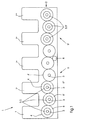
- the printing press 1 shows a printing press 1 with the torsional vibration damping according to the invention.
- the printing press 1 consists of five printing units 7, 7 ', 7'',7''', 7 ''', which are driven by a drive 8 via a gear train 2.
- the number of printing units is of course only an example.
- the drive 8 is expediently arranged in the central region of the printing press 1 in order to keep the force moments to be transmitted as low as possible.
- a printing cylinder 4 is assigned to each printing unit 7, 7 ', 7'',7''', 7 '''' and there are drums 4 'between the printing units for transferring the sheets from one printing unit to another.
- the cylinders 4 and the drums 4 ' are equipped with gears 6, 6', 6 '', ... which mesh with one another to form the gear train 2. If torsional vibrations occur in such a printing press 1, these are generally low in the drive 8 and increase with increasing distance from the drive 8.
- the first of such a printing press 1 is measured by torsional vibration and possibly also the second mode and frequency as well as the location of the Occurrence of the same is determined at specific points on this natural frequency and To use the inherent shape of coordinated passive torsional vibration absorbers 5, 5 '.
- With such a Machine with the drive 8 in the middle area should regularly every power transmission side 9 and 9 'are assigned at least one torsional vibration damper 5, 5'.
- Fig. 2 shows the arrangement of a first embodiment of a torsional vibration damper 5 or 5 '.
- a cylinder 4 or a drum 4 ' is shown, which is mounted on both sides in the side walls 19 of the printing press by means of bearings 20.
- the side wall 19 of the drive side is shown.
- the gear 6, 6 ', 6'', ... is located on the shaft journal 3, which is driven via the gear train 2 of the printing press 1. If corresponding amplitudes of the natural frequency have been measured for this cylinder 4 or this drum 4 ', the shaft journal 3 is provided according to the invention with a torsional vibration damper 5 or 5'.
- the illustrated first exemplary embodiment of a torsional vibration damper 5, 5 ' exists from a carrier 14, for example a flange, which is attached to the shaft journal 3 is.
- a carrier 14 On this carrier 14 there is an elastomer 11, which is a ring trained mass 10 carries.
- the elastomer 11 is designed such that it is repayment and Has damping properties.
- Fig. 3 shows a second embodiment of a torsional vibration damper 5, 5 '.
- the eradication properties are achieved by means of specific spring elements 12 and the damping properties are achieved by means of specific damping elements 13.
- these are arranged between a flange-like carrier 14 and the mass 10.
- the damping elements 13 consist of closed cylinders 15 in which pistons 16 run, the pistons 16 having a gap 18 through which a damping medium 17 can flow from one space to another.
- FIG. 4 shows a first exemplary embodiment of a two-stage torsional vibration damper 21.
- a carrier 14 with an elastomer 11 and a mass 10 is arranged on a shaft journal 3.
- a vibration which has amplitudes of the first and second orders can be reduced with a two-stage torsional vibration damper 21.
- FIG. 5 shows a second exemplary embodiment of a two-stage torsional vibration damper 21.
- the two torsional vibration dampers 5 and 5 ' are arranged next to one another on a carrier 14.
- the invention can be implemented with many other embodiments, for example the two-stage torsional vibration damper of FIGS. 4 and 5 in Art are formed as the torsional vibration damper 5, 5 ', which is shown in Fig. 3 and was explained above.
- torsional vibration damper 5 for the first and torsional vibration damper 5 'for the second mode and frequency of the pressure arrange the machine separately on the shaft journal 3. They can partially open the same shaft journal 3 or be arranged on different shaft journals 3.
- Further embodiments of the damping 13 and spring elements 12 are also conceivable or an embodiment in which a mass 10 or 10 'disc-shaped under Insertion of a repaying and / or damping element 11, 1 ', 12, 13 on the front side of the shaft journal 3 sits.
Landscapes
- Engineering & Computer Science (AREA)
- Mechanical Engineering (AREA)
- Rotary Presses (AREA)
- Vibration Prevention Devices (AREA)
- Inking, Control Or Cleaning Of Printing Machines (AREA)
- Rolls And Other Rotary Bodies (AREA)
- Accessory Devices And Overall Control Thereof (AREA)
Applications Claiming Priority (2)
| Application Number | Priority Date | Filing Date | Title |
|---|---|---|---|
| DE19914613A DE19914613A1 (de) | 1999-03-31 | 1999-03-31 | Verfahren und Vorrichtung zur Tilgung der Drehschwingungen einer Druckmaschine |
| DE19914613 | 1999-03-31 |
Publications (3)
| Publication Number | Publication Date |
|---|---|
| EP1040918A1 true EP1040918A1 (fr) | 2000-10-04 |
| EP1040918B1 EP1040918B1 (fr) | 2004-07-14 |
| EP1040918B2 EP1040918B2 (fr) | 2012-01-25 |
Family
ID=7903081
Family Applications (1)
| Application Number | Title | Priority Date | Filing Date |
|---|---|---|---|
| EP00104762A Expired - Lifetime EP1040918B2 (fr) | 1999-03-31 | 2000-03-04 | Procédé et dispositif pour amortir les vibrations de torsion d'une machine d'impression |
Country Status (5)
| Country | Link |
|---|---|
| US (1) | US6499401B1 (fr) |
| EP (1) | EP1040918B2 (fr) |
| JP (1) | JP2000313099A (fr) |
| AT (1) | ATE270967T1 (fr) |
| DE (2) | DE19914613A1 (fr) |
Cited By (1)
| Publication number | Priority date | Publication date | Assignee | Title |
|---|---|---|---|---|
| EP2181847A1 (fr) * | 2008-10-31 | 2010-05-05 | manroland AG | Unité d'impression |
Families Citing this family (8)
| Publication number | Priority date | Publication date | Assignee | Title |
|---|---|---|---|---|
| DE19963945C1 (de) * | 1999-12-31 | 2001-07-19 | Koenig & Bauer Ag | Verfahren und Anordnung zur Kompensation von Schwingungen rotierender Bauteile |
| DE10249475A1 (de) | 2001-11-20 | 2003-09-11 | Heidelberger Druckmasch Ag | Verfahren und Vorrichtung zum Unterdrücken von Schwingungen in einer drucktechnischen Maschine |
| DE10248519B4 (de) * | 2002-10-17 | 2006-11-02 | Voith Patent Gmbh | Mittelwalze eines Kalanders und Kalander |
| DE102007015345A1 (de) * | 2007-03-30 | 2008-10-02 | Koenig & Bauer Aktiengesellschaft | Vorrichtung zur Reduzierung von Schwingungen einer Greiferwelle |
| DE102009046745A1 (de) * | 2009-11-17 | 2011-05-19 | Man Diesel & Turbo Se | Kurbelwelle |
| DE102010026204A1 (de) * | 2010-07-02 | 2012-01-05 | Fakultät Ingenieurwissenschaften und Informatik Fachhochschule Onsabrück | Verfahren sowie Vorrichtung zur Kompensation von über den Umfang eines rotierenden insbesondere zylindrischen, Bauteils, insbesondere einer Walze, periodisch wiederkehrenden Störanregungen sowie Verfahren zur Bestimmung der Oberflächenstruktur eines ringförmigen Profils zur Kompensation der Störanregungen |
| DE102022212522A1 (de) * | 2022-11-23 | 2024-05-23 | Zf Friedrichshafen Ag | Zahnrad oder Welle mit Schwingungstilger |
| DE102023135919A1 (de) | 2023-12-20 | 2025-06-26 | Mahle International Gmbh | Dämpfungselement für ein Elektrofahrrad und ein Elektrofahrrad |
Citations (7)
| Publication number | Priority date | Publication date | Assignee | Title |
|---|---|---|---|---|
| US2581656A (en) * | 1947-04-25 | 1952-01-08 | Hoe & Co R | Bearing support for printing presses |
| US3058371A (en) * | 1960-11-29 | 1962-10-16 | Fred L Haushalter | Vibration dampener |
| FR2286983A1 (fr) * | 1974-10-05 | 1976-04-30 | Roland Offsetmaschf | Dispositif amortissant les inegalites de transmission dans un engrenage a pignons |
| DE2516462A1 (de) * | 1975-04-15 | 1976-10-28 | Roland Offsetmaschf | Schwingungsfreier antrieb fuer druckmaschinen |
| GB2046873A (en) * | 1979-02-23 | 1980-11-19 | Goetze Ag | Vibration damper for rotating shafts |
| GB2170882A (en) * | 1985-01-23 | 1986-08-13 | Fichtel & Sachs Ag | Torsional vibration damper |
| DE3529687A1 (de) * | 1985-08-20 | 1987-03-05 | Opel Adam Ag | Drehschwingungstilger fuer eine antriebswelle |
Family Cites Families (21)
| Publication number | Priority date | Publication date | Assignee | Title |
|---|---|---|---|---|
| DE130321C (fr) | ||||
| US4073047A (en) * | 1974-12-26 | 1978-02-14 | The Goodyear Tire & Rubber Company | Method of making vibration damper |
| DD130321A1 (de) * | 1977-04-12 | 1978-03-22 | Wolfgang Mey | Vorrichtung zur tilgung von torsionsschwingungen |
| JPS6131735U (ja) * | 1984-07-28 | 1986-02-26 | 三菱重工業株式会社 | 脈動トルクダンパ装置 |
| DE3626185A1 (de) * | 1986-08-01 | 1988-02-18 | Heidelberger Druckmasch Ag | Getriebe zur bildung einer zyklisch ablaufenden bewegung aus einer rotationsbewegung |
| JPH0356154Y2 (fr) * | 1986-09-02 | 1991-12-16 | ||
| DE3828638C1 (fr) * | 1988-08-24 | 1989-07-27 | Heidelberger Druckmaschinen Ag, 6900 Heidelberg, De | |
| JPH02146029U (fr) * | 1989-05-15 | 1990-12-11 | ||
| JP2895268B2 (ja) * | 1990-08-13 | 1999-05-24 | オイレス工業株式会社 | 塑性エネルギー吸収装置 |
| DE4033278C1 (fr) * | 1990-10-19 | 1992-03-12 | Heidelberger Druckmaschinen Ag, 6900 Heidelberg, De | |
| US5410228A (en) * | 1991-02-05 | 1995-04-25 | Kabushiki Kaisha Yaskawa Denki | Method and apparatus for suppressing torsional vibration in an electric motor speed control system |
| US5420664A (en) * | 1992-09-02 | 1995-05-30 | Konica Corporation | Driving apparatus for a rotary body in use with an image forming apparatus |
| JP3364514B2 (ja) * | 1992-09-02 | 2003-01-08 | コニカ株式会社 | 画像出力機器における回転体の駆動装置 |
| DE4234928A1 (de) * | 1992-10-16 | 1994-04-21 | Heidelberger Druckmasch Ag | Vorrichtung und Verfahren zur Dämpfung von mechanischen Schwingungen von Druckmaschinen |
| US5324248A (en) * | 1992-11-03 | 1994-06-28 | Composite Development Corporation | Composite machine roll and method of manufacture |
| FR2723625B1 (fr) * | 1994-08-09 | 1996-11-08 | Heidelberg Harris Sa | Procede et dispositif d'amortissement des vibrations en flexion des cylindres dans une presse a imprimer. |
| DE19508082C2 (de) † | 1995-03-08 | 2000-05-11 | Koenig & Bauer Ag | Hauptantrieb für eine Druckmaschine |
| US5752443A (en) | 1995-06-16 | 1998-05-19 | Heidelberger Druckmaschinen Ag | Mechanism for excluding critical speeds from normal operating ranges |
| JPH09151992A (ja) * | 1995-11-30 | 1997-06-10 | Nok Megurasutikku Kk | ダンパ |
| JP3742143B2 (ja) * | 1996-04-19 | 2006-02-01 | 株式会社三共製作所 | 変動トルク相殺装置 |
| US5794529A (en) * | 1996-05-02 | 1998-08-18 | Heidelberger Druckmaschinen Ag | Compliant drive for printing presses |
-
1999
- 1999-03-31 DE DE19914613A patent/DE19914613A1/de not_active Ceased
-
2000
- 2000-03-04 EP EP00104762A patent/EP1040918B2/fr not_active Expired - Lifetime
- 2000-03-04 DE DE50007037T patent/DE50007037D1/de not_active Expired - Lifetime
- 2000-03-04 AT AT00104762T patent/ATE270967T1/de not_active IP Right Cessation
- 2000-03-30 JP JP2000094016A patent/JP2000313099A/ja active Pending
- 2000-03-31 US US09/540,936 patent/US6499401B1/en not_active Expired - Lifetime
Patent Citations (7)
| Publication number | Priority date | Publication date | Assignee | Title |
|---|---|---|---|---|
| US2581656A (en) * | 1947-04-25 | 1952-01-08 | Hoe & Co R | Bearing support for printing presses |
| US3058371A (en) * | 1960-11-29 | 1962-10-16 | Fred L Haushalter | Vibration dampener |
| FR2286983A1 (fr) * | 1974-10-05 | 1976-04-30 | Roland Offsetmaschf | Dispositif amortissant les inegalites de transmission dans un engrenage a pignons |
| DE2516462A1 (de) * | 1975-04-15 | 1976-10-28 | Roland Offsetmaschf | Schwingungsfreier antrieb fuer druckmaschinen |
| GB2046873A (en) * | 1979-02-23 | 1980-11-19 | Goetze Ag | Vibration damper for rotating shafts |
| GB2170882A (en) * | 1985-01-23 | 1986-08-13 | Fichtel & Sachs Ag | Torsional vibration damper |
| DE3529687A1 (de) * | 1985-08-20 | 1987-03-05 | Opel Adam Ag | Drehschwingungstilger fuer eine antriebswelle |
Cited By (2)
| Publication number | Priority date | Publication date | Assignee | Title |
|---|---|---|---|---|
| EP2181847A1 (fr) * | 2008-10-31 | 2010-05-05 | manroland AG | Unité d'impression |
| US8418610B2 (en) | 2008-10-31 | 2013-04-16 | Manroland Ag | Printing unit |
Also Published As
| Publication number | Publication date |
|---|---|
| US6499401B1 (en) | 2002-12-31 |
| DE50007037D1 (de) | 2004-08-19 |
| EP1040918B2 (fr) | 2012-01-25 |
| ATE270967T1 (de) | 2004-07-15 |
| EP1040918B1 (fr) | 2004-07-14 |
| JP2000313099A (ja) | 2000-11-14 |
| DE19914613A1 (de) | 2000-10-05 |
Similar Documents
| Publication | Publication Date | Title |
|---|---|---|
| EP1040917B1 (fr) | Procédé et dispositif à compensation de vibrations torsionelles d'une machine à imprimer | |
| DE4447610C2 (de) | Schwingungstilger | |
| DE102010046072B4 (de) | Verfahren zum Dämpfen eines Rüttelns auf ebener Straße in einem elektrischen Servolenksystem | |
| EP0592850B1 (fr) | Dispositif et procédé pour amortir les vibrations mécaniques d'une machine à imprimer | |
| EP0462411B1 (fr) | Equilibrage du couple de deuxième ordre d'un moteur à combustion interne 5 cylindres en ligne | |
| DE3529199C2 (fr) | ||
| WO2011141246A1 (fr) | Amortisseur de vibrations | |
| DE2358516A1 (de) | Schwingungsdaempfer, insbesondere fuer verbrennungskraftmaschinen | |
| DE3428553C2 (fr) | ||
| EP1040918B1 (fr) | Procédé et dispositif pour amortir les vibrations de torsion d'une machine d'impression | |
| DE10233499B4 (de) | Geteilter, aktiver Kraftfahrzeugstabilisator mit einem Aktuator zur Wankregelung | |
| DE3316008C2 (fr) | ||
| DE10249475A1 (de) | Verfahren und Vorrichtung zum Unterdrücken von Schwingungen in einer drucktechnischen Maschine | |
| DE102017000193A1 (de) | Walze zur Bodenverdichtung sowie Verfahren zum Erzeugen eines Schwingungsbildes einer Walze zur Bodenverdichtung | |
| DE102007035476A1 (de) | Verfahren zum Betreiben einer Druckmaschine | |
| DE102008002454B4 (de) | Papiermaschinenwalze und Schwingungstilger | |
| DE102008039543B4 (de) | Rollenmühle | |
| EP0411349B1 (fr) | Dispositif pour compacter le sol | |
| DE102011084141B4 (de) | Antriebssystem mit einem Differentialdämpfer zur Drehungleichförmigkeitsreduktion | |
| DE102013101066B4 (de) | Rotationszylinder | |
| DE10002619B4 (de) | Vorrichtung zur Kompensation von Torsionsschwingungen für ein Kraftfahrzeug | |
| DE1630879B2 (de) | Antriebsanordnung fuer kraftfahrzeuge | |
| WO2002076741A1 (fr) | Mecanisme d'entrainement d'un groupe d'impression | |
| EP3292319A1 (fr) | Amortisseur à masse accordée adaptatif non amorti | |
| DE19960698B4 (de) | Vorrichtung zum internen Massenausgleich bei eigenchangierenden Walzen |
Legal Events
| Date | Code | Title | Description |
|---|---|---|---|
| PUAI | Public reference made under article 153(3) epc to a published international application that has entered the european phase |
Free format text: ORIGINAL CODE: 0009012 |
|
| AK | Designated contracting states |
Kind code of ref document: A1 Designated state(s): AT BE CH CY DE DK ES FI FR GB GR IE IT LI LU MC NL PT SE |
|
| AX | Request for extension of the european patent |
Free format text: AL;LT;LV;MK;RO;SI |
|
| 17P | Request for examination filed |
Effective date: 20000826 |
|
| AKX | Designation fees paid |
Free format text: AT BE CH CY DE DK ES FI FR GB GR IE IT LI LU MC NL PT SE |
|
| 17Q | First examination report despatched |
Effective date: 20010406 |
|
| GRAP | Despatch of communication of intention to grant a patent |
Free format text: ORIGINAL CODE: EPIDOSNIGR1 |
|
| GRAS | Grant fee paid |
Free format text: ORIGINAL CODE: EPIDOSNIGR3 |
|
| GRAA | (expected) grant |
Free format text: ORIGINAL CODE: 0009210 |
|
| AK | Designated contracting states |
Kind code of ref document: B1 Designated state(s): AT BE CH CY DE DK ES FI FR GB GR IE IT LI LU MC NL PT SE |
|
| PG25 | Lapsed in a contracting state [announced via postgrant information from national office to epo] |
Ref country code: NL Free format text: LAPSE BECAUSE OF FAILURE TO SUBMIT A TRANSLATION OF THE DESCRIPTION OR TO PAY THE FEE WITHIN THE PRESCRIBED TIME-LIMIT Effective date: 20040714 Ref country code: IE Free format text: LAPSE BECAUSE OF FAILURE TO SUBMIT A TRANSLATION OF THE DESCRIPTION OR TO PAY THE FEE WITHIN THE PRESCRIBED TIME-LIMIT Effective date: 20040714 Ref country code: FI Free format text: LAPSE BECAUSE OF FAILURE TO SUBMIT A TRANSLATION OF THE DESCRIPTION OR TO PAY THE FEE WITHIN THE PRESCRIBED TIME-LIMIT Effective date: 20040714 |
|
| REG | Reference to a national code |
Ref country code: GB Ref legal event code: FG4D Free format text: NOT ENGLISH |
|
| REG | Reference to a national code |
Ref country code: CH Ref legal event code: EP |
|
| REF | Corresponds to: |
Ref document number: 50007037 Country of ref document: DE Date of ref document: 20040819 Kind code of ref document: P |
|
| REG | Reference to a national code |
Ref country code: IE Ref legal event code: FG4D Free format text: GERMAN |
|
| GBT | Gb: translation of ep patent filed (gb section 77(6)(a)/1977) |
Effective date: 20040811 |
|
| PG25 | Lapsed in a contracting state [announced via postgrant information from national office to epo] |
Ref country code: GR Free format text: LAPSE BECAUSE OF FAILURE TO SUBMIT A TRANSLATION OF THE DESCRIPTION OR TO PAY THE FEE WITHIN THE PRESCRIBED TIME-LIMIT Effective date: 20041014 Ref country code: SE Free format text: LAPSE BECAUSE OF FAILURE TO SUBMIT A TRANSLATION OF THE DESCRIPTION OR TO PAY THE FEE WITHIN THE PRESCRIBED TIME-LIMIT Effective date: 20041014 Ref country code: DK Free format text: LAPSE BECAUSE OF FAILURE TO SUBMIT A TRANSLATION OF THE DESCRIPTION OR TO PAY THE FEE WITHIN THE PRESCRIBED TIME-LIMIT Effective date: 20041014 |
|
| PG25 | Lapsed in a contracting state [announced via postgrant information from national office to epo] |
Ref country code: ES Free format text: LAPSE BECAUSE OF FAILURE TO SUBMIT A TRANSLATION OF THE DESCRIPTION OR TO PAY THE FEE WITHIN THE PRESCRIBED TIME-LIMIT Effective date: 20041025 |
|
| NLV1 | Nl: lapsed or annulled due to failure to fulfill the requirements of art. 29p and 29m of the patents act | ||
| PG25 | Lapsed in a contracting state [announced via postgrant information from national office to epo] |
Ref country code: CY Free format text: LAPSE BECAUSE OF FAILURE TO SUBMIT A TRANSLATION OF THE DESCRIPTION OR TO PAY THE FEE WITHIN THE PRESCRIBED TIME-LIMIT Effective date: 20050304 Ref country code: LU Free format text: LAPSE BECAUSE OF NON-PAYMENT OF DUE FEES Effective date: 20050304 |
|
| PGFP | Annual fee paid to national office [announced via postgrant information from national office to epo] |
Ref country code: AT Payment date: 20050318 Year of fee payment: 6 Ref country code: BE Payment date: 20050318 Year of fee payment: 6 |
|
| REG | Reference to a national code |
Ref country code: IE Ref legal event code: FD4D |
|
| ET | Fr: translation filed | ||
| PG25 | Lapsed in a contracting state [announced via postgrant information from national office to epo] |
Ref country code: MC Free format text: LAPSE BECAUSE OF NON-PAYMENT OF DUE FEES Effective date: 20050331 |
|
| PLAQ | Examination of admissibility of opposition: information related to despatch of communication + time limit deleted |
Free format text: ORIGINAL CODE: EPIDOSDOPE2 |
|
| PLBQ | Unpublished change to opponent data |
Free format text: ORIGINAL CODE: EPIDOS OPPO |
|
| PLBI | Opposition filed |
Free format text: ORIGINAL CODE: 0009260 |
|
| PLAQ | Examination of admissibility of opposition: information related to despatch of communication + time limit deleted |
Free format text: ORIGINAL CODE: EPIDOSDOPE2 |
|
| PLAR | Examination of admissibility of opposition: information related to receipt of reply deleted |
Free format text: ORIGINAL CODE: EPIDOSDOPE4 |
|
| PLAX | Notice of opposition and request to file observation + time limit sent |
Free format text: ORIGINAL CODE: EPIDOSNOBS2 |
|
| PLBQ | Unpublished change to opponent data |
Free format text: ORIGINAL CODE: EPIDOS OPPO |
|
| PLAB | Opposition data, opponent's data or that of the opponent's representative modified |
Free format text: ORIGINAL CODE: 0009299OPPO |
|
| 26 | Opposition filed |
Opponent name: KOENIG & BAUER AKTIENGESELLSCHAFT Effective date: 20050413 |
|
| R26 | Opposition filed (corrected) |
Opponent name: KOENIG & BAUER AKTIENGESELLSCHAFT Effective date: 20050413 |
|
| PLBB | Reply of patent proprietor to notice(s) of opposition received |
Free format text: ORIGINAL CODE: EPIDOSNOBS3 |
|
| PG25 | Lapsed in a contracting state [announced via postgrant information from national office to epo] |
Ref country code: AT Free format text: LAPSE BECAUSE OF NON-PAYMENT OF DUE FEES Effective date: 20060304 |
|
| PG25 | Lapsed in a contracting state [announced via postgrant information from national office to epo] |
Ref country code: BE Free format text: LAPSE BECAUSE OF NON-PAYMENT OF DUE FEES Effective date: 20060331 |
|
| BERE | Be: lapsed |
Owner name: *HEIDELBERGER DRUCKMASCHINEN A.G. Effective date: 20060331 |
|
| PG25 | Lapsed in a contracting state [announced via postgrant information from national office to epo] |
Ref country code: PT Free format text: LAPSE BECAUSE OF NON-PAYMENT OF DUE FEES Effective date: 20041214 |
|
| PGFP | Annual fee paid to national office [announced via postgrant information from national office to epo] |
Ref country code: CH Payment date: 20090326 Year of fee payment: 10 Ref country code: GB Payment date: 20090324 Year of fee payment: 10 |
|
| REG | Reference to a national code |
Ref country code: CH Ref legal event code: PL |
|
| GBPC | Gb: european patent ceased through non-payment of renewal fee |
Effective date: 20100304 |
|
| PG25 | Lapsed in a contracting state [announced via postgrant information from national office to epo] |
Ref country code: CH Free format text: LAPSE BECAUSE OF NON-PAYMENT OF DUE FEES Effective date: 20100331 Ref country code: LI Free format text: LAPSE BECAUSE OF NON-PAYMENT OF DUE FEES Effective date: 20100331 |
|
| PG25 | Lapsed in a contracting state [announced via postgrant information from national office to epo] |
Ref country code: GB Free format text: LAPSE BECAUSE OF NON-PAYMENT OF DUE FEES Effective date: 20100304 |
|
| PUAH | Patent maintained in amended form |
Free format text: ORIGINAL CODE: 0009272 |
|
| STAA | Information on the status of an ep patent application or granted ep patent |
Free format text: STATUS: PATENT MAINTAINED AS AMENDED |
|
| 27A | Patent maintained in amended form |
Effective date: 20120125 |
|
| AK | Designated contracting states |
Kind code of ref document: B2 Designated state(s): AT BE CH CY DE DK ES FI FR GB GR IE IT LI LU MC NL PT SE |
|
| REG | Reference to a national code |
Ref country code: DE Ref legal event code: R102 Ref document number: 50007037 Country of ref document: DE |
|
| REG | Reference to a national code |
Ref country code: DE Ref legal event code: R102 Ref document number: 50007037 Country of ref document: DE Effective date: 20120125 |
|
| PGFP | Annual fee paid to national office [announced via postgrant information from national office to epo] |
Ref country code: IT Payment date: 20120322 Year of fee payment: 13 |
|
| PGFP | Annual fee paid to national office [announced via postgrant information from national office to epo] |
Ref country code: FR Payment date: 20130419 Year of fee payment: 14 |
|
| REG | Reference to a national code |
Ref country code: FR Ref legal event code: ST Effective date: 20141128 |
|
| PG25 | Lapsed in a contracting state [announced via postgrant information from national office to epo] |
Ref country code: FR Free format text: LAPSE BECAUSE OF NON-PAYMENT OF DUE FEES Effective date: 20140331 |
|
| PG25 | Lapsed in a contracting state [announced via postgrant information from national office to epo] |
Ref country code: IT Free format text: LAPSE BECAUSE OF NON-PAYMENT OF DUE FEES Effective date: 20140304 |
|
| PGFP | Annual fee paid to national office [announced via postgrant information from national office to epo] |
Ref country code: DE Payment date: 20170331 Year of fee payment: 18 |
|
| REG | Reference to a national code |
Ref country code: DE Ref legal event code: R119 Ref document number: 50007037 Country of ref document: DE |
|
| PG25 | Lapsed in a contracting state [announced via postgrant information from national office to epo] |
Ref country code: DE Free format text: LAPSE BECAUSE OF NON-PAYMENT OF DUE FEES Effective date: 20181002 |