EP1043185A2 - Bouchon avec patte d'attache - Google Patents
Bouchon avec patte d'attache Download PDFInfo
- Publication number
- EP1043185A2 EP1043185A2 EP00105482A EP00105482A EP1043185A2 EP 1043185 A2 EP1043185 A2 EP 1043185A2 EP 00105482 A EP00105482 A EP 00105482A EP 00105482 A EP00105482 A EP 00105482A EP 1043185 A2 EP1043185 A2 EP 1043185A2
- Authority
- EP
- European Patent Office
- Prior art keywords
- electroconductive resin
- coupling member
- string
- cap
- electroconductive
- Prior art date
- Legal status (The legal status is an assumption and is not a legal conclusion. Google has not performed a legal analysis and makes no representation as to the accuracy of the status listed.)
- Granted
Links
- 239000011347 resin Substances 0.000 claims abstract description 214
- 229920005989 resin Polymers 0.000 claims abstract description 214
- 230000008878 coupling Effects 0.000 claims abstract description 169
- 238000010168 coupling process Methods 0.000 claims abstract description 169
- 238000005859 coupling reaction Methods 0.000 claims abstract description 169
- 229920000642 polymer Polymers 0.000 claims description 49
- OKTJSMMVPCPJKN-UHFFFAOYSA-N Carbon Chemical compound [C] OKTJSMMVPCPJKN-UHFFFAOYSA-N 0.000 claims description 44
- 239000000835 fiber Substances 0.000 claims description 19
- 239000004721 Polyphenylene oxide Substances 0.000 claims description 18
- 229920001400 block copolymer Polymers 0.000 claims description 18
- 239000002184 metal Substances 0.000 claims description 18
- 229910052751 metal Inorganic materials 0.000 claims description 18
- 229920000570 polyether Polymers 0.000 claims description 18
- 229920000049 Carbon (fiber) Polymers 0.000 claims description 17
- 239000004917 carbon fiber Substances 0.000 claims description 17
- 229910052799 carbon Inorganic materials 0.000 claims description 15
- 239000000203 mixture Substances 0.000 claims description 15
- 239000000843 powder Substances 0.000 claims description 11
- 230000005611 electricity Effects 0.000 abstract description 24
- 230000003068 static effect Effects 0.000 abstract description 24
- 230000035939 shock Effects 0.000 abstract description 21
- 208000028659 discharge Diseases 0.000 description 37
- 238000005452 bending Methods 0.000 description 11
- 230000008901 benefit Effects 0.000 description 11
- 238000010586 diagram Methods 0.000 description 7
- 239000000463 material Substances 0.000 description 7
- 238000011156 evaluation Methods 0.000 description 6
- 108010036050 human cationic antimicrobial protein 57 Proteins 0.000 description 6
- 239000002828 fuel tank Substances 0.000 description 4
- 229920001971 elastomer Polymers 0.000 description 3
- 239000000806 elastomer Substances 0.000 description 3
- 229920000728 polyester Polymers 0.000 description 3
- 239000004952 Polyamide Substances 0.000 description 2
- 230000008859 change Effects 0.000 description 2
- 238000007599 discharging Methods 0.000 description 2
- 230000005489 elastic deformation Effects 0.000 description 2
- 238000000034 method Methods 0.000 description 2
- 229920002647 polyamide Polymers 0.000 description 2
- 230000008569 process Effects 0.000 description 2
- RYGMFSIKBFXOCR-UHFFFAOYSA-N Copper Chemical compound [Cu] RYGMFSIKBFXOCR-UHFFFAOYSA-N 0.000 description 1
- 229920002302 Nylon 6,6 Polymers 0.000 description 1
- 150000001408 amides Chemical class 0.000 description 1
- 239000006229 carbon black Substances 0.000 description 1
- 238000013329 compounding Methods 0.000 description 1
- 239000010949 copper Substances 0.000 description 1
- 229910052802 copper Inorganic materials 0.000 description 1
- 238000005516 engineering process Methods 0.000 description 1
- 150000002148 esters Chemical class 0.000 description 1
- 238000002474 experimental method Methods 0.000 description 1
- 229920005570 flexible polymer Polymers 0.000 description 1
- 238000003780 insertion Methods 0.000 description 1
- 230000037431 insertion Effects 0.000 description 1
- 238000012986 modification Methods 0.000 description 1
- 230000004048 modification Effects 0.000 description 1
- 230000002093 peripheral effect Effects 0.000 description 1
- 230000002035 prolonged effect Effects 0.000 description 1
- 229910001220 stainless steel Inorganic materials 0.000 description 1
- 239000010935 stainless steel Substances 0.000 description 1
Images






Classifications
-
- B—PERFORMING OPERATIONS; TRANSPORTING
- B60—VEHICLES IN GENERAL
- B60K—ARRANGEMENT OR MOUNTING OF PROPULSION UNITS OR OF TRANSMISSIONS IN VEHICLES; ARRANGEMENT OR MOUNTING OF PLURAL DIVERSE PRIME-MOVERS IN VEHICLES; AUXILIARY DRIVES FOR VEHICLES; INSTRUMENTATION OR DASHBOARDS FOR VEHICLES; ARRANGEMENTS IN CONNECTION WITH COOLING, AIR INTAKE, GAS EXHAUST OR FUEL SUPPLY OF PROPULSION UNITS IN VEHICLES
- B60K15/00—Arrangement in connection with fuel supply of combustion engines or other fuel consuming energy converters, e.g. fuel cells; Mounting or construction of fuel tanks
- B60K15/03—Fuel tanks
- B60K15/04—Tank inlets
- B60K15/0406—Filler caps for fuel tanks
-
- B—PERFORMING OPERATIONS; TRANSPORTING
- B60—VEHICLES IN GENERAL
- B60K—ARRANGEMENT OR MOUNTING OF PROPULSION UNITS OR OF TRANSMISSIONS IN VEHICLES; ARRANGEMENT OR MOUNTING OF PLURAL DIVERSE PRIME-MOVERS IN VEHICLES; AUXILIARY DRIVES FOR VEHICLES; INSTRUMENTATION OR DASHBOARDS FOR VEHICLES; ARRANGEMENTS IN CONNECTION WITH COOLING, AIR INTAKE, GAS EXHAUST OR FUEL SUPPLY OF PROPULSION UNITS IN VEHICLES
- B60K15/00—Arrangement in connection with fuel supply of combustion engines or other fuel consuming energy converters, e.g. fuel cells; Mounting or construction of fuel tanks
- B60K15/03—Fuel tanks
- B60K2015/03328—Arrangements or special measures related to fuel tanks or fuel handling
- B60K2015/03401—Arrangements or special measures related to fuel tanks or fuel handling for preventing electrostatic charges
Definitions
- the present invention relates to a string-attached cap in which one end of an elongated coupling member is connected to a cap.
- a cap In a fuel tank of an automobile, a cap is, in general, connected to the fuel tank by means of an elongated coupling member to prevent the loss of the cap during re-fueling.
- string-attached caps those disclosed in, for example, Japanese Patent Publications No. Hei. 3-295723 and Sho. 62-173321 or the like are known.
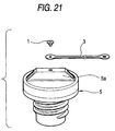
- Fig. 21 shows the string-attached cap disclosed in Japanese Patent Publication No. Hei. 3-295723, and in this string-attached cap one end of a coupling member 13 is connected to a handle portion 5a of a cap 5 by means of a fixing member 1.
- Fig. 22 shows this string-attached cap.
- This string-attached cap is arranged such that a coupling member 13, which is formed of flexible resin, has a ring part 13a formed integrally at one end thereof, and an engaging part 13b formed integrally with the inner periphery of the ring part 13a is rotatably engaged in an annular groove lid formed in the outer periphery of a cap 11.
- the engaging part 13b at the inner periphery of the ring part 13a is elastically deformed, and if the cap 11 in this state is inserted up to the annular groove 11d, the engaging part 13b is restored to its original state and is engaged in the annular groove 11d, so that the number of assembling steps can be substantially reduced as compared with the conventional art.
- the string-attached cap since a countermeasure against static electricity is not provided, at the time of removing the cap from the fuel tank, there is the risk of occurrence of spark discharge as static electricity charged in the human body is discharged through fingers and the like which came into contact with the cap.
- the electroconductive material can be constituted by, for example, an electroconductive resin; however, in the compounding of the electroconductive material which is mixed into it, there is the possibility that the following problem can be occur.
- the amount of the electroconductive material mixed is extremely small, electric conduction is lowered, and the discharge of static electricity does not take place completely, so that there are cases where the remaining static electricity causes secondary spark discharge.
- the amount of the electroconductive material mixed is extremely large, although electric conduction is enhanced, there can arise cases in which the moment the human body comes into contact with the cap, the human body receives a large shock.
- the present invention has been devised to overcome the above-described problems of the conventional art, and its object is to provide a string-attached cap which is capable of discharging static electricity without imparting a shock to the human body and of positively preventing the occurrence of secondary spark discharge.
- a string-attached cap comprising: a capping member formed of a first electroconductive resin; and an elongated coupling member having one end connected to the capping member, the elongated coupling member being formed of a second electroconductive resin and being flexible, and the string-attached cap being used with another end of the coupling member coupled to a vehicle, wherein the first electroconductive resins and the second electroconductive resin are formed such that surface resistance from the capping member to the vehicle is set to be greater than or equal to 1 X 10 12 ⁇ and less than 5.30 X 10 12 ⁇ .
- a string-attached cap comprising: a capping member formed of a first electroconductive resin; an elongated coupling member formed of a second electroconductive resin and being flexible; and a fastening member formed of a third electroconductive resin for fastening one end of the coupling member to the capping member, the string-attached cap being used with another end of the coupling member coupled to a vehicle, wherein the first electroconductive resins, the second electroconductive resin, and the third electroconductive resin are formed such that surface resistance from the capping member to the vehicle is set to be greater than or equal to 1 X 10 12 ⁇ and less than 5.30 X 10 12 ⁇ .
- a string-attached cap comprising: a capping member formed of a first electroconductive resin; a ring member engaged in an outer periphery of the capping member; an elongated coupling member formed of a second electroconductive resin which is flexible; and a fastening member formed of a third electroconductive resin for fastening one end of the coupling member to the ring member, the ring member being formed of a fourth electroconductive resin, the string-attached cap being used with another end of the coupling member coupled to a vehicle, wherein the first electroconductive resins, the second electroconductive resin, the third electroconductive resin, and the fourth electroconductive resin are formed such that surface resistance from the capping member to the vehicle is set to be greater than or equal to 1 X 10 12 ⁇ and less than 5.30 X 10 12 ⁇ .
- a string-attached cap comprising: a capping member formed of a first electroconductive resin and having an annular groove formed in its outer periphery; and an elongated coupling member formed of a second electroconductive resin and being flexible, the coupling member having a ring member formed integrally at one end thereof, an engaging part which is formed integrally with an inner periphery of the ring part being rotatably engaged in the annular groove of the capping member, the string-attached cap being used with another end of the coupling member coupled to a vehicle, wherein the first electroconductive resins and the second electroconductive resin are formed such that surface resistance from the capping member to the vehicle is set to be greater than or equal to 1 X 10 12 ⁇ and less than 5.30 X 10 12 ⁇ .
- all of the electroconductive resins in the aforementioned aspects are each formed of a mixture of an insulating polymer and one of carbon powders, carbon fibers and metal fibers in the string-attached cap according to the first to fourth aspects of the present invention.
- the second electroconductive resin for forming the coupling member has its insulating component consisting of an insulating polymer of a block copolymer including a hard segment and a soft segment, the soft segment containing a polyether component in the string-attached cap according to the fifth aspect of the present invention.
- the first lectroconductive resin for forming the capping member and the second electroconductive resin for forming the coupling member are each formed of a mixture of an insulating polymer and carbon powder, a content of the carbon powder being set in a range of from 4% to 9% as weight percentage for the first electroconductive resin and in a range of from 3% to 5% as weight percentage for the second electroconductive resin, a combination in which the content thereof in the first electroconductive resin is 9% and the content thereof in the second electroconductive resin is 5% as well as combinations in which the content thereof in the first electroconductive resin is in a range of from 4% to 5% and the content thereof in the second electroconductive resin is in a range of from 3% to 4% are being excluded in the string-attached cap according to the fifth and sixth aspects of the present invention.
- a string-attached cap comprising: a capping member formed of a first electroconductive resin; and an elongated coupling member having one end connected to the capping member, the elongated coupling member being formed of a second electroconductive resin and being flexible, wherein the first electroconductive resin and the second electroconductive resin are each formed of a mixture of an insulating polymer and one of carbon powders, carbon fibers and metal fibers, and the insulating polymer of the second electroconductive resin is formed of an insulating polymer of a block copolymer including a hard segment and a soft segment, the soft segment containing a polyether component.
- a string-attached cap comprising: a capping member formed of a first electroconductive resin; an elongated coupling member formed of a second electroconductive resin and being flexible; and a fastening member formed of a third electroconductive resin for fastening one end of the coupling member to the capping member, wherein the first electroconductive resin, the second electroconductive resin and the third electroconductive resin are each formed of a mixture of an insulating polymer and one of carbon powders, carbon fibers and metal fibers, and the insulating polymer of the second electroconductive resin is formed of an insulating polymer of a block copolymer including a hard segment and a soft segment, the soft segment containing a polyether component.
- a string-attached cap comprising: a capping member formed of a first electroconductive resin; a ring member engaged in an outer periphery of the capping member; an elongated coupling member formed of a second electroconductive resin which is flexible; and a fastening member formed of a third electroconductive resin for fastening one end of the coupling member to the ring member, wherein the ring member is formed of a fourth electroconductive resin, and the first electroconductive resin, the second electroconductive resin, the third electroconductive resin and the fourth electroconductive resin are each formed of a mixture of an insulating polymer and one of carbon powders, carbon fibers and metal fibers, and the insulating polymer of the second electroconductive resin is formed of an insulating polymer of a block copolymer including a hard segment and a soft segment, the soft segment containing a polyether component.
- a string-attached cap comprising: a capping member formed of a first electroconductive resin and having an annular groove formed in its outer periphery; and an elongated coupling member formed of a second electroconductive resin and being flexible, the coupling member having a ring member formed integrally at one end thereof, an engaging part which is formed integrally with an inner periphery of the ring part being rotatably engaged in the annular groove of the capping member, the string-attached cap being used with another end of the coupling member coupled to a vehicle, wherein the first electroconductive resin and the second electroconductive resin are each formed of a mixture of an insulating polymer and one of carbon powders, carbon fibers and metal fibers, and the insulating polymer of the second electroconductive resin is formed of an insulating polymer of a block copolymer including a hard segment and a soft segment, the soft segment containing a polyether component.
- the capping member and the elongated coupling member are coupled to each other and are respectively formed of a first electroconductive resin and a second electroconductive resin, the string-attached cap can be maintained at the same potential as that of the vehicle body.
- first electroconductive resin and the second electroconductive resin are formed such that surface resistance from the capping member to the vehicle is set to be greater than or equal to 1 X 10 12 ⁇ and less than 5.30 X 10 12 ⁇ , when the human body is brought into contact with the capping member and static electricity charged in the human body is discharged to the vehicle side, a discharge shock is not imparted to the hand or fingers, and secondary spark discharge does not occur since the amount of residual discharge after the discharge becomes that of a critical value of spark discharge.
- the capping member and the elongated coupling member are coupled to each other by the fastening member, and the members are respectively formed of the first electroconductive resin, the second electroconductive resin, and the third electroconductive resin, the string-attached cap can be maintained at the same potential as that of the vehicle body.
- first electroconductive resin and the second electroconductive resin are formed such that surface resistance from the capping member to the vehicle is set to be greater than or equal to 1 X 10 12 ⁇ and less than 5.30 X 10 12 ⁇ , when discharge of static electricity is allowed to take place in the same way as in the invention according to the first aspect, advantages are obtained in that no discharge shock is imparted to the human body, and that the secondary spark discharge does not occur after the discharge.
- the ring member is engaged in the outer periphery of the capping member, the ring member and the elongated coupling member are coupled to each other by the fastening member, and the members are respectively formed of the first electroconductive resin, the second electroconductive resin, and the third electroconductive resin, and the fourth electroconductive resin. Therefore, the string-attached cap can be maintained at the same potential as that of the vehicle body.
- first electroconductive resin, the second electroconductive resin, the third electroconductive resin, and the fourth electroconductive resin are formed such that surface resistance from the capping member to the vehicle is set to be greater than or equal to 1 X 10 12 ⁇ and less than 5.30 X 10 12 ⁇ , when discharge of static electricity is allowed to take place in the same way as in the above-described invention, advantages are obtained in that no shock is imparted to the human body, and that the secondary spark discharge due to the amount of residual charge does not occur.
- the capping member can be rotated freely with respect to the ring member, advantages can be obtained in that when the capping member is opened or closed, the deformation of the coupling member can be held down to a small level, and that opening and closing can be effected smoothly.
- the annular groove is formed in the outer periphery of the capping member
- the elongated coupling member has the ring part formed integrally at one end thereof
- the engaging part formed integrally with the inner periphery of the ring part is rotatably engaged in the annular groove of the capping member and is coupled to the capping member
- the members are respectively formed of the first electroconductive resin and the second electroconductive resin. Therefore, the string-attached cap can be maintained at the same potential as that of the vehicle body.
- first electroconductive resin and the second electroconductive resin are respectively formed such that surface resistance from the capping member to the vehicle is set to be greater than or equal to 1 X 10 12 ⁇ and less than 5.30 X 10 12 ⁇ , when discharge of static electricity is allowed to take place in the same way as in the above-described invention, advantages are obtained in that no shock is imparted to the human body, and that the secondary spark discharge does not occur after the discharge.
- the capping member can be rotated freely with respect to the ring member of the coupling member, when the capping member is opened or closed, the deformation of the coupling member can be held down to a small level, and opening and closing can be effected smoothly.
- the coupling member is flexible, if the capping member is inserted into the ring part of the coupling member, the engaging part at the inner periphery of the ring part is elastically deformed, and if, in this state, the capping member is pushed in up to the annular groove, the engaging part is restored to its original state and is engaged in the annular groove. Therefore, the number of assembling steps can be substantially reduced as compared with the conventional art.
- the electroconductive resin is formed by mixing carbon powder, carbon fibers, or metal fibers with an insulating polymer, it is possible to increase the strength of the coupling member while obtaining predetermined surface resistance.
- an insulating polymer of a block copolymer including a hard segment and a soft segment containing a polyether component is used as the insulating polymer for forming the coupling member, advantages are obtained in that high bending properties are obtained even at a low temperature, and the coupling member does not become damaged due to fatigue caused by repeated deformation accompanying the opening and closing of the capping member.
- the content of the carbon powder being set in a range of from 4% to 9% as weight percentage for the first electroconductive resin and in a range of from 3% to 5% as weight percentage for the second electroconductive resin, and a combination in which the content thereof in the first electroconductive resin is 9% and the content thereof in the second electroconductive resin is 5% as well as combinations in which the content thereof in the first electroconductive resin is in a range of from 4% to 5% and the content thereof in the second electroconductive resin is in a range of from 3% to 4% are excluded. Therefore, the surface resistance from the capping member to the vehicle can be set to be greater than or equal to 1 X 10 12 ⁇ and less than 5.30 X 10 12 ⁇ .
- the electroconductive resin for forming each of the members is formed by mixing carbon powder, carbon fibers, or metal fibers with an insulating polymer, it is possible to increase the strength of the members.
- an insulating polymer of a block copolymer including a hard segment and a soft segment containing a polyether component is used as the insulating polymer for the second electroconductive resin for forming the coupling member, it is possible to obtain a coupling member which is flexible, maintains high bending properties even at a low temperature, and does not become damaged due to fatigue caused by repeated deformation accompanying the opening and closing of the capping member.
- the electroconductive resin for forming each of the members is formed by mixing carbon powder, carbon fibers, or metal fibers with an insulating polymer, it is possible to increase the strength of the members.
- an insulating polymer of a block copolymer including a hard segment and a soft segment containing a polyether component is used for the second electroconductive resin for forming the coupling member, it is possible to obtain a coupling member which is flexible, maintains sufficient bending properties even at a low temperature, and does not become damaged due to fatigue caused by repeated deformation accompanying the opening and closing of the capping member.
- the electroconductive resin for forming each of the members is formed by mixing carbon powder, carbon fibers, or metal fibers with an insulating polymer, it is possible to increase the strength of the members. Since an insulating polymer of a block copolymer including a hard segment and a soft segment containing a polyether component is used for the second electroconductive resin for forming the coupling member, it is possible to obtain a coupling member which is flexible, maintains sufficient bending properties even at a low temperature, and does not become damaged due to fatigue caused by repeated deformation accompanying the opening and closing of the capping member.
- the electroconductive resin for forming each of the members is formed by mixing carbon powder, carbon fibers, or metal fibers with an insulating polymer, it is possible to increase the strength of the members. Since an insulating polymer of a block copolymer including a hard segment and a soft segment containing a polyether component is used for the second electroconductive resin for forming the coupling member, it is possible to obtain a coupling member which is flexible, maintains sufficient bending properties even at a low temperature, and does not become damaged due to fatigue caused by repeated deformation accompanying the opening and closing of the capping member.
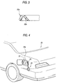
- Figs. 1 and 2 show a first embodiment of the string-attached cap in accordance with the present invention.
- Fig. 1 is a side view
- Fig. 2 is a top view.
- reference numeral 21 denotes a cap for a fuel tank of an automobile.
- This cap 21 is formed of an electroconductive resin, and a handle portion 21b is formed on one side of a cap body 21a, and a threaded part 21c on the other side thereof.
- An annular groove 21d is formed in the outer periphery of the cap body 21a.
- Reference numeral 23 denotes an elongated flexible coupling member formed of an electroconductive resin.
- An annular ring part 23a is formed integrally at one end of the coupling member 23.
- this ring part 23a in its cross-sectional shape is formed in an inverse v-shape, and its inner peripheral side is formed as an engaging part 23b.
- This engaging part 23b is rotatably engaged in the annular groove 21d formed in the outer periphery of the cap body 21a.
- an attaching portion 23c is formed integrally at the other end of the coupling member 23, and an attaching member 23d for attachment to the vehicle is formed in this attaching portion 23c.
- the string-attached cap thus constructed is used as the attaching portion 23c formed at the other end of the coupling member 23 is rotatably fixed to a vehicle body 27 of an automobile 25 by means of the attaching member 23d.
- the electroconductive resin for forming the cap 21 and the coupling member 23 is formed by mixing carbon powder (carbon black) into a flexible insulating polymer.
- the content of the carbon powder to be mixed in is determined such that when the human body charged with static electricity comes into contact with the handle portion 21b, no shock is imparted to the hand or fingers, and secondary spark discharge does is not caused by the amount of residual charge.
- the amount of residual charge was measured by conducting an organoleptic evaluation in a number of combinations by varying the respective contents in the cap 21 and the coupling member 23.
- Fig. 5 is a diagram illustrating the results of surface resistance and organoleptic evaluation measured by varying the content of carbon powder in the coupling member 23 and the cap 21.
- Curves a , b , c , and d respectively show surface resistance values measured by varying its content in the cap 21 from 4 % to 9% when its content (weight ratio) in the coupling member 23 was set to 3%, 4%, 5%, and 6%.
- the organoleptic evaluation was conducted with respect to combinations of the contents at three levels, including A in which no shock is felt, B in which a slight shock is felt, and C in which a strong shock is felt. Consequently, as shown in Fig. 5, in the region where the surface resistance was 10 8 ⁇ or less, a strong shock at C level (X) was felt. Meanwhile, in the region from 10 8 ⁇ to 10 12 ⁇ , the level was B level ( ⁇ ), and in only the region higher than or equal to 10 12 ⁇ , the level was A level (O) in which no shock was felt. Accordingly, in order not to feel a shock, it is necessary to render the surface resistance higher than or equal to 10 12 ⁇ .
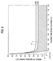
- Fig. 6 is a diagram illustrating a change over time of the amount of residual charge. Curves e , f , and g , are discharge curves showing the amounts of residual charge in the combination 1, combination 2, and combination 3, respectively.
- the amount of residual charge stabilized at 2.5 kV and 2.0 kV, respectively, after the lapse of 0.4 second upon touching, as shown by the curves e and f .
- the amount of residual charge was 0 after the lapse of 0.16 second at shown by the curve g .
- the critical voltage of the spark discharge in the air is 2 kV (referring to "safety guide for static electricity" published by Technology Institution of Industrial Safety in Japan, 1988)
- the surface resistance is set to a level less than or equal to that of the combination 2 in which the amount of residual charge stabilizes at 2.0 kV, the amount of residual charge becomes 2.0 kV or less, so that the secondary spark charge becomes difficult to occur.
- the surface resistance of the combination 2 is 5.30 X 10 12 ⁇ .
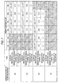
- Fig. 7 is a diagram which shows the relationship among the carbon contents, surface resistance, the amount of residual charge, and the organoleptic evaluation.
- the carbon powder content of the cap 21 is in the range of from 4% to 5% and the carbon powder content of the coupling member 23 is in the range of from 3% to 4%, the amount of residual charge becomes 2.0 kV or more, and there is the risk of secondary discharge, so that such cases are excluded from the combinations of the contents.
- the insulating polymer which is mixed with the carbon powder it is possible to cite a polyamide such as nylon 66, a polyamide elastomer, polyester, a polyester elastomer, and the like.
- the material for forming the coupling member 23 a material having high bending resistance is selected.
- a material having high bending resistance is selected as the material for forming the coupling member 23.
- polyester elastomer constituted by a block copolymer of a hard segment and a soft segment which respectively have the structures shown below (tradename: "HYTREL” made by DUPONT-TORAY CO., LTD.).
- the point to be noted in this block copolymer is that the soft segment contains a polyether component.
- Ester linkage is used as the basic structure of the hard segment and the soft segment, but the present invention is not limited to the same, and amide linkage may be adopted as the basic structure of the two segments.
- the soft segment should desirably contain a polyether component.
- the flexible polymer has the tendency of becoming hard and brittle, so that the mixing in of carbon powder is not desirable for the coupling member.
- the aforementioned resin is adopted, even if carbon powder is mixed in, it is possible to obtain sufficient bending resistance.
- the electroconductive resin for forming the cap 21 and the coupling member 23 resins of the same type or different types may be adopted.
- the human body charged with static electricity touches the cap 21 during re-fueling, it is possible to allow the static electricity to escape to the vehicle body side without feeling a shock before opening the cap. In addition, even if the human body touches the opened cap again, the secondary spark discharge does not occur.
- the coupling member 23 since the ring part 23a of the coupling member 23 is inserted and fitted in the annular groove 21d formed in the cap body 21a, the coupling member 23 does not constitute an obstruction when the cap 21 is turned while gripping the handle portion 21b.
- the cap 21 is freely rotatable with respect to the ring part 23a, so that the coupling member 23 does not constitute an obstruction.
- the coupling member 23 Since the coupling member 23 has high bending resistance, even if the cap 21 is opened and closed repeatedly, the coupling member 23 does not become damaged due to fatigue.
- the engaging part 23b at the inner periphery of the ring part 23a is elastically deformed, and if, in this state, the cap body 21a is merely pushed in up to the annular groove 21d, the engaging part 23b is restored to its original state and is engaged in the annular groove 21d. Therefore, the number of assembling steps can be substantially reduced as compared with the conventional art.
- the cap 21 constitutes a capping member, and the electroconductive resin for forming the cap 21 constitutes a first electroconductive resin.
- the electroconductive resin for forming the coupling member 23 constitutes a second electroconductive resin.
- Fig. 8 is a top view illustrating a coupling member
- Fig. 9 is a cross-sectional view of a ring part of the coupling member.
- a coupling member 31 is formed such that its engaging part is formed by a plurality of protrusions 31b which protrude inwardly from a ring part 31a at predetermined angles.
- This coupling member 31 is formed of an electroconductive resin which contains carbon powder with the same content as that for the coupling member 23 in accordance with the first embodiment.
- the protruding portions 31b serving as the engaging part are elastically deformed in a direction away from the inserting side. If, in this state, the cap body 21a is pushed in up to the annular groove 21d, the protrusions 31b are restored to their original state and are engaged in the annular groove 21d.
- the engaging part is formed by the plurality of protrusions 31b which protrude inwardly from the ring part 31a at predetermined angles, the elastic deformation of the engaging part can be allowed to take place easily and positively in the same way as in the first embodiment.
- the electroconductive resin for forming the coupling member 31 constitutes a second electroconductive resin.
- the coupling member is provided with a further different arrangement.
- Fig. 10 is a side view of the third embodiment
- Fig. 11 is a cross-sectional view illustrating the arrangement of a ring part of the coupling member.
- annular protruding portion 41b protruding in the vicinity of the annular groove 21d at the outer periphery of the cap body 21a of the cap 21 is formed integrally with a ring part 41a of a coupling member 41.
- the annular protruding portion 41b and an engaging part 41c are formed in such a manner as to project in mutually opposite directions.
- the cross section of the portion corresponding to the annular groove including the engaging part 41c is formed in a rectangular, shape (U-shape).
- the attaching portion (23c) and the attaching member (23d) are provided at the other end of the coupling member 41 in the same way as the coupling member 23 in the first embodiment.
- the coupling member 41 is formed of an electroconductive resin which contains carbon powder with the same content as that for the coupling member 23 in accordance with the first embodiment.
- the present invention is not limited such an example, and the cross section of the ring part 23a of the coupling member 23 may be formed substantially in a U-shape, as shown in Fig. 12A.
- the present invention is not limited to such an example.
- the cross section of the portion corresponding to the annular groove including the engaging part 41c may be formed substantially in a U-shape.
- the electroconductive resin for forming the coupling member 41 constitutes the second electroconductive resin.
- Fig. 13 is a perspective view illustrating the arrangement of the fourth embodiment.
- one end of a coupling member 53 is connected to a handle portion 51a of a cap 51 through a fastening member 55.
- the cap 51 and the coupling member 53 are formed of electroconductive resins containing carbon powder with the same contents as those for the cap 21 and the coupling member 23 in accordance with the first embodiment, and the fastening member 55 is formed of the same electroconductive resin as that of the cap 51.
- Fig. 14 is a cross-sectional view illustrating a state in which the coupling member is fastened to the handle portion.
- An attaching hole 51b for insertion of a retaining portion 55a formed at a tip of the fastening member 55 is formed in the handle portion 51a of the cap 51, and a retaining hole 51d is formed via a stepped portion 51c.
- the cap 51 constitutes the capping member, and the electroconductive resin for forming the cap 51 constitutes the first electroconductive resin.
- the electroconductive resin for forming the coupling member 53 constitutes the second electroconductive resin.
- the electroconductive resin for forming the fastening member 55 constitutes a third electroconductive resin.
- Fig. 15 is a perspective view illustrating the arrangement of the fifth embodiment.
- This embodiment differs from the fourth embodiment in that a fastening member 51e is formed integrally with the handle portion 51a of the cap 51.
- This cap 51 is formed of an electroconductive resin containing carbon powder with the same content as that of the cap 21 in accordance with the first embodiment.
- static electricity can be discharged without imparting a shock to the human body, and the secondary spark discharge can be prevented in the same way as in the fourth embodiment.
- the cap 51 constitutes the capping member, and the electroconductive resin for forming the cap 51 constitutes the first electroconductive resin.
- the electroconductive resin for forming the fastening member 51e constitutes the third electroconductive resin.
- Fig. 17 is a perspective view illustrating the arrangement of the sixth embodiment.
- a ring member 59 is rotatably engaged in the outer periphery of a cap body 57a of a cap 57.
- a projecting portion 59a projecting outwardly is formed on the ring member 59, and an attaching hole 59b is formed in this projecting portion 59a.
- the cap 57 is formed of an electroconductive resin containing carbon powder with the same content as that of the cap 21 in accordance with the first embodiment.
- the ring member 59 and a fastening member 61 are formed of the same electroconductive resin as that of the cap 57.
- the coupling member 53, the fastening member 61, and the ring member 59 are formed of electroconductive resin containing carbon powder having predetermined contents, it is possible to discharge static electricity without imparting a shock to the human body, and the secondary spark discharge due to the amount of residual charge does not occur after the discharge.
- the cap 57 constitutes the capping member, and the electroconductive resin for forming the cap 57 constitutes the first electroconductive resin.
- the electroconductive resin for forming the coupling member 53 constitutes the second electroconductive resin.
- the electroconductive resin for forming the fastening member 61 constitutes the third electroconductive resin.
- the electroconductive resin for forming the ring part constitutes a fourth electroconductive resin.
- Fig. 19 is a perspective view illustrating the arrangement of the seventh embodiment. This embodiment differs from the sixth embodiment in that a fastening member 59c is formed integrally with the projecting portion 59a of the ring member 59.
- This ring member 59 is formed of the same electroconductive resin as that of the cap 57.
- the electroconductive resin for forming the fastening member 59c constitutes the third electroconductive resin.
- the electroconductive resin for forming the ring member 59 constitutes the fourth electroconductive resin.
- the electroconductive resin is formed by mixing carbon powder into an insulating polymer
- the present invention is not limited such an embodiment.
- the electroconductive resin may be formed by mixing metal fibers such as stainless steel fibers and copper fibers, or metal powders, carbon fibers, or the like.
- the electroconductive resin for forming each member of the string-attached cap is formed by mixing carbon powder, carbon fibers, or metal fibers with an insulating polymer, it is possible to increase the strength of the coupling member.
- an insulating polymer of a block copolymer including a hard segment and a soft segment containing a polyether component is used as the insulating polymer for the second electroconductive resin for forming the coupling member, the coupling member is flexible and maintains high bending properties even at a low temperature, and does not become damaged due to fatigue caused by repeated deformation accompanying the opening and closing of the capping member. Therefore, the service life of the string-attached cap can be prolonged.
- the coupling member in a case where an arrangement is provided such that an annular groove is formed in the capping member, and the ring part of the coupling member is fitted and inserted in the annular groove, the coupling member does not constitute an obstruction when the capping member is turned.
- the coupling member In the assembling process in which the coupling member is fitted to the capping member, if the capping member is inserted into the ring part of the coupling member, the engaging part at the inner periphery of the ring part is elastically deformed. Therefore, if, in this state, the capping member is pushed in, the engaging part is restored to its original state and is engaged in the annular groove. Therefore, the number of assembling steps can be substantially reduced as compared with the conventional art.
- the capping member can be maintained at the same potential as that of the vehicle body.
- static electricity charged in the human body passes through the coupling member and is allowed to escape to the vehicle body side without imparting a shock to the human body.
- the arrangement provided is such that the content of the carbon powder being set in a range of from 4% to 9% as weight percentage for the first electroconductive resin and in a range of from 3% to 5% as weight percentage for the second electroconductive resin, and a combination in which the content thereof in the first electroconductive resin is 9% and the content thereof in the second electroconductive resin is 5% as well as combinations in which the content thereof in the first electroconductive resin is in a range of from 4% to 5% and the content thereof in the second electroconductive resin is in a range of from 3% to 4% are excluded. Therefore, the surface resistance from the capping member to the vehicle can be set to be greater than or equal to 1 X 10 12 ⁇ and less than 5.30 X 10 12 ⁇ .
Landscapes
- Engineering & Computer Science (AREA)
- Life Sciences & Earth Sciences (AREA)
- Sustainable Development (AREA)
- Sustainable Energy (AREA)
- Chemical & Material Sciences (AREA)
- Combustion & Propulsion (AREA)
- Transportation (AREA)
- Mechanical Engineering (AREA)
- Closures For Containers (AREA)
- Elimination Of Static Electricity (AREA)
Applications Claiming Priority (4)
| Application Number | Priority Date | Filing Date | Title |
|---|---|---|---|
| US287657 | 1994-08-09 | ||
| US09/287,657 US6164482A (en) | 1999-04-07 | 1999-04-07 | String-attached cap |
| JP30156799 | 1999-10-22 | ||
| JP30156799A JP2001121978A (ja) | 1999-10-22 | 1999-10-22 | 紐付きキャップ |
Publications (3)
| Publication Number | Publication Date |
|---|---|
| EP1043185A2 true EP1043185A2 (fr) | 2000-10-11 |
| EP1043185A3 EP1043185A3 (fr) | 2003-01-02 |
| EP1043185B1 EP1043185B1 (fr) | 2004-11-24 |
Family
ID=26562750
Family Applications (1)
| Application Number | Title | Priority Date | Filing Date |
|---|---|---|---|
| EP20000105482 Expired - Lifetime EP1043185B1 (fr) | 1999-04-07 | 2000-03-15 | Bouchon avec patte d'attache |
Country Status (2)
| Country | Link |
|---|---|
| EP (1) | EP1043185B1 (fr) |
| DE (1) | DE60016075T2 (fr) |
Cited By (2)
| Publication number | Priority date | Publication date | Assignee | Title |
|---|---|---|---|---|
| EP1136300A1 (fr) * | 2000-03-18 | 2001-09-26 | Bayerische Motoren Werke Aktiengesellschaft | Bouchon de réservoir |
| FR3100166A1 (fr) * | 2019-08-28 | 2021-03-05 | Psa Automobiles Sa | Bouchon de reservoir muni d'un ecran numerique |
Citations (3)
| Publication number | Priority date | Publication date | Assignee | Title |
|---|---|---|---|---|
| JPS62173321A (ja) | 1986-01-28 | 1987-07-30 | Nifco Inc | 自動車の給油口キヤツプの保持装置 |
| JPH03295723A (ja) | 1990-04-14 | 1991-12-26 | Toyoda Gosei Co Ltd | フユーエルキヤツプ |
| JPH11301567A (ja) | 1998-04-17 | 1999-11-02 | Zenkichi Saijo | 自転車のテコのフリーアーム |
Family Cites Families (5)
| Publication number | Priority date | Publication date | Assignee | Title |
|---|---|---|---|---|
| US4974307A (en) * | 1988-06-20 | 1990-12-04 | Mazda Motor Corporation | Method of making an automobile body |
| JPH092084A (ja) * | 1995-06-21 | 1997-01-07 | Calsonic Corp | 紐付きキャップ |
| DE69701272T2 (de) * | 1996-09-09 | 2000-07-13 | Toyoda Gosei Co., Ltd. | Kraftstoffkappe |
| JPH10211821A (ja) * | 1996-11-27 | 1998-08-11 | Calsonic Corp | 紐付きキャップ |
| JP3386995B2 (ja) * | 1997-03-31 | 2003-03-17 | 豊田合成株式会社 | 燃料キャップ |
-
2000
- 2000-03-15 EP EP20000105482 patent/EP1043185B1/fr not_active Expired - Lifetime
- 2000-03-15 DE DE2000616075 patent/DE60016075T2/de not_active Expired - Lifetime
Patent Citations (3)
| Publication number | Priority date | Publication date | Assignee | Title |
|---|---|---|---|---|
| JPS62173321A (ja) | 1986-01-28 | 1987-07-30 | Nifco Inc | 自動車の給油口キヤツプの保持装置 |
| JPH03295723A (ja) | 1990-04-14 | 1991-12-26 | Toyoda Gosei Co Ltd | フユーエルキヤツプ |
| JPH11301567A (ja) | 1998-04-17 | 1999-11-02 | Zenkichi Saijo | 自転車のテコのフリーアーム |
Cited By (2)
| Publication number | Priority date | Publication date | Assignee | Title |
|---|---|---|---|---|
| EP1136300A1 (fr) * | 2000-03-18 | 2001-09-26 | Bayerische Motoren Werke Aktiengesellschaft | Bouchon de réservoir |
| FR3100166A1 (fr) * | 2019-08-28 | 2021-03-05 | Psa Automobiles Sa | Bouchon de reservoir muni d'un ecran numerique |
Also Published As
| Publication number | Publication date |
|---|---|
| DE60016075D1 (de) | 2004-12-30 |
| EP1043185B1 (fr) | 2004-11-24 |
| DE60016075T2 (de) | 2005-04-28 |
| EP1043185A3 (fr) | 2003-01-02 |
Similar Documents
| Publication | Publication Date | Title |
|---|---|---|
| US6332553B1 (en) | String-attached cap | |
| US6164482A (en) | String-attached cap | |
| CN113544909B (zh) | 带有内部弹簧部件的屏蔽电连接器系统 | |
| US6603078B2 (en) | Grommet | |
| JP6820291B2 (ja) | コネクタ装置 | |
| US6136465A (en) | Storage battery terminal structure with indicator means | |
| GB2250382A (en) | Electromagnetic-shielding gasket | |
| US8070502B2 (en) | Electrical connectors and coupling device for such a connector | |
| JP2021009841A (ja) | 中心ピン及び薄板付きスリーブを有する接続プラグ、接続プラグを形成する方法、並びに薄板付きスリーブを有する接続ソケット | |
| EP1043185B1 (fr) | Bouchon avec patte d'attache | |
| US7020931B1 (en) | Grommet and retainer | |
| US10535948B2 (en) | Fitting connector | |
| JPH092084A (ja) | 紐付きキャップ | |
| JP3878100B2 (ja) | 紐付きキャップ | |
| JPH10211821A (ja) | 紐付きキャップ | |
| AU782904B2 (en) | Grommet equipped with resin inner sleeve and method of installing the grommet | |
| JP7175554B2 (ja) | 給油口ボックスのシール構造 | |
| JP5031394B2 (ja) | クッションクリップ | |
| JP2003072400A (ja) | 紐付きキャップ | |
| US20190111867A1 (en) | Grommet | |
| EP1079129A2 (fr) | Soufflet d' étanchéité pour joint homocinétique | |
| EP0615325B1 (fr) | Dispositif capuchon de bougie d'allumage pour moteur à combustion interne | |
| JP6487765B2 (ja) | コネクタ付き電線 | |
| EP0851550A1 (fr) | Ecran métallique pour une bougie d'allumage | |
| JP2875756B2 (ja) | オイルレベルゲージの保持構造 |
Legal Events
| Date | Code | Title | Description |
|---|---|---|---|
| PUAI | Public reference made under article 153(3) epc to a published international application that has entered the european phase |
Free format text: ORIGINAL CODE: 0009012 |
|
| AK | Designated contracting states |
Kind code of ref document: A2 Designated state(s): AT BE CH CY DE DK ES FI FR GB GR IE IT LI LU MC NL PT SE |
|
| AX | Request for extension of the european patent |
Free format text: AL;LT;LV;MK;RO;SI |
|
| RAP1 | Party data changed (applicant data changed or rights of an application transferred) |
Owner name: CALSONIC KANSEI CORPORATION |
|
| RIN1 | Information on inventor provided before grant (corrected) |
Inventor name: YAMADA, TATSUO, C/O CALSONIC KANSEI CORPORATION Inventor name: ARAKI, SHINJI, C/O CALSONIC KANSEI CORPORATION Inventor name: EIICHI,ASAKURA , C/O CALSONIC KANSEI CORPORATION |
|
| PUAL | Search report despatched |
Free format text: ORIGINAL CODE: 0009013 |
|
| AK | Designated contracting states |
Kind code of ref document: A3 Designated state(s): AT BE CH CY DE DK ES FI FR GB GR IE IT LI LU MC NL PT SE |
|
| AX | Request for extension of the european patent |
Free format text: AL;LT;LV;MK;RO;SI |
|
| RIN1 | Information on inventor provided before grant (corrected) |
Inventor name: YAMADA, TATSUO C/O CALSONIC KANSEI CORPORATION Inventor name: ASAKURA, EIICHI C/O CALSONIC KANSEI CORPORATION Inventor name: ARAKI, SHINJI C/O CALSONIC KANSEI CORPORATION |
|
| 17P | Request for examination filed |
Effective date: 20030313 |
|
| AKX | Designation fees paid |
Designated state(s): DE FR GB |
|
| 17Q | First examination report despatched |
Effective date: 20031107 |
|
| GRAP | Despatch of communication of intention to grant a patent |
Free format text: ORIGINAL CODE: EPIDOSNIGR1 |
|
| GRAS | Grant fee paid |
Free format text: ORIGINAL CODE: EPIDOSNIGR3 |
|
| GRAA | (expected) grant |
Free format text: ORIGINAL CODE: 0009210 |
|
| AK | Designated contracting states |
Kind code of ref document: B1 Designated state(s): DE FR GB |
|
| REG | Reference to a national code |
Ref country code: GB Ref legal event code: FG4D |
|
| REF | Corresponds to: |
Ref document number: 60016075 Country of ref document: DE Date of ref document: 20041230 Kind code of ref document: P |
|
| REG | Reference to a national code |
Ref country code: IE Ref legal event code: FG4D |
|
| PLBE | No opposition filed within time limit |
Free format text: ORIGINAL CODE: 0009261 |
|
| STAA | Information on the status of an ep patent application or granted ep patent |
Free format text: STATUS: NO OPPOSITION FILED WITHIN TIME LIMIT |
|
| ET | Fr: translation filed | ||
| 26N | No opposition filed |
Effective date: 20050825 |
|
| REG | Reference to a national code |
Ref country code: GB Ref legal event code: 746 Effective date: 20090924 |
|
| REG | Reference to a national code |
Ref country code: FR Ref legal event code: PLFP Year of fee payment: 17 |
|
| REG | Reference to a national code |
Ref country code: FR Ref legal event code: PLFP Year of fee payment: 18 |
|
| PGFP | Annual fee paid to national office [announced via postgrant information from national office to epo] |
Ref country code: FR Payment date: 20170213 Year of fee payment: 18 Ref country code: DE Payment date: 20170307 Year of fee payment: 18 |
|
| PGFP | Annual fee paid to national office [announced via postgrant information from national office to epo] |
Ref country code: GB Payment date: 20170315 Year of fee payment: 18 |
|
| REG | Reference to a national code |
Ref country code: DE Ref legal event code: R119 Ref document number: 60016075 Country of ref document: DE |
|
| GBPC | Gb: european patent ceased through non-payment of renewal fee |
Effective date: 20180315 |
|
| PG25 | Lapsed in a contracting state [announced via postgrant information from national office to epo] |
Ref country code: DE Free format text: LAPSE BECAUSE OF NON-PAYMENT OF DUE FEES Effective date: 20181002 |
|
| PG25 | Lapsed in a contracting state [announced via postgrant information from national office to epo] |
Ref country code: GB Free format text: LAPSE BECAUSE OF NON-PAYMENT OF DUE FEES Effective date: 20180315 |
|
| PG25 | Lapsed in a contracting state [announced via postgrant information from national office to epo] |
Ref country code: FR Free format text: LAPSE BECAUSE OF NON-PAYMENT OF DUE FEES Effective date: 20180331 |