EP1043603A1 - Méthode de détection de la distance d'au moins une cible - Google Patents
Méthode de détection de la distance d'au moins une cible Download PDFInfo
- Publication number
- EP1043603A1 EP1043603A1 EP99106840A EP99106840A EP1043603A1 EP 1043603 A1 EP1043603 A1 EP 1043603A1 EP 99106840 A EP99106840 A EP 99106840A EP 99106840 A EP99106840 A EP 99106840A EP 1043603 A1 EP1043603 A1 EP 1043603A1
- Authority
- EP
- European Patent Office
- Prior art keywords
- function
- time
- input signal
- distance
- values
- Prior art date
- Legal status (The legal status is an assumption and is not a legal conclusion. Google has not performed a legal analysis and makes no representation as to the accuracy of the status listed.)
- Withdrawn
Links
- 238000000034 method Methods 0.000 title claims abstract description 43
- 230000006870 function Effects 0.000 claims abstract description 68
- 230000003287 optical effect Effects 0.000 claims abstract description 14
- 238000005070 sampling Methods 0.000 claims description 14
- 239000013598 vector Substances 0.000 claims description 9
- 238000005314 correlation function Methods 0.000 claims description 8
- 230000005540 biological transmission Effects 0.000 claims description 7
- 230000002123 temporal effect Effects 0.000 claims description 7
- 238000013459 approach Methods 0.000 claims description 3
- 230000003111 delayed effect Effects 0.000 claims description 3
- 230000007704 transition Effects 0.000 abstract 1
- 238000005259 measurement Methods 0.000 description 8
- 230000007423 decrease Effects 0.000 description 3
- 238000011156 evaluation Methods 0.000 description 3
- 230000000295 complement effect Effects 0.000 description 2
- 238000010276 construction Methods 0.000 description 2
- 230000001934 delay Effects 0.000 description 2
- 239000011159 matrix material Substances 0.000 description 2
- 230000001960 triggered effect Effects 0.000 description 2
- 238000004364 calculation method Methods 0.000 description 1
- 230000000052 comparative effect Effects 0.000 description 1
- 238000000354 decomposition reaction Methods 0.000 description 1
- 230000001419 dependent effect Effects 0.000 description 1
- 238000001514 detection method Methods 0.000 description 1
- 238000010586 diagram Methods 0.000 description 1
- 230000000694 effects Effects 0.000 description 1
- 238000012886 linear function Methods 0.000 description 1
- 239000004973 liquid crystal related substance Substances 0.000 description 1
- 238000013507 mapping Methods 0.000 description 1
- 238000012986 modification Methods 0.000 description 1
- 230000004048 modification Effects 0.000 description 1
- 238000005457 optimization Methods 0.000 description 1
- 238000012887 quadratic function Methods 0.000 description 1
- 230000004044 response Effects 0.000 description 1
- 230000009466 transformation Effects 0.000 description 1
Images


Classifications
-
- G—PHYSICS
- G01—MEASURING; TESTING
- G01S—RADIO DIRECTION-FINDING; RADIO NAVIGATION; DETERMINING DISTANCE OR VELOCITY BY USE OF RADIO WAVES; LOCATING OR PRESENCE-DETECTING BY USE OF THE REFLECTION OR RERADIATION OF RADIO WAVES; ANALOGOUS ARRANGEMENTS USING OTHER WAVES
- G01S17/00—Systems using the reflection or reradiation of electromagnetic waves other than radio waves, e.g. lidar systems
- G01S17/02—Systems using the reflection of electromagnetic waves other than radio waves
- G01S17/06—Systems determining position data of a target
- G01S17/08—Systems determining position data of a target for measuring distance only
- G01S17/10—Systems determining position data of a target for measuring distance only using transmission of interrupted, pulse-modulated waves
-
- G—PHYSICS
- G01—MEASURING; TESTING
- G01S—RADIO DIRECTION-FINDING; RADIO NAVIGATION; DETERMINING DISTANCE OR VELOCITY BY USE OF RADIO WAVES; LOCATING OR PRESENCE-DETECTING BY USE OF THE REFLECTION OR RERADIATION OF RADIO WAVES; ANALOGOUS ARRANGEMENTS USING OTHER WAVES
- G01S7/00—Details of systems according to groups G01S13/00, G01S15/00, G01S17/00
- G01S7/48—Details of systems according to groups G01S13/00, G01S15/00, G01S17/00 of systems according to group G01S17/00
- G01S7/497—Means for monitoring or calibrating
Definitions
- the invention relates to a method for measuring the Removal of at least one target according to the generic term of Claim 1.
- Such methods are mainly in Distance measuring devices used, such as in construction and Property measurements are used.
- DE-A-41 33 196 is a generic method known in which an input signal from signals which is composed of several from one target, whose distance should be determined, reflected optical impulses that improve the temporal resolution with different internal Delays have been sent out. From the time at which the said input signal reaches its maximum, the runtime is then derived and the distance from it calculated.
- This method has the disadvantage that the determination of the Distance ultimately on a single reading or possibly based on a small number of measured values. If, as cannot be ruled out, these individual or few measured values are falsified by noise, so the result also has a major error his.
- the invention is based on the object Specify generic method in which the Relationship between the achievable accuracy and the required effort, especially the number of required impulses and thus the required Measurement time, is improved, especially with a small number of pulses or even a single one Impulse achieved a high accuracy of the distance measurement becomes.
- This task is characterized by the characteristics in the indicator of claim 1 solved.
- the invention provides a method for which is the overall form of the input signal for the Determination of the term is used. This is the Dependence of the result on any noise falsified individual scans greatly reduced. Already out the evaluation of a single optical pulse resulting input signal can be used to measure the distance determine great accuracy and low measurement uncertainty. In addition, the inventive method is without further possible multiple targets with a single measurement to grasp and distinguish. This is mostly at large measuring distances of importance, where because of the Beam expansion a concentration of the same on one the only goal no longer has to be given.
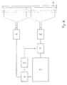
- a computing unit 1 which both the control of the device and the Evaluation of the measured values is used.
- To them are one Input unit 2 for entering commands, e.g. Legs Keyboard and an output unit 3 for the output of Results etc., e.g. B. a liquid crystal display, connected.
- a counter 4 the cycles of Output signal of an oscillator 5 counts, stands with Computing unit 1 in connection and also gives signals to one Transmitter 6 off.
- the oscillator 5 also controls an analog-to-digital converter 7, the downstream of a receiver 8 and also connected to an input of the computing unit 1 is.
- the oscillator 5 generates an electrical signal with a Frequency of 20 MHz in the example, i.e. a period of 50 ns.
- the counter 4 enters Signal to the transmitter 6 from the transmission of a short optical impulse caused by the same.
- the impulse is from one goal or from multiple goals that cut each part of the light cone, reflected and the reflections collected by the receiver 8 and into one electrical received signal e (Fig. 2 above) converted.
- the memory address is thereby each derived from the number n supplied by the counter 4, which is a measure of the sampling time, based on the signal, the transmission of the optical pulse by the transmitter 6 has triggered.
- a reference function r (FIG. 2 center) is used, which was determined in a manner which is explained in more detail below. Values of the reference function r are used at locations that follow one another at intervals of certain reference increments.
- the time interval is in each case a multiple m ⁇ of a basic interval corresponding here to the reference increment ⁇ .
- a similarity function is calculated directly as a measure of the similarity between the same and the received signal e.
- the time of reception can be determined more precisely in order to achieve a higher temporal resolution.
- the maxima are relatively far apart and the comparison functions do not overlap or only slightly overlap - i.e. the reflections on the various objectives do not or hardly overlap - the individual maxima are treated individually and the Correlation function f is interpolated by an interpolation function and then the time T k at which it reaches its maximum is determined as the exact time of reception.
- the expression can be generalized to continuous time variables.
- the reference function r is supplemented on the basis of base values to form a continuous function, ie a function that is defined over the entire interval [0, N ⁇ ] and can be differentiated as continuously as possible, preferably at least once. This can e.g. B. done by quadratic spline functions.
- the reference function r can be extended beyond the specified interval by setting it to zero there. Alternatively, an exponential decay can also be assumed.
- This mapping maps vectors in the image space of V ( T ) to their uniquely determined archetype in the complement of the nucleus of V ( T ), while it maps vectors in the complement of the image space to 0 .
- the minimum position of the non-linear function F ( T ) can be determined using known numerical methods. Examples are the method of steepest descent or the determination of a zero of the gradient of F by means of an iteration of linear approximations (Newton method). See also z. BE Stiefel: Introduction to Numerical Mathematics, Teubner Study Books Mathematics, BG Teubner 1976, p. 83f. However, methods with better convergence behavior are preferred, such as can be found in the following articles: DW Marquardt: An Algorithm for Least-Squares Estimation of Nonlinear Parameters, SIAM Journal on Applied Mathematics 11 (1963), 431-441 and K. Levenberg: A Method for the Solution of Certain Non-Linear Problems in Least Squares, Quarterly of Applied Mathematics 2 (1944), 164-168.
- the determination of the reference function can be different Wise. According to Fig. 3a it is by means of a comprising essential parts of the device according to FIG. 1 Construction made. It includes the computing unit 1, the Counter 4 and the oscillator 5 and the transmitter 6 and the Receiver 8 with the downstream A / D converter 7. Between the counter 4 and the transmitter 6 is a delay element 9 inserted. In addition, a reference target 10, z. Legs Blackboard provided at a certain distance from the Transmitter 6 and receiver 8 is set up.
- the counter After every 2,000 cycles of the oscillator 5, the counter gives 4 from a signal to the delay element 9, which it with certain delay to the transmitter 6 and the Transmission of an optical pulse triggers by the same.
- the optical pulse reflected at the reference target 10 is generated at the output of the receiver 8, a reference received signal that is sampled in the A / D converter 7 at intervals that the Correspond to sampling increment ⁇ .
- the base values determined in this way arrive at the computing unit 1 and are assigned to a specific sampling time, stored.
- the base values then follow one another at fixed intervals, which correspond to the reference increment ⁇ . If this is not the case, the values of the reference function r must be determined by interpolation at the positions corresponding to the integer multiples of the reference increment for use in (1).
- the procedure corresponds essentially to that which is used according to DE-A-42 33 196 when measuring the distance of a target. It is obvious that instead of the signal which triggers the transmission of an optical pulse by the transmitter 6, the reference reception signal can be delayed with the same effect.
- the reference function r also the results of several measurements taken one after the other are added or averaged are, similar to that according to DE-A-36 20 226 in Relation to measuring the distance of a target is described.
- the addition can be done digitally, it is however, it is also possible to measure the values in analog form, e.g. B. to store and add as electrical charges and first convert the sum into digital form, as in Similar context described in DE-A-44 40 613 is.
- Both methods namely the refinement of the time resolution and improving the signal-to-noise ratio as above for described the detection of the reference received signal can also be used in normal measuring operation either individually or together to improve Time resolution and the signal-to-noise ratio of the received signal e can be used if the fact that the The number of required impulses increased, no larger ones i has disadvantages. 1 is the device then add accordingly.
- FIG. 3 b Another possibility, shown in FIG. 3 b, for improving the temporal resolution of the reference received signal consists in changing the distance of the reference target 10.
- This also leads to delays in the received signal without the need for a delay element.
- the intensity of the received signal decreases approximately proportionally to the square of the distance of the reference target 10 due to the beam expansion.
- the delay values can be multiples of the reference increment, but can also assume other, non-equidistant values.
Landscapes
- Engineering & Computer Science (AREA)
- Physics & Mathematics (AREA)
- Computer Networks & Wireless Communication (AREA)
- General Physics & Mathematics (AREA)
- Radar, Positioning & Navigation (AREA)
- Remote Sensing (AREA)
- Electromagnetism (AREA)
- Optical Radar Systems And Details Thereof (AREA)
- Radar Systems Or Details Thereof (AREA)
- Measurement Of Optical Distance (AREA)
Priority Applications (7)
| Application Number | Priority Date | Filing Date | Title |
|---|---|---|---|
| EP99106840A EP1043603A1 (fr) | 1999-04-06 | 1999-04-06 | Méthode de détection de la distance d'au moins une cible |
| DE50001197T DE50001197D1 (de) | 1999-04-06 | 2000-04-04 | Verfahren zur Messung der Entfernung mindestens eines Ziels |
| AT00107292T ATE232306T1 (de) | 1999-04-06 | 2000-04-04 | Verfahren zur messung der entfernung mindestens eines ziels |
| US09/542,879 US6516286B1 (en) | 1999-04-06 | 2000-04-04 | Method for measuring the distance to at least one target |
| EP00107292A EP1043602B1 (fr) | 1999-04-06 | 2000-04-04 | Méthode de détection de la distance d'au moins une cible |
| CA2304083A CA2304083C (fr) | 1999-04-06 | 2000-04-05 | Methode de mesure de la distance d'au moins une cible |
| JP2000105448A JP4843128B2 (ja) | 1999-04-06 | 2000-04-06 | 少なくとも1つの目標物の距離測定方法 |
Applications Claiming Priority (2)
| Application Number | Priority Date | Filing Date | Title |
|---|---|---|---|
| EP99106840A EP1043603A1 (fr) | 1999-04-06 | 1999-04-06 | Méthode de détection de la distance d'au moins une cible |
| US09/542,879 US6516286B1 (en) | 1999-04-06 | 2000-04-04 | Method for measuring the distance to at least one target |
Publications (1)
| Publication Number | Publication Date |
|---|---|
| EP1043603A1 true EP1043603A1 (fr) | 2000-10-11 |
Family
ID=26152957
Family Applications (1)
| Application Number | Title | Priority Date | Filing Date |
|---|---|---|---|
| EP99106840A Withdrawn EP1043603A1 (fr) | 1999-04-06 | 1999-04-06 | Méthode de détection de la distance d'au moins une cible |
Country Status (5)
| Country | Link |
|---|---|
| EP (1) | EP1043603A1 (fr) |
| JP (1) | JP4843128B2 (fr) |
| AT (1) | ATE232306T1 (fr) |
| CA (1) | CA2304083C (fr) |
| DE (1) | DE50001197D1 (fr) |
Cited By (3)
| Publication number | Priority date | Publication date | Assignee | Title |
|---|---|---|---|---|
| EP3088914A4 (fr) * | 2013-12-27 | 2016-12-21 | Ricoh Co Ltd | Appareil de mesure de distance, appareil électronique, procédé de mesure de distance et programme de mesure de distance |
| WO2017025754A1 (fr) * | 2015-08-12 | 2017-02-16 | Trw Limited | Traitement d'un rayonnement reçu réfléchi par une cible |
| US11169255B2 (en) | 2016-12-08 | 2021-11-09 | Trw Limited | Processing a signal representative of at least one physical property of a physical system |
Families Citing this family (6)
| Publication number | Priority date | Publication date | Assignee | Title |
|---|---|---|---|---|
| JP2014174069A (ja) * | 2013-03-12 | 2014-09-22 | Mitsubishi Electric Corp | レーザ測距装置 |
| EP2789972B1 (fr) | 2013-04-12 | 2017-08-16 | Hexagon Technology Center GmbH | Appareil de mesure avec élément optique déformable |
| EP3502617B1 (fr) | 2017-12-21 | 2021-10-20 | Leica Geosystems AG | Dispositif de mesure à homogénéisation du faisceau de mesure |
| EP3783305B1 (fr) | 2019-08-21 | 2022-03-23 | Leica Geosystems AG | Système d'entraînement dans un instrument de mesure géodésique |
| EP3812701B1 (fr) | 2019-10-23 | 2022-08-24 | Hexagon Technology Center GmbH | Étalonnage de nivellement en ligne d'un instrument géodésique |
| EP4354084B1 (fr) | 2022-10-10 | 2026-05-20 | Hexagon Innovation Hub Gmbh | Étalonnage de mise à niveau sur le terrain d'un instrument d'arpentage |
Citations (5)
| Publication number | Priority date | Publication date | Assignee | Title |
|---|---|---|---|---|
| EP0312224A1 (fr) * | 1987-09-30 | 1989-04-19 | Panametrics, Inc. | Analysateur de la corrélation différentielle |
| EP0534056A1 (fr) * | 1991-08-28 | 1993-03-31 | Daimler-Benz Aerospace Aktiengesellschaft | Procédé et dispositif de mesure de la vitesse d'un objet mouvant utilisant au moins un détecteur de vitesse du type Radar-Doppler |
| DE19517001A1 (de) * | 1995-05-09 | 1996-11-14 | Sick Optik Elektronik Erwin | Verfahren und Vorrichtung zur Bestimmung der Lichtlaufzeit über eine zwischen einer Meßvorrichtung und einem reflektierenden Objekt angeordnete Meßstrecke |
| EP0797105A2 (fr) * | 1996-03-21 | 1997-09-24 | Siemens Aktiengesellschaft | Procédé pour la mesure du temp de trajet d'un signal électrique, électromagnétique, ou acoustique |
| EP0854368A2 (fr) * | 1997-01-20 | 1998-07-22 | Sick AG | Senseur luminex employant une évalution du temps de vol de lumière |
Family Cites Families (10)
| Publication number | Priority date | Publication date | Assignee | Title |
|---|---|---|---|---|
| JPS5480771A (en) * | 1977-12-10 | 1979-06-27 | Tech Res & Dev Inst Of Japan Def Agency | Range finder |
| JPS5846397A (ja) * | 1981-09-15 | 1983-03-17 | アンリツ株式会社 | 2信号の波形相似度測定装置 |
| JPS6252478A (ja) * | 1985-08-31 | 1987-03-07 | Nec Corp | 音響測深儀 |
| JPS641993A (en) * | 1987-06-23 | 1989-01-06 | Nec Corp | Echo sounder |
| JPS6443781A (en) * | 1987-08-11 | 1989-02-16 | Mitsubishi Electric Corp | Radar signal processor |
| JPH06100654B2 (ja) * | 1990-03-28 | 1994-12-12 | 運輸省港湾技術研究所長 | 超音波距離計 |
| JP3068674B2 (ja) * | 1991-07-29 | 2000-07-24 | 株式会社トキメック | 超音波送受波装置 |
| JPH05100022A (ja) * | 1991-10-11 | 1993-04-23 | Mitsubishi Heavy Ind Ltd | ソナー信号処理装置 |
| JPH05273272A (ja) * | 1992-01-16 | 1993-10-22 | Hamamatsu Photonics Kk | タイミング差測定システム |
| JP3641870B2 (ja) * | 1996-03-28 | 2005-04-27 | 日産自動車株式会社 | ランダム変調レーダ装置 |
-
1999
- 1999-04-06 EP EP99106840A patent/EP1043603A1/fr not_active Withdrawn
-
2000
- 2000-04-04 DE DE50001197T patent/DE50001197D1/de not_active Expired - Lifetime
- 2000-04-04 AT AT00107292T patent/ATE232306T1/de active
- 2000-04-05 CA CA2304083A patent/CA2304083C/fr not_active Expired - Lifetime
- 2000-04-06 JP JP2000105448A patent/JP4843128B2/ja not_active Expired - Lifetime
Patent Citations (5)
| Publication number | Priority date | Publication date | Assignee | Title |
|---|---|---|---|---|
| EP0312224A1 (fr) * | 1987-09-30 | 1989-04-19 | Panametrics, Inc. | Analysateur de la corrélation différentielle |
| EP0534056A1 (fr) * | 1991-08-28 | 1993-03-31 | Daimler-Benz Aerospace Aktiengesellschaft | Procédé et dispositif de mesure de la vitesse d'un objet mouvant utilisant au moins un détecteur de vitesse du type Radar-Doppler |
| DE19517001A1 (de) * | 1995-05-09 | 1996-11-14 | Sick Optik Elektronik Erwin | Verfahren und Vorrichtung zur Bestimmung der Lichtlaufzeit über eine zwischen einer Meßvorrichtung und einem reflektierenden Objekt angeordnete Meßstrecke |
| EP0797105A2 (fr) * | 1996-03-21 | 1997-09-24 | Siemens Aktiengesellschaft | Procédé pour la mesure du temp de trajet d'un signal électrique, électromagnétique, ou acoustique |
| EP0854368A2 (fr) * | 1997-01-20 | 1998-07-22 | Sick AG | Senseur luminex employant une évalution du temps de vol de lumière |
Cited By (5)
| Publication number | Priority date | Publication date | Assignee | Title |
|---|---|---|---|---|
| EP3088914A4 (fr) * | 2013-12-27 | 2016-12-21 | Ricoh Co Ltd | Appareil de mesure de distance, appareil électronique, procédé de mesure de distance et programme de mesure de distance |
| US10302747B2 (en) | 2013-12-27 | 2019-05-28 | Ricoh Company, Ltd. | Distance measuring apparatus, electronic device, method for measuring distance, and recording medium |
| WO2017025754A1 (fr) * | 2015-08-12 | 2017-02-16 | Trw Limited | Traitement d'un rayonnement reçu réfléchi par une cible |
| US10782391B2 (en) | 2015-08-12 | 2020-09-22 | Trw Limited | Processing received radiation reflected from a target |
| US11169255B2 (en) | 2016-12-08 | 2021-11-09 | Trw Limited | Processing a signal representative of at least one physical property of a physical system |
Also Published As
| Publication number | Publication date |
|---|---|
| ATE232306T1 (de) | 2003-02-15 |
| JP4843128B2 (ja) | 2011-12-21 |
| JP2000304862A (ja) | 2000-11-02 |
| DE50001197D1 (de) | 2003-03-13 |
| CA2304083C (fr) | 2013-05-28 |
| CA2304083A1 (fr) | 2000-10-06 |
Similar Documents
| Publication | Publication Date | Title |
|---|---|---|
| EP1043602B1 (fr) | Méthode de détection de la distance d'au moins une cible | |
| DE69429966T2 (de) | Entfernungsmessgerät mit Verwendung von Lichtimpulsen | |
| EP0677172B1 (fr) | Procede informatise faisant appel a un radar, pour mesurer les distances et les vitesses relatives entre un vehicule et des obstacles se trouvant en face de lui | |
| EP0797105B1 (fr) | Procédé pour la mesure du temp de trajet d'un signal électrique, électromagnétique, ou acoustique | |
| EP0533220B1 (fr) | Méthode pour distinguer au moins deux objectifs spécialement pour radars Doppler HPRF | |
| DE102006006572A1 (de) | Paarweise ZF-Abtastung für Puls-Laufzeit-Füllstandsensoren | |
| DE3789830T3 (de) | Radargerät zur Messung der Entfernung zu einer Oberfläche. | |
| DE69031747T2 (de) | Kompensierter Detektor für bewegte Ziele mit veränderlicher Wiederholungsfrequenz | |
| EP0128542B1 (fr) | Dispositif de radar Doppler à impulsions à fréquence de répétition d'impulsions variable | |
| DE3701786A1 (de) | Ultraschallgeschwindigkeitsmessvorrichtung | |
| DE69310004T2 (de) | Verfahren und Vorrichtung zur Feststellung des Erreichens eines vorausbestimmten Abstandes eines Punktreflektors mittels der Laufzeit einer kontinuierlichen Welle | |
| EP3467451B1 (fr) | Procédé et appareil de mesure de niveau de remplissage permettant de déterminer le niveau de remplissage d'un milieu au moyen d'une mesure radar continue | |
| EP2327966B1 (fr) | Mesure de distance d'une surface de séparation | |
| EP0786097B1 (fr) | Procede et dispositif de mesure electro-optique de distance | |
| WO2009129552A1 (fr) | Dispositif et procédé de mesure de l'instant de réception d'une impulsion | |
| EP0128543A1 (fr) | Dispositif de radar Doppler à impulsions à fréquence de répétition d'impulsions variable | |
| DE2309036B2 (de) | Impulsradarempfangsteil mit schwellenregelung | |
| DE2133497C3 (de) | Verfahren und Anordnung zur Korre lations Entfernungsmessung mittels einer pseudostochastischen Impulsfolge | |
| WO2007009833A1 (fr) | Procede et circuit permettant de determiner precisement une distance | |
| DE60122506T2 (de) | Nichtkohärenter integrator für signale mit hoher beschleunigungsunbestimmtheit | |
| DE19644791C2 (de) | Verfahren und Vorrichtung zur Bestimmung der Lichtlaufzeit über eine zwischen einer Meßvorrichtung und einem reflektierenden Objekt angeordnete Meßstrecke | |
| WO2001061287A1 (fr) | Procede et dispositif permettant de determiner le niveau de remplissage d'un produit dans un contenant | |
| DE102005044194A1 (de) | Messvorrichtung und Verfahren zum Messen von relativen Phasenlagen von digitalen Signalen | |
| DE68915199T2 (de) | Radar zum Korrigieren des Artillerieabfeuerns. | |
| EP1413896A2 (fr) | Procédé pour le fonctionnement d'un capteur radar et dispositif correspondant |
Legal Events
| Date | Code | Title | Description |
|---|---|---|---|
| PUAI | Public reference made under article 153(3) epc to a published international application that has entered the european phase |
Free format text: ORIGINAL CODE: 0009012 |
|
| AK | Designated contracting states |
Kind code of ref document: A1 Designated state(s): AT BE CH CY DE DK ES FI FR GB GR IE IT LI LU MC NL PT SE |
|
| AX | Request for extension of the european patent |
Free format text: AL;LT;LV;MK;RO;SI |
|
| AKX | Designation fees paid | ||
| STAA | Information on the status of an ep patent application or granted ep patent |
Free format text: STATUS: THE APPLICATION IS DEEMED TO BE WITHDRAWN |
|
| 18D | Application deemed to be withdrawn |
Effective date: 20010412 |
|
| REG | Reference to a national code |
Ref country code: DE Ref legal event code: 8566 |