EP1044909B1 - Vorrichtung und Verfahren zum Führen der offenen Kante einer Signatur während der Übergabe - Google Patents
Vorrichtung und Verfahren zum Führen der offenen Kante einer Signatur während der Übergabe Download PDFInfo
- Publication number
- EP1044909B1 EP1044909B1 EP00105377A EP00105377A EP1044909B1 EP 1044909 B1 EP1044909 B1 EP 1044909B1 EP 00105377 A EP00105377 A EP 00105377A EP 00105377 A EP00105377 A EP 00105377A EP 1044909 B1 EP1044909 B1 EP 1044909B1
- Authority
- EP
- European Patent Office
- Prior art keywords
- edge
- transfer device
- flat product
- circumferential surface
- gripper
- Prior art date
- Legal status (The legal status is an assumption and is not a legal conclusion. Google has not performed a legal analysis and makes no representation as to the accuracy of the status listed.)
- Expired - Lifetime
Links
Images


Classifications
-
- B—PERFORMING OPERATIONS; TRANSPORTING
- B65—CONVEYING; PACKING; STORING; HANDLING THIN OR FILAMENTARY MATERIAL
- B65H—HANDLING THIN OR FILAMENTARY MATERIAL, e.g. SHEETS, WEBS, CABLES
- B65H29/00—Delivering or advancing articles from machines; Advancing articles to or into piles
- B65H29/02—Delivering or advancing articles from machines; Advancing articles to or into piles by mechanical grippers engaging the leading edge only of the articles
- B65H29/06—Delivering or advancing articles from machines; Advancing articles to or into piles by mechanical grippers engaging the leading edge only of the articles the grippers being carried by rotating members
-
- B—PERFORMING OPERATIONS; TRANSPORTING
- B65—CONVEYING; PACKING; STORING; HANDLING THIN OR FILAMENTARY MATERIAL
- B65H—HANDLING THIN OR FILAMENTARY MATERIAL, e.g. SHEETS, WEBS, CABLES
- B65H29/00—Delivering or advancing articles from machines; Advancing articles to or into piles
- B65H29/52—Stationary guides or smoothers
-
- B—PERFORMING OPERATIONS; TRANSPORTING
- B65—CONVEYING; PACKING; STORING; HANDLING THIN OR FILAMENTARY MATERIAL
- B65H—HANDLING THIN OR FILAMENTARY MATERIAL, e.g. SHEETS, WEBS, CABLES
- B65H2301/00—Handling processes for sheets or webs
- B65H2301/40—Type of handling process
- B65H2301/44—Moving, forwarding, guiding material
- B65H2301/447—Moving, forwarding, guiding material transferring material between transport devices
- B65H2301/4473—Belts, endless moving elements on which the material is in surface contact
-
- B—PERFORMING OPERATIONS; TRANSPORTING
- B65—CONVEYING; PACKING; STORING; HANDLING THIN OR FILAMENTARY MATERIAL
- B65H—HANDLING THIN OR FILAMENTARY MATERIAL, e.g. SHEETS, WEBS, CABLES
- B65H2301/00—Handling processes for sheets or webs
- B65H2301/40—Type of handling process
- B65H2301/44—Moving, forwarding, guiding material
- B65H2301/447—Moving, forwarding, guiding material transferring material between transport devices
- B65H2301/4474—Pair of cooperating moving elements as rollers, belts forming nip into which material is transported
Definitions
- the present invention relates to an apparatus and a method for guiding a Edge of a signature in a printing press, in particular a device and a Method for preventing kinking in the open edge of a press in a printing machine folded signature when passing the signature to another section of the Press.
- z. B offset printing machines in which material webs are printed, The printed web is cut into signatures, which are then folded.
- a Signature is a portion of a web cut by a web once or folded several times.
- a folded signature S is shown, which is a folded edge F and an open edge O has.
- the folded signatures S are collected and to a finished printed product, e.g. As a journal bound.
- the folded signatures are usually by means of tape devices from the folding and Carved out cutting devices.
- Fig. 4 is a cross-sectional and side view, respectively and
- FIG. 5 is a partial perspective view of a printing machine of the prior art, in FIG a folded signature S by means of a tape device T in a direction D from a Cutting and folding device M is conveyed out.
- the tape device T comprises a Band or multiple bands B moving continuously in one direction d Capture at least one side of the folded signatures S and this rectilinear transport.
- One of the bands B of the tape device T usually overlaps the open one Edge O of the folded signatures S and is wide enough to ensure that too Variations in the width W of the folded signatures S the open edge O of the folded Signature S is always overlapped by the band B. By this arrangement is ensure that the open edge O is held down by the band B, so that the Corners C of the open edges O can not be folded over.
- the belt device T shown in Fig. 4 of a device of the prior art transfers the folded signatures S to the transfer device 101, for example rotates in a direction R1 and comprises a device by means of which the signature S on its outer surface is held.
- the signature S shown in FIG Band device T passed to the outer surface of the transfer device 101 and is after the uncontrolled passing of a gap G at its front edge I of one out the (indicated by the dashed line) periphery of a in direction R2 rotating brake drum 6 emergent gripper mechanism 4, 5 taken.
- a disadvantage of the known devices shown in FIGS. 4 and 5 for the transfer of folded signatures is that the corners C of the open edge O of the folded Signatures S during the transfer from the belt device T to the brake drum 6, from the tape device T to the transfer device 101 or from the Transfer device 101 to another transfer device, eg. B. a subordinate Brake drum, often undesirable kinking, as dashed lines in FIG. 6 drawn corner C 'is shown.
- the web passes a folder and is folded once or several times.
- the folded web by applying an electrical voltage electrostatically charged and cut into folded signatures S Due to the electrostatic charging of the folded signatures S pull the sides of the signature S and thus also the open edges O on each other and adhere to each other, causing the open edge O thicker and thus the risk of kinking the open edge O. is reduced.
- a disadvantage of the electrostatic charge to prevent buckling is that the subsequent processing of the signatures S is made more difficult. If z. B. a number folded signatures S then collected into a magazine and stapled to be opened, the open edges O of each folded signature S must be opened, so that another folded signature can be inserted. Which by the electrostatic However, charge-induced attraction at the open edge O impairs this Opening and inserting signatures S. In addition, the electrostatic charge despite the increased stiffness of the open edge O due to the electrostatic Attraction not reliable enough to complete a kinking of the corners C. prevent.
- document EP 0725025 A2 already discloses a sheet guiding device for Printing presses known in which the sheet from a first rotating drum a second rotating drum, which is equipped with grippers, are passed.
- the second rotating drum is a guide device, which spaced is arranged to the surface of the rotating drum assigned.
- the grippers of second rotating drum move in between the surface of the second rotating drum and the surface of the guide means formed gap.
- the Kinking of the corners C of the open edges O folded signatures S without electrostatic Prevents charging is accordingly that subsequent Processing operations of the folded signatures are not affected.
- the device according to the invention comprises, for example, one between a Belt device, arranged a deflection cylinder and / or a brake drum Guide mechanism, preferably at the front edge of the to be handed over Signatures facing side is arranged. Other places may also have additional Guiding mechanisms may be provided.
- the guide mechanism is preferably wide enough to handle folded signatures of different widths.
- the guide mechanism preferably includes a plurality of over its entire Wide slits arranged wide.
- the gripper devices include preferably in the region of the guide mechanism a plurality of preferably also about her across the width arranged narrow fingers. These slender fingers of the Gripper mechanisms are designed in such a way that they pass through the narrow slots of the guide mechanism can run.
- the guide mechanism is in the way designed to prevent the movement of the open edge of the folded signatures of the Transfer mechanism controls over gaps between transfer mechanisms and in this way a folding of the open edges of the folded signatures in the Handover prevented.
- Steps out Providing a variety of slots in the guide mechanism, and holding of the flat product on the peripheral surface by a plurality of fingers of a Gripper, which pass through the slots of the guide mechanism like a comb.
- folded signatures of a Transfer mechanism to at least in the area of preferably open Passed edges of the folded signatures arranged guide mechanism.
- the Guide mechanism preferably comprises a plurality of preferably over its across narrow width slits arranged along the entire width Guide mechanism run.
- a transfer gripper with a variety of narrow ones Fingers capture the folded signature before moving out of one end of the guide mechanism emerges.
- the narrow fingers of the transfer mechanism run through the narrow Slits in the guide mechanism, allowing for signature grabbing, before it comes out of the end of the guide mechanism.
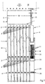
- Fig. 1 shows a plan view of a folded signature S, of a cutting and Folding mechanism M away in a direction D to a deflection cylinder 1 is conveyed.
- the folded signature S has a folded edge F, an open edge O, a leading edge I and a trailing edge t. Due to during the cutting or folding in the Cutting and folding mechanism M possibly occurring inaccuracies can Signatures S have a different width W. These differences in width will be v represented by the hatched in Fig. 1 drawn area.
- the signature S After the signature S has passed the cutting and folding mechanism M, it is from a belt device T with at least one band B on.
- the band B is in Fig. 1 only partially shown.
- the band B is aligned along the open edge O of the folded signature S and has one Width on that the open edge O of the signatures S independently of the Width difference v in each case is contacted by the band B. This will be the open edge O held down by the band B, so that during transport of the Signature S by the band B no kinking of the edges can occur.
- the tape T transfers the folded signature S to the one rotating in a direction R1 Deflection cylinder 1, at its peripheral surface leading edge gripper 2 and Rear edge gripper 3 are arranged.
- FIGS. 1 and 2 FIGS Leading edge gripper 2 and trailing edge gripper 3 a plurality of gripper fingers 2 ', 3', the in along the peripheral surface of the deflection cylinder 1 extending slots. 7 are arranged.
- the leading edge gripper 2 and trailing edge gripper 3 are pivotally attached arranged the deflection cylinder 1, so that they are pivoted to the deflection cylinder 1 can be so that alternately a leading edge I and a trailing edge t one of the tape device T transported folded signature S can be detected.
- the finger 2 'or 3' together with the guide mechanism 20 described below the possible changes in the width W of a folded signature S bill so that products of various standard widths can be handled.
- the closed edge C of the signatures S is preferably along the width of the Deflection cylinder 1 positioned so that it is in the vicinity of one of the fingers 2 'or 3' while the open edge O is preferably positioned to extend is located below the guide mechanism 20. In this way, the edges C, O regardless of the width W of the folded signatures S or the width difference v ideally run.
- an inventive guide mechanism 20 is arranged above one of the open edge O of the signatures S side 25 facing the Deflection cylinder 1, an inventive guide mechanism 20 is arranged.
- the guide mechanism 20 is preferably on one end to the pulley of the belt B of the belt device T arranged.
- the pulley of the belt B of the belt device T in one end of the Guide mechanism 20 may be stored.
- it includes Guide mechanism 20 a plurality of arranged over its entire width and along the direction of rotation R1 of the deflection cylinder 1 extending narrow slots 21st
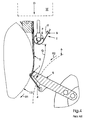
- the lower surface 26 of the guide mechanism 20 preferably adjoins the Circumferential surface of the deflection cylinder 1 and follows its contour. Through this Arrangement of the lower surface 26 ensures that the open edge O of the signatures S between the peripheral surface of the Umlenkzylinders 1 and the lower surface 26 of the Guide mechanism 20 is guided securely, so that a folding of the edge O of folded signature S is prevented.
- the width w of the guide mechanism 20 is preferably selected such that Variations v in the width W of the folded signatures S are handled easily can, d. H. that the guide mechanism 20 always over the open edge of the O folded signature S, even if the width W of the signatures S fluctuates.
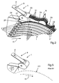
- the portion of the leading edge gripper 2 and the trailing edge gripper 3, to which the open edge O facing side 25 of the deflection cylinder 1 adjacent to the open Side of the signatures is arranged as a variety or series of narrow fingers or micro-fingers 22 formed.
- the fingers 22 are preferably in the way arranged to be aligned by associated, along the fingers 22 aligned Slots or micro-slots 21 of the guide mechanism 20 can pass, when the deflection cylinder 1 rotates in the direction R1.
- the narrow fingers or micro-fingers 22 are here preferably in the region of the open edge O of the folded signatures S arranged. In this way affects the function of the leading edge gripper 2 and the Rear edge gripper 3, the guide mechanism 20 is not when the leading edge gripper. 2 and the trailing edge grippers 3, the leading edge I or the trailing edge t of the Tape device T leaving folded signatures S take.
- a further arranged lower guide member 24 which also has narrow slots 27 through the plurality of narrow fingers 22 upon rotation of the deflection cylinder 1 in the Can pass direction R1.
- This lower guide element 24 serves as Support for the underside of a folded signature S in the tape device T before the folded signature contacts the peripheral surface of the deflection cylinder 1.
- the variety of narrow fingers 22 preferably forms part of the leading edge grippers 2 and Schukantengreifer 3 and is pivotable together with the fingers 2 'or 3', the Detecting and releasing the leading edge I or trailing edge t of a folded signature S a Perform pivoting movement.
- the guide mechanism 20 preferably further extends as to the point where the brake drum 6, the leading edge I of the folded signature S recorded. This ensures that the folded signature S along its entire Transport path from the tape device T to the brake drum 6 securely between the Guide mechanism 20 and the deflection cylinder 1 is guided.
- the side of the edge gripping mechanism 4, 5 of the brake drum 6 for Avoiding interactions between the edge gripping mechanism 4, 5 and the Guide mechanism 20 narrow fingers 28 at the open edge O of the signatures S facing side 25 of the Umlenkzylinders 1. These narrow fingers 28 are like the narrow finger 22 of the guide mechanism 20 provided with narrow slots 27 and run upon rotation of the brake drum 6 in the direction R2 along this.
- a signature e.g. B. a folded Signature S
- a transport device for. B. a belt device T transported.
- the signature is sent to a transfer device, e.g. B. a deflection cylinder 1 or a Brake drum 6, passed.
- a transfer device e.g. B. a deflection cylinder 1 or a Brake drum 6, passed.
- Gripper mechanisms eg. Narrow (Gripper) Fingers or micro-fingers 22, 28, run through narrow slots or micro-slots 21 on the guide mechanism and engage the leading edge I or Trailing t of the guided by the guide mechanism 20 signature before this Guide mechanism 20 leaves.
- the guide mechanism 20 is preferably made of a material that is not Increased paper jam risk does not or does not cause total failure of the entire system Device performs when one of the narrow fingers 22, 28 bends so that he does not more along the narrow slots 21 runs.
- the guide mechanism 20 may, for. B. off a resilient or flexible material, such. As rubber or plastic be, which also be designed as a brush with narrow slots or may consist of a foam or similar resilient or flexible material.
- the present invention may also be used to guide any other edge of a Signature or a non-folded sheet or other flexible product and in be used any transfer device.
Landscapes
- Engineering & Computer Science (AREA)
- Mechanical Engineering (AREA)
- Feeding Of Articles By Means Other Than Belts Or Rollers (AREA)
- Folding Of Thin Sheet-Like Materials, Special Discharging Devices, And Others (AREA)
- Preliminary Treatment Of Fibers (AREA)
- Labeling Devices (AREA)
- Position Fixing By Use Of Radio Waves (AREA)
Description
- Fig. 1
- eine schematische Draufsicht einer Übergabevorrichtung mit einem erfindungsgemäßen Führungsmechanismus;
- Fig. 2
- eine perspektivische Teilansicht der erfindungsgemäßen Vorrichtung;
- Fig. 3
- eine teilweise Querschnittsansicht bzw. Seitenansicht der erfindungsgemäßen Vorrichtung;
- Fig. 4
- eine teilweise Querschnittsansicht bzw. Seitenansicht einer Übergabevorrichtung des Standes der Technik;
- Fig. 5
- eine perspektivische Teilansicht eines Übergabemechanismus des Standes der Technik;
- Fig. 6
- eine perspektivische Darstellung einer gefalzten Signatur nach dem Stand der Technik.
- B
- Band
- C
- Ecke
- C'
- umgeknickte Ecke
- D
- Transportrichtung
- d
- Bewegungsrichtung der Bänder
- F
- Falzkante
- I
- Vorderkante
- M
- Schneide- und Falzvorrichtung
- O
- offene Kante
- S
- Signatur
- T
- Bandvorrichtung
- t
- Hinterkante
- v
- Breitenschwankung
- W
- Signaturenbreite
- R1
- Drehrichtung des Umlenkzylinders
- R2
- Drehrichtung der Bremstrommel
- 1
- Umlenkzylinder
- 2
- Vorderkantengreifer
- 2'
- Finger
- 3
- Hinterkantengreifer
- 3'
- Finger
- 4
- Vorderkantengreifmechanismus
- 5
- Vorderkantengreifmechanismus
- 6
- Bremstrommel
- 7
- Schlitz
- 20
- Führungsmechanismus
- 21
- schmale Schlitze
- 22
- schinale Finger
- 24
- unteres Führungselement
- 25
- der offenen Kante der Signaturen zugewandte Seite des Umlenkzylinders
- 26
- untere Fläche
- 27
- schmale Schlitze
- 28
- schmale Finger
- 101
- Übergabevorrichtung
Claims (13)
- Vorrichtung zum Führen einer Kante (C, O) eines flachen Produkts (S) während der Übergabe des flachen Produkts (S) mit einer Übergabevorrichtung (1), auf deren Umfangsoberfläche das flache Produkt (S) übergeben wird, wobei die Übergabevorrichtung (1) mindestens einen Greifer (2, 3) umfasst, und mit einem Führungsmechanismus (20), der nahe der Umfangsoberfläche der Übergabevorrichtung (1) die Kante (C, O) des flachen Produkts (S) überlappend angeordnet ist,
dadurch gekennzeichnet, dass der Führungsmechanismus (20) mindestens einen schmalen Schlitz (21) umfasst, und
dass der mindestens eine Greifer (2, 3) mindestens einen dem schmalen Schlitz (21) zugeordneten Finger (22, 28) umfasst, der auf den schmalen Schlitz (21) ausgerichtet ist und in diesem entlang läuft. - Vorrichtung nach Anspruch 1,
dadurch gekennzeichnet, dass der Führungsmechanismus (20) eine Vielzahl von Schlitzen (21) umfasst, und dass der mindestens eine Greifer (2, 3) eine Vielzahl von Fingern (22, 28) umfasst, die auf die Vielzahl von Schlitzen (21) ausgerichtet sind und in diesen entlang laufen. - Vorrichtung nach einem der vorhergehenden Ansprüche,
dadurch gekennzeichnet, dass die Übergabevorrichtung (1) ein Zylinder ist. - Vorrichtung nach einem der vorhergehenden Ansprüche,
dadurch gekennzeichnet, dass die Übergabevorrichtung (1) eine Vielzahl von entlang ihres Umfangs angeordneten, weiteren schlitzlosen Greifern (2, 3) umfasst. - Vorrichtung nach einem der vorhergehenden Ansprüche,
dadurch gekennzeichnet, dass eine Transportvorrichtung (T) zur Übergabe der flachen Produkte (S) an die Übergabevorrichtung (1) vorgesehen ist, welche ein die flachen Produkte (S) im Bereich der Kante (C, O) überlappendes Band (B) umfasst. - Vorrichtung nach einem der Ansprüche 2 bis 5,
dadurch gekennzeichnet, dass der Führungsmechanismus (20) auf der dem Zylinder (1) zugewandten Seite eine der Form des Zylinders (1) angepasste Kontur aufweist. - Vorrichtung nach einem der Ansprüche 2 bis 6,
dadurch gekennzeichnet, dass der Zylinder (1) ein Umlenkzylinder ist, der eine Vielzahl von weiteren Vorderkantengreifern (2) und Hinterkantengreifern (3) umfasst, welche die flachen Produkte (S) an ihren Vorderkanten und/oder Hinterkanten ergreifen. - Vorrichtung nach einem der Ansprüche 2 bis 7,
dadurch gekennzeichnet, dass weiterhin eine Bremstrommel (6) vorgesehen ist, die die auf der Umfangsoberfläche des Zylinders (1) geführten flachen Produkte (S) übernimmt. - Verfahren zum Führen einer Kante eines flachen Produkts (S) in einem Falzapparat einer Rotationsdruckmaschine
mit den Schritten:gekennzeichnet durchZuführen des flachen Produkts (S) zu einer Übergabevorrichtung (1);Übergeben des flachen Produkts (S) an eine Umfangsoberfläche der Übergabevorrichtung (1);Führen des flachen Produkts (S) zwischen der Umfangsoberfläche der Übergabevorrichtung (1) und einem Führungsmechanismus (20), der nahe der Umfangsoberfläche der Übergabevorrichtung (1) die Kante (C, O) des flachen Produkts (S) überlappend angeordnet ist,
die folgenden Schritte:Vorsehen einer Vielzahl von Schlitzen (21) im Führungsmechanismus (20), undHalten des flachen Produkts (S) auf der Umfangsoberfläche durch eine Vielzahl von Fingern (22, 28) eines Greifers (2, 3), welche durch die Schlitze (21) des Führungsmechanismus (20) kammartig hindurchtreten. - Verfahren nach Anspruch 9,
dadurch gekennzeichnet, dass die Umfangsoberfläche die Umfangsoberfläche eines Zylinders (1) des Falzapparates ist. - Verfahren nach einem der Ansprüche 9 oder 10,
dadurch gekennzeichnet, dass die Finger (22, 28) das flache Produkt (S) ergreifen, während dieses zwischen der Umfangsoberfläche der Übergabevorrichtung (1) und dem Führungsmechanismus (20) geführt wird. - Verfahren nach einem der Ansprüche 9 bis 11,
dadurch gekennzeichnet, dass die Zufuhr des flachen Produkts (S) zur Übergabevorrichtung (1) mit Hilfe von mindestens einem Band (B) erfolgt, welches eine Kante (C, O) des flachen Produkts (S) überlappend angeordnet ist. - Falzapparat einer Rotationsdruckmaschine,
gekennzeichnet durch
eine Vorrichtung nach einem der Ansprüche 1 bis 8 zum Führen einer insbesondere offenen Kante (C, O) einer insbesondere gefalzten Signatur (S).
Applications Claiming Priority (2)
| Application Number | Priority Date | Filing Date | Title |
|---|---|---|---|
| US286894 | 1999-04-06 | ||
| US09/286,894 US6186489B1 (en) | 1999-04-06 | 1999-04-06 | Method and apparatus for constraining the open edge of a signature during transfer |
Publications (3)
| Publication Number | Publication Date |
|---|---|
| EP1044909A2 EP1044909A2 (de) | 2000-10-18 |
| EP1044909A3 EP1044909A3 (de) | 2002-12-18 |
| EP1044909B1 true EP1044909B1 (de) | 2005-03-09 |
Family
ID=23100625
Family Applications (1)
| Application Number | Title | Priority Date | Filing Date |
|---|---|---|---|
| EP00105377A Expired - Lifetime EP1044909B1 (de) | 1999-04-06 | 2000-03-20 | Vorrichtung und Verfahren zum Führen der offenen Kante einer Signatur während der Übergabe |
Country Status (5)
| Country | Link |
|---|---|
| US (2) | US6186489B1 (de) |
| EP (1) | EP1044909B1 (de) |
| JP (1) | JP4495298B2 (de) |
| AT (1) | ATE290503T1 (de) |
| DE (1) | DE50009690D1 (de) |
Families Citing this family (2)
| Publication number | Priority date | Publication date | Assignee | Title |
|---|---|---|---|---|
| DE19735051C2 (de) * | 1997-08-13 | 1999-06-17 | Koenig & Bauer Ag | Vorrichtung zum Aufteilen eines Stromes von Signaturen |
| US20080048378A1 (en) * | 2006-08-18 | 2008-02-28 | Goss International Americas, Inc. | Gathering device with book comb |
Family Cites Families (12)
| Publication number | Priority date | Publication date | Assignee | Title |
|---|---|---|---|---|
| DE2460503C3 (de) * | 1974-12-20 | 1979-05-03 | Heidelberger Druckmaschinen Ag, 6900 Heidelberg | Umstell- und Einstellvorrichtung einer Übergabetrommel zur Bogenüberführung |
| US4815870A (en) * | 1987-10-22 | 1989-03-28 | Eastman Kodak Company | Receiver clamping arrangement for thermal printers |
| US4943045A (en) * | 1988-08-15 | 1990-07-24 | Tektronix, Inc. | Printer sheet feed system |
| DE3934217A1 (de) * | 1989-10-13 | 1991-04-25 | Widmann Karl Schweissmasch | Vorrichtung zum anbringen von verstaerkungen an registereinlagen |
| US5141221A (en) * | 1990-11-05 | 1992-08-25 | Heidelberg Harris Gmbh | Deceleration device in the folder of a rotary printing machine |
| DE4103296C1 (de) * | 1991-02-04 | 1992-04-23 | Heidelberger Druckmaschinen Ag, 6900 Heidelberg, De | |
| JP3434855B2 (ja) * | 1992-09-02 | 2003-08-11 | グラプハ−ホルディング・アクチエンゲゼルシヤフト | 印刷物を周期的に送るための装置 |
| US5265858A (en) * | 1992-11-02 | 1993-11-30 | Am International, Inc. | Apparatus for converting a sheet material feeder from on edge to bottom feed |
| DE19549589B4 (de) * | 1995-02-01 | 2005-11-17 | Heidelberger Druckmaschinen Ag | Bogenleiteinrichtung für Druckmaschinen |
| US5904351A (en) * | 1995-09-25 | 1999-05-18 | Sterling Dry Imaging Systems, Inc. | Method and apparatus for desensitizing print media on a print drum to the effects of debris contamination and air turbulence |
| US5832872A (en) * | 1997-05-23 | 1998-11-10 | Pearce; Woodrow W. | Animal feeding bowl |
| JP3757590B2 (ja) * | 1997-12-19 | 2006-03-22 | コニカミノルタホールディングス株式会社 | 紙搬送装置及び紙搬送方法 |
-
1999
- 1999-04-06 US US09/286,894 patent/US6186489B1/en not_active Expired - Fee Related
-
2000
- 2000-03-20 DE DE50009690T patent/DE50009690D1/de not_active Expired - Lifetime
- 2000-03-20 AT AT00105377T patent/ATE290503T1/de not_active IP Right Cessation
- 2000-03-20 EP EP00105377A patent/EP1044909B1/de not_active Expired - Lifetime
- 2000-04-06 JP JP2000105297A patent/JP4495298B2/ja not_active Expired - Fee Related
- 2000-12-14 US US09/736,622 patent/US6347793B2/en not_active Expired - Lifetime
Also Published As
| Publication number | Publication date |
|---|---|
| DE50009690D1 (de) | 2005-04-14 |
| JP4495298B2 (ja) | 2010-06-30 |
| EP1044909A3 (de) | 2002-12-18 |
| US6347793B2 (en) | 2002-02-19 |
| JP2000309177A (ja) | 2000-11-07 |
| ATE290503T1 (de) | 2005-03-15 |
| EP1044909A2 (de) | 2000-10-18 |
| US20010016136A1 (en) | 2001-08-23 |
| US6186489B1 (en) | 2001-02-13 |
Similar Documents
| Publication | Publication Date | Title |
|---|---|---|
| EP0827931B1 (de) | Vorrichtung und Verfahren zum dynamischen Führen von flachen produkten | |
| DE69106464T2 (de) | Einrichtung zum öffnen von gefalteten Druckereierzeugnissen. | |
| DE2647265C2 (de) | Zuführvorrichtung für ein Fotokopiergerät | |
| DE19503110A1 (de) | Bogenleiteinrichtung für Druckmaschinen | |
| CH649972A5 (de) | Vorrichtung zum uebereinanderlegen von einzelnen flaechigen erzeugnissen, insbesondere druckprodukten. | |
| DE69623392T2 (de) | Sammeleinheit für einen Dokumentensatz und Ausgabesystem | |
| EP0250771B1 (de) | Vorrichtung zur Entnahme von Bogen- oder Falzexemplaren von einem Falzklappenzylinder | |
| DE2731575B2 (de) | Verfahren und Anordnung zum wahlweisen seitlichen Verschieben von in einer vorgegebenen Richtung zu fördernden Blättern | |
| EP0250758B1 (de) | Falz- und Transportvorrichtung | |
| DE19940535A1 (de) | Vorrichtung zum Umlenken von Signaturen | |
| DE10020316A1 (de) | Zylinderanordnung für einen Falzapparat einer Rotationsdruckmaschine | |
| DE2626264A1 (de) | Vorrichtung zum zufuehren und auffaechern von papierblaettern | |
| EP1097892B1 (de) | Vorrichtung und Verfahren zum Schneiden und Umlenken von Signaturen | |
| DE69125504T2 (de) | Bogenzuführvorrichtung | |
| EP1120374A2 (de) | Schaltbares Produktgreiferelement in einem Falzapparat | |
| DE102020105126A1 (de) | Bogentransportvorrichtung mit einer elastisch verformbaren Trägerfläche zum Übertragen von Bögen zwischen zwei Förderern in einem Drucksystem | |
| EP1112952B1 (de) | Vorrichtung zum fortlaufenden Falzen von flachem Material | |
| EP1108672B1 (de) | Verfahren und Vorrichtung zum linearen Falzen | |
| EP1044909A2 (de) | Vorrichtung und Verfahren zum Führen der offenen Kante einer Signatur während der Übergabe | |
| EP1110894B1 (de) | Verfahren und Vorrichtung zum Falzen von Materialbogen | |
| DE19713361A1 (de) | Verfahren und Vorrichtung zum abschmierfreien Führen eines bedruckten Bogens auf einem bogenführenden Zylinder einer Druckmaschine, insbesondere auf einer Wendetrommel einer Bogenrotations-Offsetdruckmaschine im Schöndruckbetrieb | |
| EP1207128B1 (de) | Falzapparat mit einer Führungseinrichtung | |
| EP0462372B1 (de) | Falzapparat für eine Rollenrotationsdruckmaschine | |
| EP0953534B1 (de) | System zum angepassten Zuführen eines geschuppten Stromes bogenförmiger Produkte | |
| DE3149226C2 (de) | Transportvorrichtung für Signaturbögen, Lagen o.ä. |
Legal Events
| Date | Code | Title | Description |
|---|---|---|---|
| PUAI | Public reference made under article 153(3) epc to a published international application that has entered the european phase |
Free format text: ORIGINAL CODE: 0009012 |
|
| AK | Designated contracting states |
Kind code of ref document: A2 Designated state(s): AT BE CH CY DE DK ES FI FR GB GR IE IT LI LU MC NL PT SE |
|
| AX | Request for extension of the european patent |
Free format text: AL;LT;LV;MK;RO;SI |
|
| PUAL | Search report despatched |
Free format text: ORIGINAL CODE: 0009013 |
|
| AK | Designated contracting states |
Kind code of ref document: A3 Designated state(s): AT BE CH CY DE DK ES FI FR GB GR IE IT LI LU MC NL PT SE |
|
| AX | Request for extension of the european patent |
Free format text: AL;LT;LV;MK;RO;SI |
|
| 17P | Request for examination filed |
Effective date: 20021125 |
|
| 17Q | First examination report despatched |
Effective date: 20030331 |
|
| AKX | Designation fees paid |
Designated state(s): AT BE CH CY DE DK ES FI FR GB GR IE IT LI LU MC NL PT SE |
|
| GRAP | Despatch of communication of intention to grant a patent |
Free format text: ORIGINAL CODE: EPIDOSNIGR1 |
|
| RAP1 | Party data changed (applicant data changed or rights of an application transferred) |
Owner name: GOSS INTERNATIONAL AMERICAS, INC. |
|
| GRAS | Grant fee paid |
Free format text: ORIGINAL CODE: EPIDOSNIGR3 |
|
| GRAA | (expected) grant |
Free format text: ORIGINAL CODE: 0009210 |
|
| AK | Designated contracting states |
Kind code of ref document: B1 Designated state(s): AT BE CH CY DE DK ES FI FR GB GR IE IT LI LU MC NL PT SE |
|
| PG25 | Lapsed in a contracting state [announced via postgrant information from national office to epo] |
Ref country code: FI Free format text: LAPSE BECAUSE OF FAILURE TO SUBMIT A TRANSLATION OF THE DESCRIPTION OR TO PAY THE FEE WITHIN THE PRESCRIBED TIME-LIMIT Effective date: 20050309 Ref country code: IE Free format text: LAPSE BECAUSE OF FAILURE TO SUBMIT A TRANSLATION OF THE DESCRIPTION OR TO PAY THE FEE WITHIN THE PRESCRIBED TIME-LIMIT Effective date: 20050309 Ref country code: NL Free format text: LAPSE BECAUSE OF FAILURE TO SUBMIT A TRANSLATION OF THE DESCRIPTION OR TO PAY THE FEE WITHIN THE PRESCRIBED TIME-LIMIT Effective date: 20050309 Ref country code: IT Free format text: LAPSE BECAUSE OF FAILURE TO SUBMIT A TRANSLATION OF THE DESCRIPTION OR TO PAY THE FEE WITHIN THE PRESCRIBED TIME-LIMIT;WARNING: LAPSES OF ITALIAN PATENTS WITH EFFECTIVE DATE BEFORE 2007 MAY HAVE OCCURRED AT ANY TIME BEFORE 2007. THE CORRECT EFFECTIVE DATE MAY BE DIFFERENT FROM THE ONE RECORDED. Effective date: 20050309 |
|
| REG | Reference to a national code |
Ref country code: GB Ref legal event code: FG4D Free format text: NOT ENGLISH |
|
| REG | Reference to a national code |
Ref country code: CH Ref legal event code: EP |
|
| PG25 | Lapsed in a contracting state [announced via postgrant information from national office to epo] |
Ref country code: LU Free format text: LAPSE BECAUSE OF NON-PAYMENT OF DUE FEES Effective date: 20050320 Ref country code: CY Free format text: LAPSE BECAUSE OF FAILURE TO SUBMIT A TRANSLATION OF THE DESCRIPTION OR TO PAY THE FEE WITHIN THE PRESCRIBED TIME-LIMIT Effective date: 20050320 Ref country code: AT Free format text: LAPSE BECAUSE OF NON-PAYMENT OF DUE FEES Effective date: 20050320 |
|
| PG25 | Lapsed in a contracting state [announced via postgrant information from national office to epo] |
Ref country code: BE Free format text: LAPSE BECAUSE OF NON-PAYMENT OF DUE FEES Effective date: 20050331 Ref country code: MC Free format text: LAPSE BECAUSE OF NON-PAYMENT OF DUE FEES Effective date: 20050331 |
|
| REG | Reference to a national code |
Ref country code: IE Ref legal event code: FG4D Free format text: GERMAN |
|
| REF | Corresponds to: |
Ref document number: 50009690 Country of ref document: DE Date of ref document: 20050414 Kind code of ref document: P |
|
| GBT | Gb: translation of ep patent filed (gb section 77(6)(a)/1977) |
Effective date: 20050404 |
|
| PG25 | Lapsed in a contracting state [announced via postgrant information from national office to epo] |
Ref country code: DK Free format text: LAPSE BECAUSE OF FAILURE TO SUBMIT A TRANSLATION OF THE DESCRIPTION OR TO PAY THE FEE WITHIN THE PRESCRIBED TIME-LIMIT Effective date: 20050609 Ref country code: GR Free format text: LAPSE BECAUSE OF FAILURE TO SUBMIT A TRANSLATION OF THE DESCRIPTION OR TO PAY THE FEE WITHIN THE PRESCRIBED TIME-LIMIT Effective date: 20050609 |
|
| PG25 | Lapsed in a contracting state [announced via postgrant information from national office to epo] |
Ref country code: ES Free format text: LAPSE BECAUSE OF FAILURE TO SUBMIT A TRANSLATION OF THE DESCRIPTION OR TO PAY THE FEE WITHIN THE PRESCRIBED TIME-LIMIT Effective date: 20050620 |
|
| REG | Reference to a national code |
Ref country code: CH Ref legal event code: NV Representative=s name: KIRKER & CIE SA |
|
| NLV1 | Nl: lapsed or annulled due to failure to fulfill the requirements of art. 29p and 29m of the patents act | ||
| PG25 | Lapsed in a contracting state [announced via postgrant information from national office to epo] |
Ref country code: PT Free format text: LAPSE BECAUSE OF FAILURE TO SUBMIT A TRANSLATION OF THE DESCRIPTION OR TO PAY THE FEE WITHIN THE PRESCRIBED TIME-LIMIT Effective date: 20050907 |
|
| BERE | Be: lapsed |
Owner name: GOSS INTERNATIONAL AMERICAS, INC. Effective date: 20050331 |
|
| REG | Reference to a national code |
Ref country code: IE Ref legal event code: FD4D |
|
| ET | Fr: translation filed | ||
| PLBE | No opposition filed within time limit |
Free format text: ORIGINAL CODE: 0009261 |
|
| STAA | Information on the status of an ep patent application or granted ep patent |
Free format text: STATUS: NO OPPOSITION FILED WITHIN TIME LIMIT |
|
| 26N | No opposition filed |
Effective date: 20051212 |
|
| BERE | Be: lapsed |
Owner name: GOSS INTERNATIONAL AMERICAS, INC. Effective date: 20050331 |
|
| PG25 | Lapsed in a contracting state [announced via postgrant information from national office to epo] |
Ref country code: SE Free format text: LAPSE BECAUSE OF FAILURE TO SUBMIT A TRANSLATION OF THE DESCRIPTION OR TO PAY THE FEE WITHIN THE PRESCRIBED TIME-LIMIT Effective date: 20050609 |
|
| PGFP | Annual fee paid to national office [announced via postgrant information from national office to epo] |
Ref country code: CH Payment date: 20100325 Year of fee payment: 11 |
|
| PGFP | Annual fee paid to national office [announced via postgrant information from national office to epo] |
Ref country code: FR Payment date: 20100406 Year of fee payment: 11 |
|
| PGFP | Annual fee paid to national office [announced via postgrant information from national office to epo] |
Ref country code: GB Payment date: 20100326 Year of fee payment: 11 |
|
| PGFP | Annual fee paid to national office [announced via postgrant information from national office to epo] |
Ref country code: DE Payment date: 20100329 Year of fee payment: 11 |
|
| REG | Reference to a national code |
Ref country code: CH Ref legal event code: PL |
|
| GBPC | Gb: european patent ceased through non-payment of renewal fee |
Effective date: 20110320 |
|
| REG | Reference to a national code |
Ref country code: FR Ref legal event code: ST Effective date: 20111130 |
|
| PG25 | Lapsed in a contracting state [announced via postgrant information from national office to epo] |
Ref country code: DE Free format text: LAPSE BECAUSE OF NON-PAYMENT OF DUE FEES Effective date: 20111001 Ref country code: FR Free format text: LAPSE BECAUSE OF NON-PAYMENT OF DUE FEES Effective date: 20110331 Ref country code: LI Free format text: LAPSE BECAUSE OF NON-PAYMENT OF DUE FEES Effective date: 20110331 Ref country code: CH Free format text: LAPSE BECAUSE OF NON-PAYMENT OF DUE FEES Effective date: 20110331 |
|
| REG | Reference to a national code |
Ref country code: DE Ref legal event code: R119 Ref document number: 50009690 Country of ref document: DE Effective date: 20111001 |
|
| PG25 | Lapsed in a contracting state [announced via postgrant information from national office to epo] |
Ref country code: GB Free format text: LAPSE BECAUSE OF NON-PAYMENT OF DUE FEES Effective date: 20110320 |