EP1045482A2 - Connecteur - Google Patents
Connecteur Download PDFInfo
- Publication number
- EP1045482A2 EP1045482A2 EP00303000A EP00303000A EP1045482A2 EP 1045482 A2 EP1045482 A2 EP 1045482A2 EP 00303000 A EP00303000 A EP 00303000A EP 00303000 A EP00303000 A EP 00303000A EP 1045482 A2 EP1045482 A2 EP 1045482A2
- Authority
- EP
- European Patent Office
- Prior art keywords
- terminal
- locking member
- housing
- sleeve
- end surface
- Prior art date
- Legal status (The legal status is an assumption and is not a legal conclusion. Google has not performed a legal analysis and makes no representation as to the accuracy of the status listed.)
- Granted
Links
- 230000002093 peripheral effect Effects 0.000 claims abstract description 24
- 238000009434 installation Methods 0.000 abstract description 18
- 230000002265 prevention Effects 0.000 description 28
- 238000007789 sealing Methods 0.000 description 27
- 238000003780 insertion Methods 0.000 description 14
- 230000037431 insertion Effects 0.000 description 14
- 230000013011 mating Effects 0.000 description 6
- 230000005489 elastic deformation Effects 0.000 description 4
- 239000000463 material Substances 0.000 description 4
- 230000001154 acute effect Effects 0.000 description 3
- 238000006073 displacement reaction Methods 0.000 description 3
- 239000000057 synthetic resin Substances 0.000 description 3
- 229920003002 synthetic resin Polymers 0.000 description 3
- 230000002452 interceptive effect Effects 0.000 description 2
- 239000002184 metal Substances 0.000 description 2
- 238000000034 method Methods 0.000 description 2
- 230000000149 penetrating effect Effects 0.000 description 2
- XLYOFNOQVPJJNP-UHFFFAOYSA-N water Substances O XLYOFNOQVPJJNP-UHFFFAOYSA-N 0.000 description 2
- 239000011248 coating agent Substances 0.000 description 1
- 238000000576 coating method Methods 0.000 description 1
- 239000003086 colorant Substances 0.000 description 1
- 238000004891 communication Methods 0.000 description 1
- 238000010276 construction Methods 0.000 description 1
- 238000000465 moulding Methods 0.000 description 1
- 230000001681 protective effect Effects 0.000 description 1
- 239000012260 resinous material Substances 0.000 description 1
Images




Classifications
-
- H—ELECTRICITY
- H01—ELECTRIC ELEMENTS
- H01R—ELECTRICALLY-CONDUCTIVE CONNECTIONS; STRUCTURAL ASSOCIATIONS OF A PLURALITY OF MUTUALLY-INSULATED ELECTRICAL CONNECTING ELEMENTS; COUPLING DEVICES; CURRENT COLLECTORS
- H01R31/00—Coupling parts supported only by co-operation with counterpart
- H01R31/08—Short-circuiting members for bridging contacts in a counterpart
-
- H—ELECTRICITY
- H01—ELECTRIC ELEMENTS
- H01R—ELECTRICALLY-CONDUCTIVE CONNECTIONS; STRUCTURAL ASSOCIATIONS OF A PLURALITY OF MUTUALLY-INSULATED ELECTRICAL CONNECTING ELEMENTS; COUPLING DEVICES; CURRENT COLLECTORS
- H01R13/00—Details of coupling devices of the kinds covered by groups H01R12/70 or H01R24/00 - H01R33/00
- H01R13/40—Securing contact members in or to a base or case; Insulating of contact members
- H01R13/42—Securing in a demountable manner
- H01R13/422—Securing in resilient one-piece base or case, e.g. by friction; One-piece base or case formed with resilient locking means
- H01R13/4223—Securing in resilient one-piece base or case, e.g. by friction; One-piece base or case formed with resilient locking means comprising integral flexible contact retaining fingers
-
- H—ELECTRICITY
- H01—ELECTRIC ELEMENTS
- H01R—ELECTRICALLY-CONDUCTIVE CONNECTIONS; STRUCTURAL ASSOCIATIONS OF A PLURALITY OF MUTUALLY-INSULATED ELECTRICAL CONNECTING ELEMENTS; COUPLING DEVICES; CURRENT COLLECTORS
- H01R13/00—Details of coupling devices of the kinds covered by groups H01R12/70 or H01R24/00 - H01R33/00
- H01R13/46—Bases; Cases
- H01R13/52—Dustproof, splashproof, drip-proof, waterproof, or flameproof cases
- H01R13/5205—Sealing means between cable and housing, e.g. grommet
Definitions
- the present invention relates to a connector, particularly a connector for use in the wiring of a vehicle such as an automobile.
- the connector has a housing into which a plurality of terminals are inserted from a rear portion thereof and a bus bar holder in which a holding member holds a plurality of bus bars each having a tab piece projecting from a side edge of a belt-shaped carrier.
- the bus bar holder is inserted into an opening at the front surface of the housing to connect the tab pieces with the terminals. In this manner, the terminal fittings are electrically connected to each other.
- the tab pieces project from the holding member of the bus bar holder and are externally exposed. Therefore, when the bus bar holder is packed in a bag or a box for delivery, or when it is installed to the housing, other bus bar holders may catch on the tab pieces. Thus, there is a risk that the tab pieces can be deformed or damaged.
- the bus bar holder is capable of detecting incomplete insertion of the terminals in the connector housing.
- the sleeve can be installed onto the housing without interfering with the locking members which hold the terminals in place.
- the respective locking member projects from the peripheral surface of the housing and collides with the end surface of the sleeve on installation. That is, the proper or improper insertion of the terminals can be detected depending on whether or not the sleeve interferes with the locking members.
- the lance may flex excessively, possibly breaking or damaging the lance.
- the present invention seeks to solve the above-described problem. That is, it is an object of the present invention to prevent a locking member or lance from flexing excessively when a bus bar holder is installed on a connector housing, and the respective terminal is not properly inserted.
- a connector for electrical terminals has a housing with a plurality of cavities, a plurality of respective resiliently deformable locking members, and a plurality of respective terminals.
- Each terminal is inserted in the respective cavity and has (a) a partially inserted position in which terminal bears on the respective locking member to deform the locking member so that the locking member is proud of a peripheral surface of the housing, and (b) a fully inserted position in which the locking member snap-fits to the terminal thereby locking the terminal in the cavity.
- the connector also has a bus bar holder with a sleeve and a plurality of bus bar tab pieces which are accommodated in the sleeve.
- the sleeve is push-fitted over the peripheral surface of the housing to install said bus bar holder to the housing and to contact the said tab pieces to the terminals. In this way the terminals are electrically connected to each other.
- Each locking member has an end surface portion which is inclined to the push-fit direction of the sleeve. Therefore, when, on push-fitting of the sleeve, a terminal is in its partially inserted position with the respective locking member proud of the peripheral surface, the sleeve bears on the respective first end surface portion to urge the locking member toward the terminal. This prevents excess deformation of the locking member from occurring.
- each locking member also has a second end surface portion which faces the first end surface portion and with respect to the first end surface portion is oppositely inclined to the push-fit direction of the sleeve.
- the sleeve also bears on the second surface portion to urge the locking member away from the terminal.
- first and second end surface portions define a V-shaped recess in the respective locking members.
- the locking member When the sleeve of the bus bar holder contacts both the first and the second end surface portions of a locking member, the locking member experiences opposing and balance forces on its end surface portions. These forces prevent it from being displaced either away from or toward the terminal. Thus the installation of the bus bar holder on the housing is prevented. That is, even though the bus bar holder is urged strongly against the locking member, the locking member is prevented from being forcibly displaced in a direction which would remove its elastic deformation. Therefore, the locking member is prevented from being pressed against the terminal with an excessive force and possibly damaging.
- the angle of inclination of the first end surface portion to the push-fit direction of the sleeve is smaller than the angle of inclination of the second end surface portion to the push-fit direction when the sleeve bears on both the first and second end surface portions.
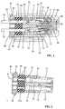
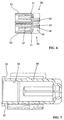
- the connector embodying the present invention shown in Figs. 1 to 10 for electrically connecting a plurality of terminals 20 in a predetermined connection pattern with a bus bar 55 has a housing 10, a plurality of the terminals 20, a sealing member 30, a seal holder 40, two bus bar units 50, and a cap 60.
- the housing 10 is made of a synthetic resinous material.
- the housing 10 has cavities 11 arranged in upper and lower rows and extending through the housing 10 in a front-to-rear direction. In each of the upper and lower rows, the cavities 11 are arranged widthwise at regular intervals. The front half region of the upper-row cavities 11 and the lower-row cavities 11 are open at the upper and lower surfaces of the housing 10, respectively. In each open portion, locking lances (i.e. locking members) 12 project forward in a cantilever manner. Between the upper and lower rows of the cavities 11 there is formed a wide recess 13 for allowing the peripheral walls of the bus bar units 50 to penetrate. An upper surface wall and a lower surface wall of the recess 13 are partly cut away to allow communication with the cavities 11.
- the lance 12 retains and prevents the removal of the terminal 20 inserted into the cavity 11. In cooperation with a cylindrical portion 53 of the bus bar unit 50 it is also used for detecting the degree of insertion of the terminal 20.
- the lance 12 can be outwardly elastically displaced relative to an outer surface 10A of the housing 10. Before the terminal 20 is inserted into the cavity 11 or when the terminal is fully inserted therein, the lance 12 is undeformed, and an outer surface 12A of the lance (the upper surface of the lance in Figs. 8 to 10) is flush with the outer surface 10A of the housing 10. In this state, a removal prevention projection 12B formed at a front end of the lance 12 is engaged in a locking hole 24 of the terminal 20, thus preventing removal of the terminal 20.
- the removal prevention projection 12B interferes with the outer surface of a mating portion 21 of the terminal 20.
- the lance 12 is elastically displaced outward such that the outer surface 12A is located outwardly from the outer surface 10A of the housing 10. Therefore, when the bus bar unit 50 is installed on the housing 10, the cylindrical portion 53 of the bus bar unit 50 collides with the front end of the lance 12. This prevents the completion of the bus bar unit-installing operation.
- an excess-flexure prevention inclined surface 12C for preventing the lance 12 from flexing excessively beyond the limit of its elasticity, when the cylindrical portion 53 collides with the front end of the lance 12.
- a balancing inclined surface 12D inclining in a direction opposite to the direction of inclination of the excess-flexure prevention inclined surface 12C. That is, in a side view the front-end surface of the lance 12 is recessed in the shape of a "V".
- the inward side (i.e. the terminal side) of the front-end surface of the lance 12 is the excess-flexure prevention inclined surface 12C and the outer side of the front-end surface is the balancing inclined surface 12D.
- the cylindrical portion 53 collides with the excess-flexure prevention inclined surface 12C when the bus bar unit 50 is installed on the housing 10.
- the excess-flexure prevention inclined surface 12C is so inclined that the lance 12 is then urged in a direction (downward in Figs. 8 to 10) which reduces the elastic deformation of the lance.
- the cylindrical portion 53 is also capable of colliding with the balancing inclined surface 12D, when the bus bar unit 50 is installed on the housing 10.
- the balancing inclined surface 12D is inclined so that the lance 12 is then urged in a direction in which the elastic displacement of the lance 12 increases (upward in Figs. 8 to 10).
- the cylindrical portion 53 contacts both the excess-flexure prevention inclined surface 12C, and the balancing inclined surface 12D.
- the acute angle ⁇ between the direction of insertion of the cylindrical portion 53 and the excess-flexure prevention inclined surface 12C is smaller than the angle ⁇ between the insertion direction and the balancing inclined surface 12D.
- Each terminal 20 is made of a metal plate material punched into a predetermined configuration.
- the front half part of the terminal 20 is formed as a square pillar-shaped mating portion 21 open forward and rearward.
- the rear half of the terminal 20 is formed as an electric wire connection portion 22 crimped to the core of an electric wire 25.
- a resilient contact piece 23 that contacts a connection piece 57 of the bus bar 55 is formed inside the mating portion 21.
- a locking hole 24 which the locking lance 12 of the housing 10 engages is formed on a peripheral wall of the mating portion 21.
- the terminal 20 is inserted into the cavity 11 of the housing 10 by passing it through the seal member 30 and the seal holder 40 installed on the housing 10 from the rear of the housing 10.
- the lance 12 Immediately before the terminal 20 reaches its fully inserted position, the lance 12 interferes with the peripheral surface of the mating portion 21. Therefore, the lance 12 flexes elastically outward from the housing 10. When the terminal 20 reaches the fully inserted position, the lance 12 is elastically restored to its original state and is engaged in the locking hole 24, thus preventing the terminal 20 from being removed from the cavity 11. The orientation of the terminals in the upper row of cavities 11 is reversed relative to that of the terminals in the lower cavity row.
- the sealing member 30 is made of rubber, oval-shaped, and thick.
- the sealing member 30 is installed on the housing 10 by sandwiching it between the rear end surface of the housing 10 and the front end surface of the seal holder 40.
- a plurality of sealing holes 31 open at the front and rear surfaces of the sealing member 30 is formed coincident with the cavities 11 of the housing 10.
- Each sealing hole 31 is circular.
- a lip portion 31A of corrugated shape having three convexities is circumferentially formed on the inner peripheral surface of each sealing hole 31.
- the inner diameter of the lip portion 31A is smaller than the outer diameter of the coating of the wire 25.
- the peripheral edge of the sealing member 30 is formed as a corrugated sealing edge.
- a lip portion 34 having three convexities approximately semi-circular in section extends circumferentially around the sealing member 30. The lip portion 34 contacts the inner peripheral surface of the cap 60 elastically, thus sealing between the sealing member 30 and the cap 60.
- the seal holder 40 is made of a relatively rigid synthetic resin material. Similarly to the sealing member 30, the seal holder 40 is oval-shaped and thick. The lip portion 34 formed on the periphery of the sealing member 30 is slightly larger than the periphery of the seal holder 40.
- a plurality of terminal insertion openings 41 extend between the front and rear end surfaces of the seal holder 40 in correspondence to the cavities 11 and the sealing holes 31. Each terminal 20 is inserted into the cavity 11 through the terminal insertion opening 41.
- Two locking projections 44 are formed at each of both ends of upper and lower flat peripheral surfaces of the seal holder 40.
- the locking projections 44 engage the cap 60, thus hindering the cap 60 from being easily removed from the housing 10, the sealing member 30, and the seal holder 40.
- An index projection 45 is formed in each circular arc-shaped region located at right and left ends of the peripheral surface of the seal holder 40.
- each of a pair of the index projections 45 is formed such that the inward side thereof is on a level higher than that of the outward side thereof.
- the index projection 45 serves as an index for checking the upper and lower sides of the housing 10 when the terminal fixture 20 is inserted into the cavity 11.
- the bus bar unit 50 is composed of a holding member 51 made of a relatively rigid synthetic resin material and a metal bus bar 55 integrated with the holding member 51 by insert molding.
- the holding member 51 has a wide sheet-shaped holding portion 52 and a flat cylindrical portion 53 projecting rearward (direction toward the housing 10) from the sheet-shaped holding portion 52.
- the bus bar 55 consists of a plurality of connection pieces 57 projecting in parallel with each other in the shape of a cantilever from an edge of a belt-shaped carrier 56.
- the bus bar 55 is held, with the carrier 56 disposed along the sheet-shaped holding portion 52 and with connection pieces 57 facing the cylindrical portion 53.
- a punched hole 54 is formed on the sheet-shaped holding portion 52 in correspondence to the gap between adjacent connection pieces 57 projecting from the carrier 56.
- the carrier 56 In the process of producing the bus bar unit 50, a portion of the carrier 56 facing each punched hole 54 is punched with a punch and die in correspondence to a predetermined connection pattern. As a result, the carrier 56 is divided (not shown) into a plurality of bus bars 55.
- One bus bar 55 has at least three connection pieces 57.
- a plurality of terminals 20 are connected by each bus bar 55 through the connection pieces 57.
- Each bus bar unit 50 is installed on the housing 10 in a direction forward therefrom such that the cylindrical portion 53 covers the upper-row cavities 11 or the lower-row cavities 11.
- the connection pieces 57 are connected with the terminals 20.
- Connection patterns can be discriminated from each other by changing the color of the holding member 51 of the bus bar unit 50.
- the upper part of the holding member 51 and the lower part thereof are not symmetrical with each other.
- the required bus bar unit 50 can be installed on the housing 10 in a correct direction, and a group of the terminal fixtures 20 can be connected in a correct pattern by checking colors and directions of the holding members 51.
- a guide groove 58 extending longitudinally is formed at each of right and left widthwise edges of the cylindrical portion 53.
- Front and rear locking projections 17 and 18 corresponding to the guide groove 58 are formed on the housing 10.
- the bus bar unit 50 is brought to a temporary locking position by locking the rear end of the cylindrical portion 53 and that of the guide groove 58 by the locking projections 17 and 18, with the cylindrical portion 53 and the guide groove 58 sandwiched between the locking projections 17 and 18.
- the bus bar unit 50 is held at a temporary locking position.
- the connection piece 57 is placed at a retracted position at which it does not contact the terminal 20, thus preventing generation of resistance at the time of the insertion of the terminal 20.
- the bus bar unit 50 is then brought to a normal or final installation position by locking the front end of the guide groove 58 and the rear end thereof to the locking projections 17 and 18 respectively, with the front and rear ends of the guide groove 58 sandwiching the locking projection 17 and the locking projection 18.
- the bus bar unit 50 connects the terminals 20 one to another and can be used to detect the inserted state of the terminals 20.
- the cylindrical portion 53 is installed on the housing 10 by sliding it along the outer surface 10A of the housing 10.
- An inclined surface 53A is formed on the front-end surface of the cylindrical portion 53 such that the outer side thereof extends further than the inner side (housing side) thereof.
- the inner-side edge of the collision inclined surface 53A is a prevention edge 53B capable of contacting the excess-flexure prevention inclined surface 12C of the lance 12.
- the outer-side edge of the collision inclined surface 53A is a balancing edge 53C which contacts the balancing inclined surface 12D of the lance 12.
- the cap 60 is made of a relatively rigid synthetic resin material.
- the cap 60 is oval-shaped in a front view and has a closed bottom.
- Locking holes 61 to which the locking projections 44 of the seal holder 40 lock are formed at the edge of the open mouth of the cap 60.
- the cap 60 is locked in the installed state by the engagement between the locking projections 44 and the locking holes 61.
- Relief portions 62 projecting outwardly are formed on the edge of the open mouth of the cap 60 to prevent the cap 60 from interfering with the index projections 45 of the seal holder 40.
- the region of the inner peripheral surface of the cap 60 near the edge of its open mouth is formed as a sealing surface 63 with which the lip portion 34 formed on the peripheral edge of the sealing member 30 contacts elastically.
- the assembly procedure is as follows:
- the sealing member 30 is sandwiched between the seal holder 40 and the housing 10. Then, a projection (not shown) formed on the housing 10 is passed through the sealing member 30 and the tip of the projection is locked to the seal holder 40. This locks the seal member 30 to the housing 10, and the removal of the seal holder 40 is prevented. Then, the terminals 20 are inserted through the opening 41 and the holes 31 into the cavity 11. Thereafter, the bus bar unit 50 is installed at a temporary locking position on the housing 10, and the bus bar unit 50 is placed on an assembling apparatus not shown. Thereafter, the bus bar unit 50 is pressed to a normal installation portion from the temporary locking position. As a result, the terminal 20 are connected in a predetermined pattern. When the bus bar unit or units 50 are in the normal installing position, finally, the cap 60 is installed on the housing 10 in such a manner that the cap 60 covers the housing 10 and the bus bar unit 50.
- the lip portion 34 formed on the periphery of the sealing member 30 prevents water from penetrating into the cap 60 between the inner periphery of the cap 60 and the periphery of the sealing member 30. Further, the lip portion 31A of the sealing hole 31 contacts the periphery of the wire 25 closely, the inner periphery of the fit-in hole 32 contacts the periphery of the holding projection 14, and the inner periphery of the fit-in hole 33 contacts the periphery of the deformation prevention projection 15. Therefore, water can be prevented from penetrating into the sealing member 30 from outside.
- each lance 12 is undeformed so that its outer surface 12A is flush with the outer surface 10A of the housing 10. Accordingly, when the cylindrical portion 53 slides over the outer surface 10A of the housing 10 during bus bar unit-installation, the cylindrical portion 53 does not interfere with the lances 12. Thus, the bus bar unit 50 can be installed on the housing securely.
- the cylindrical portion 53 faces the lances 12 in such a manner that the inner surface of the cylindrical portion 53 presses downward on the outer surfaces 12A of the lances 12.
- the lances 12 are prevented from being elastically displaced in a direction which would move them away from the terminals 20 (see Fig. 8).
- the removal prevention projection 12B interferes with the outer surface of the mating portion 21 of the terminal 20.
- the lance 12 is elastically displaced outward, and projects outward from the outer surface 10A of the housing 10.
- the inclined surface 53A formed at the front end of the cylindrical portion 53 then contacts the outer-side edge of the lance 12. As a result, the installation operator notices that the installation resistance is suddenly increased. In this manner, the operator can detect that a terminal is in the incomplete inserted state (see Fig. 9).
- the operator suspends the installation operation with the connector in the state shown in Fig. 9 and resumes the installation operation after inserting the terminal fitting 20 into the normal position of the cavity 11. However, it may happen that the operator continues to perform the installing operation without noticing a sudden increase in installation resistance.
- the lance 12 is then displaced upward in Fig. 9 by a force acting in the bus bar unit-installation direction, the balancing edge 53C of the cylindrical portion 53 contacting and transmitting the force to the balancing inclined surface 12D. If the lance 12 were to flex upward further and exceed the limit of its elasticity, it would not be restorable to the undeformed state shown in Fig. 8.
- the lance 12 flexes further, to a position still within its elastic limit, the prevention edge 53B of the cylindrical portion 53 contacts the excess-flexure prevention inclined surface 12C (see Fig. 10).
- the excess-flexure prevention inclined surface 12C has an inclination so that the lance 12 is urged in the opposite (elasticity-restoring) direction by the collision force of the cylindrical portion 53 applied to the excess-flexure prevention inclined surface 12C.
- the lance 12 is prevented from being elastically displaced further.
- the cylindrical portion 53 is pressed against the excess-flexure prevention inclined surface 12C.
- the housing 10 it is also unnecessary to provide the housing 10 with a wall for preventing excess deformation of the lance 12, which makes it possible to reduce the width of the housing 10.
- the lance 12 is prevented from being displaced in either direction.
- installation of the bus bar unit 50 on the housing 10 is prevented. That is, even if the bus bar unit 50 is pressed strongly against the lance 12, the lance 12 is prevented from being forcibly displaced in the elasticity-restoring direction.
- the lance 12 is spaced from the terminal fitting 20. Therefore, even though the lance 12 may be displaced slightly in the elasticity-restoring direction, there is no possibility that the lance 12 is urged excessively against the terminal 20.
- the acute angle ⁇ formed between the insertion direction of the cylindrical portion 53 and the excess-flexure prevention inclined surface 12C is smaller than the angle ⁇ which formed between the insertion direction and the balancing inclined surface 12D.
- the collision inclined surface 53A of the cylindrical portion 53 inclines with respect to the bus bar unit-installation direction. Therefore, even if the lances 12 may be slightly proud of the outer surface 10A of the housing 10 when the terminals 20 are fully inserted, the lances 12 are not snagged by the inner-side edge (prevention edge 53B) of the cylindrical portion 53 during installation of the bus bar unit 50 on the housing 10.
- the present invention is not limited to the embodiment described, but may be varied for example as described below.
Landscapes
- Connector Housings Or Holding Contact Members (AREA)
Applications Claiming Priority (6)
| Application Number | Priority Date | Filing Date | Title |
|---|---|---|---|
| JP10592099 | 1999-04-13 | ||
| JP10591999 | 1999-04-13 | ||
| JP10592099A JP3362698B2 (ja) | 1999-04-13 | 1999-04-13 | 防水ジョイントコネクタ |
| JP11105919A JP2000299156A (ja) | 1999-04-13 | 1999-04-13 | ジョイントコネクタ |
| JP11847999A JP3367463B2 (ja) | 1999-04-26 | 1999-04-26 | ジョイントコネクタ |
| JP11847999 | 1999-04-26 |
Publications (3)
| Publication Number | Publication Date |
|---|---|
| EP1045482A2 true EP1045482A2 (fr) | 2000-10-18 |
| EP1045482A3 EP1045482A3 (fr) | 2002-06-12 |
| EP1045482B1 EP1045482B1 (fr) | 2006-03-01 |
Family
ID=27310609
Family Applications (1)
| Application Number | Title | Priority Date | Filing Date |
|---|---|---|---|
| EP00303000A Expired - Lifetime EP1045482B1 (fr) | 1999-04-13 | 2000-04-10 | Connecteur |
Country Status (3)
| Country | Link |
|---|---|
| US (1) | US6290521B1 (fr) |
| EP (1) | EP1045482B1 (fr) |
| DE (1) | DE60026234T2 (fr) |
Cited By (4)
| Publication number | Priority date | Publication date | Assignee | Title |
|---|---|---|---|---|
| EP1484821A1 (fr) * | 2003-06-06 | 2004-12-08 | Tyco Electronics Corporation | Connecteur électrique étanche |
| EP2144335A1 (fr) * | 2008-07-08 | 2010-01-13 | Sumitomo Wiring Systems, Ltd. | Connecteur, faisceau de câbles ayant un tel connecteur et procédé de connexion |
| WO2011040649A1 (fr) * | 2009-10-01 | 2011-04-07 | Yazaki Corporation | Connecteur |
| EP2437357A1 (fr) * | 2010-10-01 | 2012-04-04 | Sumitomo Wiring Systems, Ltd. | Connecteur |
Families Citing this family (11)
| Publication number | Priority date | Publication date | Assignee | Title |
|---|---|---|---|---|
| JP3691300B2 (ja) * | 1999-08-26 | 2005-09-07 | 矢崎総業株式会社 | 防水コネクタ |
| JP2002100433A (ja) * | 2000-07-17 | 2002-04-05 | Yazaki Corp | リテーナ付きコネクタ |
| JP2002260766A (ja) * | 2001-02-27 | 2002-09-13 | Yazaki Corp | コネクタ |
| US6935893B1 (en) * | 2004-02-11 | 2005-08-30 | Molex Incorporated | Electrical connector with terminal position assurance device |
| JP4259453B2 (ja) * | 2004-10-29 | 2009-04-30 | 住友電装株式会社 | 防水コネクタ |
| JP2006253017A (ja) * | 2005-03-11 | 2006-09-21 | Sumitomo Wiring Syst Ltd | ジョイントコネクタ |
| EP2279539A1 (fr) | 2008-05-15 | 2011-02-02 | Johnson Controls Saft Advanced Power Solutions LLC | Système de batterie |
| JP5542238B2 (ja) * | 2010-03-25 | 2014-07-09 | 矢崎総業株式会社 | ジョイントコネクタ及びジョイントコネクタにおけるバスバーパターン識別方法 |
| JP5644563B2 (ja) | 2011-02-07 | 2014-12-24 | 住友電装株式会社 | コネクタ |
| US11283211B2 (en) | 2018-05-18 | 2022-03-22 | Yazaki North America, Inc. | Electrical connector assembly with plug and cavity assembly and method of ultrasonically welding |
| JP7281089B2 (ja) * | 2019-11-29 | 2023-05-25 | 住友電装株式会社 | コネクタ |
Family Cites Families (14)
| Publication number | Priority date | Publication date | Assignee | Title |
|---|---|---|---|---|
| JPH0261082U (fr) | 1988-10-28 | 1990-05-07 | ||
| FR2650707B1 (fr) * | 1989-08-07 | 1991-10-11 | Labinal | Dispositif de shuntage pour faisceaux de conducteurs electriques |
| JPH0715188Y2 (ja) | 1990-04-20 | 1995-04-10 | 富士通株式会社 | 密着ケースの開放構造 |
| US5201667A (en) * | 1990-06-27 | 1993-04-13 | Yazaki Corporation | Branch circuit structure |
| JP2570363Y2 (ja) * | 1992-09-07 | 1998-05-06 | 矢崎総業株式会社 | コネクタの解除感知機構 |
| FR2706687B1 (fr) * | 1993-06-15 | 1995-08-11 | Cinch Connecteurs Sa | Elément de boîtier de connecteur électrique. |
| JP2567958Y2 (ja) * | 1993-12-07 | 1998-04-08 | 住友電装株式会社 | コネクタ |
| JP2982107B2 (ja) * | 1994-10-19 | 1999-11-22 | 矢崎総業株式会社 | コネクタの半嵌合検知構造 |
| JPH08250176A (ja) * | 1995-03-13 | 1996-09-27 | Sumitomo Wiring Syst Ltd | コネクタ |
| JP3463832B2 (ja) * | 1995-05-02 | 2003-11-05 | 矢崎総業株式会社 | 端子係止具を備えたコネクタ |
| US5769650A (en) * | 1995-06-19 | 1998-06-23 | Sumitomo Wiring Systems, Ltd. | Connector and cover therefor |
| JP3239330B2 (ja) * | 1996-01-31 | 2001-12-17 | 矢崎総業株式会社 | ジョイントコネクタの製造方法 |
| JP3230996B2 (ja) * | 1996-09-12 | 2001-11-19 | 矢崎総業株式会社 | コネクタ |
| JPH11238542A (ja) * | 1998-02-20 | 1999-08-31 | Yazaki Corp | コネクタ |
-
2000
- 2000-04-10 DE DE60026234T patent/DE60026234T2/de not_active Expired - Lifetime
- 2000-04-10 EP EP00303000A patent/EP1045482B1/fr not_active Expired - Lifetime
- 2000-04-10 US US09/545,829 patent/US6290521B1/en not_active Expired - Lifetime
Cited By (8)
| Publication number | Priority date | Publication date | Assignee | Title |
|---|---|---|---|---|
| EP1484821A1 (fr) * | 2003-06-06 | 2004-12-08 | Tyco Electronics Corporation | Connecteur électrique étanche |
| US7077701B2 (en) | 2003-06-06 | 2006-07-18 | Tyco Electronics Corporation | Sealed electrical connector |
| EP2144335A1 (fr) * | 2008-07-08 | 2010-01-13 | Sumitomo Wiring Systems, Ltd. | Connecteur, faisceau de câbles ayant un tel connecteur et procédé de connexion |
| WO2011040649A1 (fr) * | 2009-10-01 | 2011-04-07 | Yazaki Corporation | Connecteur |
| CN102549849A (zh) * | 2009-10-01 | 2012-07-04 | 矢崎总业株式会社 | 连接器 |
| US8641458B2 (en) | 2009-10-01 | 2014-02-04 | Yazaki Corporation | Connector having locking lance with lance beak part and locking projection |
| CN102549849B (zh) * | 2009-10-01 | 2015-08-12 | 矢崎总业株式会社 | 连接器 |
| EP2437357A1 (fr) * | 2010-10-01 | 2012-04-04 | Sumitomo Wiring Systems, Ltd. | Connecteur |
Also Published As
| Publication number | Publication date |
|---|---|
| US6290521B1 (en) | 2001-09-18 |
| EP1045482A3 (fr) | 2002-06-12 |
| DE60026234T2 (de) | 2006-12-14 |
| EP1045482B1 (fr) | 2006-03-01 |
| DE60026234D1 (de) | 2006-04-27 |
Similar Documents
| Publication | Publication Date | Title |
|---|---|---|
| EP1045482B1 (fr) | Connecteur | |
| US6193549B1 (en) | Waterproof connector for electrical terminals | |
| EP1045483B1 (fr) | Combinaison d'un connecteur et dispositif d'assemblage | |
| EP0895312B1 (fr) | Connecteur électrique avec dispositif è assurer la position dest terminaux | |
| US4959023A (en) | Electrical connector | |
| CA1286379C (fr) | Connecteur | |
| EP1160929B1 (fr) | Connecteur étanche à l'eau, boítier pour connecteur et élément d'étanchéité correspondant | |
| EP0818855B1 (fr) | Connecteur | |
| EP0551128B1 (fr) | Assemblage de connecteurs enfichable | |
| EP0727844B1 (fr) | Connecteur électrique | |
| EP0822620B1 (fr) | Contact pour shunt et connecteur électrique correspondant | |
| US5839915A (en) | Lock detecting structure of connector | |
| US5823807A (en) | Connector assembly with mechanism for confirmation of fitting of connector housing and method of attaching connector housing | |
| EP1889332B1 (fr) | Ensemble connecteur comprenant un dispositif de maintien de position des bornes | |
| EP1091451B1 (fr) | Connecteur | |
| EP0883213A2 (fr) | Connecteur | |
| EP0978905B1 (fr) | Connecteur | |
| EP1033788B1 (fr) | Connecteur à verrouillage secondaire | |
| KR19990062930A (ko) | 단자 보유 시스템을 갖는 전기 커넥터 조립체 | |
| EP0963008B1 (fr) | Un connecteur et un couvercle associé | |
| EP0427415B1 (fr) | Connecteur de traversée étanche pour véhicules | |
| KR19990062929A (ko) | 단자 위치 보장 장치를 갖는 전기 커넥터 | |
| US6422894B1 (en) | Connector fitting detection construction | |
| JP3367463B2 (ja) | ジョイントコネクタ | |
| US20060116017A1 (en) | Electrical connector housing, electrical connector, and connector assembly |
Legal Events
| Date | Code | Title | Description |
|---|---|---|---|
| PUAI | Public reference made under article 153(3) epc to a published international application that has entered the european phase |
Free format text: ORIGINAL CODE: 0009012 |
|
| 17P | Request for examination filed |
Effective date: 20000502 |
|
| AK | Designated contracting states |
Kind code of ref document: A2 Designated state(s): AT BE CH CY DE DK ES FI FR GB GR IE IT LI LU MC NL PT SE |
|
| AX | Request for extension of the european patent |
Free format text: AL;LT;LV;MK;RO;SI |
|
| PUAL | Search report despatched |
Free format text: ORIGINAL CODE: 0009013 |
|
| AK | Designated contracting states |
Kind code of ref document: A3 Designated state(s): AT BE CH CY DE DK ES FI FR GB GR IE IT LI LU MC NL PT SE |
|
| AX | Request for extension of the european patent |
Free format text: AL;LT;LV;MK;RO;SI |
|
| AKX | Designation fees paid |
Designated state(s): DE GB |
|
| 17Q | First examination report despatched |
Effective date: 20050503 |
|
| GRAP | Despatch of communication of intention to grant a patent |
Free format text: ORIGINAL CODE: EPIDOSNIGR1 |
|
| GRAS | Grant fee paid |
Free format text: ORIGINAL CODE: EPIDOSNIGR3 |
|
| GRAA | (expected) grant |
Free format text: ORIGINAL CODE: 0009210 |
|
| AK | Designated contracting states |
Kind code of ref document: B1 Designated state(s): DE GB |
|
| REG | Reference to a national code |
Ref country code: GB Ref legal event code: FG4D |
|
| REF | Corresponds to: |
Ref document number: 60026234 Country of ref document: DE Date of ref document: 20060427 Kind code of ref document: P |
|
| PG25 | Lapsed in a contracting state [announced via postgrant information from national office to epo] |
Ref country code: GB Free format text: LAPSE BECAUSE OF NON-PAYMENT OF DUE FEES Effective date: 20060601 |
|
| PLBE | No opposition filed within time limit |
Free format text: ORIGINAL CODE: 0009261 |
|
| STAA | Information on the status of an ep patent application or granted ep patent |
Free format text: STATUS: NO OPPOSITION FILED WITHIN TIME LIMIT |
|
| 26N | No opposition filed |
Effective date: 20061204 |
|
| GBPC | Gb: european patent ceased through non-payment of renewal fee |
Effective date: 20060601 |
|
| REG | Reference to a national code |
Ref country code: DE Ref legal event code: R084 Ref document number: 60026234 Country of ref document: DE |
|
| PGFP | Annual fee paid to national office [announced via postgrant information from national office to epo] |
Ref country code: DE Payment date: 20190326 Year of fee payment: 20 |
|
| REG | Reference to a national code |
Ref country code: DE Ref legal event code: R071 Ref document number: 60026234 Country of ref document: DE |