EP1045593A1 - Bilddekoder und -koder - Google Patents
Bilddekoder und -koder Download PDFInfo
- Publication number
- EP1045593A1 EP1045593A1 EP99929878A EP99929878A EP1045593A1 EP 1045593 A1 EP1045593 A1 EP 1045593A1 EP 99929878 A EP99929878 A EP 99929878A EP 99929878 A EP99929878 A EP 99929878A EP 1045593 A1 EP1045593 A1 EP 1045593A1
- Authority
- EP
- European Patent Office
- Prior art keywords
- error
- section
- block
- value
- image
- Prior art date
- Legal status (The legal status is an assumption and is not a legal conclusion. Google has not performed a legal analysis and makes no representation as to the accuracy of the status listed.)
- Withdrawn
Links
Images



























Classifications
-
- H—ELECTRICITY
- H04—ELECTRIC COMMUNICATION TECHNIQUE
- H04N—PICTORIAL COMMUNICATION, e.g. TELEVISION
- H04N21/00—Selective content distribution, e.g. interactive television or video on demand [VOD]
- H04N21/60—Network structure or processes for video distribution between server and client or between remote clients; Control signalling between clients, server and network components; Transmission of management data between server and client, e.g. sending from server to client commands for recording incoming content stream; Communication details between server and client
- H04N21/65—Transmission of management data between client and server
- H04N21/654—Transmission by server directed to the client
-
- H—ELECTRICITY
- H04—ELECTRIC COMMUNICATION TECHNIQUE
- H04N—PICTORIAL COMMUNICATION, e.g. TELEVISION
- H04N19/00—Methods or arrangements for coding, decoding, compressing or decompressing digital video signals
- H04N19/10—Methods or arrangements for coding, decoding, compressing or decompressing digital video signals using adaptive coding
- H04N19/134—Methods or arrangements for coding, decoding, compressing or decompressing digital video signals using adaptive coding characterised by the element, parameter or criterion affecting or controlling the adaptive coding
- H04N19/164—Feedback from the receiver or from the transmission channel
-
- H—ELECTRICITY
- H04—ELECTRIC COMMUNICATION TECHNIQUE
- H04N—PICTORIAL COMMUNICATION, e.g. TELEVISION
- H04N19/00—Methods or arrangements for coding, decoding, compressing or decompressing digital video signals
- H04N19/60—Methods or arrangements for coding, decoding, compressing or decompressing digital video signals using transform coding
-
- H—ELECTRICITY
- H04—ELECTRIC COMMUNICATION TECHNIQUE
- H04N—PICTORIAL COMMUNICATION, e.g. TELEVISION
- H04N19/00—Methods or arrangements for coding, decoding, compressing or decompressing digital video signals
- H04N19/65—Methods or arrangements for coding, decoding, compressing or decompressing digital video signals using error resilience
-
- H—ELECTRICITY
- H04—ELECTRIC COMMUNICATION TECHNIQUE
- H04N—PICTORIAL COMMUNICATION, e.g. TELEVISION
- H04N19/00—Methods or arrangements for coding, decoding, compressing or decompressing digital video signals
- H04N19/85—Methods or arrangements for coding, decoding, compressing or decompressing digital video signals using pre-processing or post-processing specially adapted for video compression
- H04N19/89—Methods or arrangements for coding, decoding, compressing or decompressing digital video signals using pre-processing or post-processing specially adapted for video compression involving methods or arrangements for detection of transmission errors at the decoder
-
- H—ELECTRICITY
- H04—ELECTRIC COMMUNICATION TECHNIQUE
- H04N—PICTORIAL COMMUNICATION, e.g. TELEVISION
- H04N21/00—Selective content distribution, e.g. interactive television or video on demand [VOD]
- H04N21/60—Network structure or processes for video distribution between server and client or between remote clients; Control signalling between clients, server and network components; Transmission of management data between server and client, e.g. sending from server to client commands for recording incoming content stream; Communication details between server and client
- H04N21/63—Control signaling related to video distribution between client, server and network components; Network processes for video distribution between server and clients or between remote clients, e.g. transmitting basic layer and enhancement layers over different transmission paths, setting up a peer-to-peer communication via Internet between remote STB's; Communication protocols; Addressing
- H04N21/633—Control signals issued by server directed to the network components or client
- H04N21/6332—Control signals issued by server directed to the network components or client directed to client
Definitions
- the present invention relates to a mounting technique for an image decoding device and image encoding device complying to various international standards for moving image compression and expansion.
- the present invention relates to an image decoding device and image encoding device which increases resistance to bit error generated in encoded bit streams.
- the ITU-T (International Telecommunication Union-Telecommunication Sector) Recommendation H.263 is known as a means of encoding and decoding image signals.
- H. 263 divides the encoding and decoding of moving image data into a plurality of hierarchies.
- Fig. 1 shows the structure of video data hierarchies in H.263.
- the layer in an uppermost position is called a picture layer.
- the picture layer is comprised from a plurality of GOB (Group of Blocks) layers.
- GOB Group of Blocks
- a macroblock layer exists in a lower layer of the GOB layers and a block layer exists in a lower layer of the macroblock layer.
- Fig. 2 shows the structure of a macroblock.
- One macroblock is comprised of six blocks (8 pixels x 8 lines) with block numbers 1 ⁇ 6 as shown in Fig. 2.
- Block numbers 1 ⁇ 4 are blocks for luminance components.
- Block numbers 5, 6 are color difference component blocks.
- Fig. 3 shows an example of a conventional encoded bit stream.
- Binary digit strings which are respectively called picture start codes (PSC), and GOB start codes (GBSC) are added to the header of picture layer information and GOB layer information.
- PSC picture start codes
- GBSC GOB start codes
- SC start codes
- a GOB number or the like which is a number of the relevant GOB is contained in the GOB layer information.
- Layer information such as quantization step size, encoded mode which shows intra-encoded or inter-encoded is contained in the macro block (MB) layer information. Thereafter the block data information is stored.
- MB macro block
- Intra-encoded is an encoded mode which encodes only picture data itself of encoded images without using other pictures.
- Inter-encoded is an encoded mode which encodes picture information of encoded images using information of other pictures with a time frame.
- Fig. 4 is a block diagram showing the structure of a conventional image decoding device using H. 263.
- An encoded bit stream which is encoded is input into a syntax analysis section 1.
- Each layer of information of picture layer, GOB layer and macroblock layer is analyzed and decoded on the basis of the H. 263 syntax. Thus block data information is analyzed.
- an error syntax detection signal 1e to that effect is output to the error processor 7.
- the obtained quantization step size 1d is output to a reverse quantization processor 5 and the encoded mode 1b is output to a reverse DCT/decoding image generator 6.
- analyzed block data information is information determined by the H. 263 decoding method
- the syntax analysis section 1 determines that errors are not contained in the input encoded bit stream due to the influence of errors contained in an encoded bit stream even if the block data information to be analyzed is different block data information.
- a quantization index column 1a for a decoded block unit is output to the reverse quantization processor 5.
- the quantization index column 1a is comprised of columns of quantization indexes.
- a quantization index is a quantization DCT coefficient.
- a reverse quantization process applied to the quantization index column 1a of the block unit is provided in the reverse quantization processor 5 using a quantization step size 1d input from the syntax analysis section 1.
- a DCT coefficient column 1f of a block unit is output to the reverse DCT/decoding image generator 6.
- a reverse DCT process is provided with respect to the DCT coefficient column if of the block unit in the reverse DCT/decoding generator 6, a decoded image is generated based on the input encoded mode 1b and the generated decoded image is output.
- the error processor 7 generates and outputs a decoded image by error suppression based on a fixed method on receipt of an error syntax detection signal 1e which shows layer information or block data information from the syntax analysis section 1 which does not match a fixed syntax.
- the problem has arisen that error detection can not be performed since the image decoding device analyzes and performs decoding without recognizing the generation of errors in the encoded bit stream.
- the block data information being block data information which is adapted to a fixed syntax which is predetermined on the encoded and decoded sides such as in the case of an H. 263 video method or the like. This is the case even if the block data information which is different from the block data information which is to be analyzed is analyzed by an encoded bit stream due to the influence of errors contained in the encoded bit stream.
- the present invention is proposed to solve the above problems and has the object of providing an image decoding device which can perform error detection even when block data information is adapted to a fixed syntax and such block data information, which differs from the block data information which should be analyzed, is analyzed by encoded bit stream.
- the invention has a further object of obtaining an image encoding device generating an encoded bit stream which can effectively detect errors contained in an encoded bit stream in the image decoding device.
- the error block detection means controls the sensitivity of error detection based on a control signal output from the monitoring means.
- An image decoding device which performs image expansion processing and reverse orthogonal conversion on fixed block units with respect to image compression data.
- the image decoding device comprises an error block detection means which receives a threshold value and image signal in a frequency band, determines whether or not a block data error is contained therein based on the threshold value and the image signal in a frequency band and outputs an error detection state in block data.
- An image encoding device divides image data into block units, performs orthogonal conversion and performs compression coding on each block unit.
- the image encoding device comprises an encoded data value limiting means which receives a threshold value and an image signal in a frequency band and which outputs an image signal with an added limit in a frequency band based on a predetermined threshold value and an image signal in a frequency band.
- An image decoding device comprises the invention as claimed in Claim 1 or Claim 2 and is characterized in that the error block detection means receives a threshold value defining a range of values of an image signal value in a frequency band and an image signal in a frequency band.
- the error block detection means performs error detection on block data based on whether an image signal value in a frequency band is contained in the range of values or not and outputs an error detection state.
- An image decoding device comprises the invention as claimed in Claim 1 or Claim 2 and is characterized in that the error block detection means receives a threshold value variably defining a range of values of an image signal value in a frequency band, which performs error detection on block data based on whether an image signal value in a frequency band is contained in the range of variable values and which outputs an error detection state.
- An image encoding device comprises the invention as claimed in Claim 3 and is characterized in that the encoded data value limiting means receives a threshold value defining a range of values of image signal values in a frequency band and an image signal in a frequency band.
- the encoded data value limiting means replaces an image signal value in the converted frequency band with a value contained in the range of values based on whether an image signal value in the converted frequency band is contained in the range of values and outputs encoded data.
- An image encoding device comprises the invention as claimed in Claim 3 and is characterized in that the encoded data value limiting means receives a threshold value variably defining a range of values of an image signal value in a frequency band and an image signal in a frequency band.
- the encoded data value limiting means replaces an image signal value in the converted frequency band to a value contained in the range of values based on whether an image signal value in the converted frequency band is contained in the range of values and outputs encoded data.
- An image decoding device comprises the invention as claimed in Claim 1 or Claim 2 and is characterized in that the error block detection means receives a threshold value defining a range of frequencies of an image signal list in a frequency band and an image signal in a frequency band, and performs error detection in block data and outputs an error detection state based on whether or not a non-zero coefficient which corresponds to the highest frequency component of the coefficients contained in the image signal list in the frequency bands is contained in the frequency range given by the threshold value.
- An image decoding device comprises the invention as claimed in Claim 1 or Claim 2 and is characterized in that the error block detection means receives a threshold value variably defining a range of frequencies of an image signal list in a frequency band, and performs error detection in block data and outputs an error detection state based on whether or not a non-zero coefficient which corresponds to the highest frequency component of the coefficients contained in the image signal list in the frequency bands is contained in the variable frequency range given by the threshold value.
- An image encoding device comprises the invention as claimed in Claim 3 and is characterized in that the encoded data value limiting means receives a threshold value defining a range of frequencies of an image signal list in a frequency band and an image signal in a frequency band, and outputs encoded data which makes coefficient values, which correspond to frequencies above the threshold value, take a value of zero based on whether or not a non-zero coefficient which corresponds to the highest frequency component of the coefficients contained in the image signal list in the frequency bands is contained in the frequency range given by the threshold value.
- An image encoding device comprises the invention as claimed in Claim 3 and is characterized in that the encoded data value limiting means receives a threshold value variably defining a range of frequencies of an image signal list in a frequency band and an image signal in a frequency band, and outputs encoded data which makes coefficient values, which correspond to frequencies above the threshold value, take a value of zero based on whether or not a non-zero coefficient which corresponds to the highest frequency component of the coefficients contained in the image signal list in the frequency bands is contained in the frequency range variably given by the threshold value.
- An image decoding device comprises the invention as claimed in any one of Claim 1, Claim 2, Claim 4, Claim 5, Claim 8, or Claim 9 and is characterized in that a block column detection means is provided which is given an error detection state output by the error block detection means, which counts the number of blocks determined to contain errors in the block data of the error detection states by a block column unit which is comprised by a plurality of blocks, which performs error detection of data in block columns based on that count number and a preset threshold value and which outputs an error detection state of data in block columns.
- An image encoding device comprises the invention as claimed in Claim 7 or Claim 11, and is provided with a multiplexing means which receives threshold value control information which updates the threshold value and which multiplexes and outputs such threshold value control information to the encoded bit stream.
- An image decoding device comprises the invention as claimed in Claim 5 or Claim 9, and is provided with an analyzing means which decodes and analyzes threshold value control information with an input encoded bit stream.
- An error block detection means inputs threshold value control information decoded and analyzed in the analyzing means, updates the threshold value based on the threshold value control information and performs error detection in the block data and outputs an error detection state based on the updated threshold value and the image signal in the frequency band.
- An image encoding device comprises the invention as claimed in any one of Claim 3, Claim 6, Claim 7, Claim 10, Claim 11 or Claim 13 and is characterized in that a multiplexing means is provided which receives threshold value information used when the encoded data value limiting means limits the image signal distribution in the frequency band and which multiplexes and outputs such threshold value information to the encoded bit stream.
- the encoded data value control means outputs encoded data in which the image signal distribution in the frequency band is limited based on the threshold value information.
- An image decoding device comprises the invention as claimed in any one of Claim 1, Claim 2, Claim 4, Claim 5, Claim 8, Claim 9, Claim 12 or Claim 11 and is characterized in that an analyzing means which decodes and analyzes threshold value information used when limiting the image signal distribution in the frequency band by the encoded bit stream.
- the error block detection means performs error detection in the block data and outputs an error detection state based on the threshold value information decoded and analyzed by the analyzing means.
- An image encoding device comprises the invention as claimed in any one of Claim 3, Claim 6, Claim 7, Claim 10, Claim 11, or Claim 13 and is characterized in that a multiplexing means is provided which multiplexes and outputs limiting operation control information showing whether or not the encoded data value limiting means will perform a limiting operation.
- the encoded data value control means performs a limiting operation based on the limiting operation control information.
- An image decoding device comprises the invention as claimed in any one of Claim 1, Claim 2, Claim 4, Claim 5, Claim 8, Claim 9, Claim 12 or Claim 14 and Claim 16 is characterized in that an analyzing means is provided which analyzes limiting operation control information by the encoded bit stream.
- the error block detection means performs error detection on the block data and outputs an error detection state based on the limiting operation control information analyzed by the analyzing means.
- An image decoding device comprises the invention as claimed in Claim 1, and is provided with a monitoring means which monitors the strength of a received signal of encoded data as a transmission state and outputs a threshold value control signal for controlling a threshold value when the error block detection means performs error detection in block data based on a monitoring result.
- the error block detection means controls a threshold value when performing error block detection based on the threshold value control signal from the monitoring means.
- An image decoding device comprises the invention as claimed in Claim 1 and is characterized in that the monitoring means monitors the generation of bit errors when receiving an encoded signal as a transmission state and outputs an activation control signal which activates or does not activate the error block detection means based on a bit error generation state.
- the error block detection means performs detection operations of error blocks based on the activation control signal from the monitoring means.
- An image decoding device comprises the invention as claimed in Claim 1 and is provided with a monitoring means which inputs a media packet column detects bit errors in the packet based on error detection encoding added to the packet unit, counts the number of bit errors in a media packet unit, and outputs an activation control signal to activate or not activate the error block detection means or not based on a shift in the count value.
- the error block detection means performs an error block detection operation based on the activation control signal from the monitoring means.
- the error block detection section detects an error generated by an encoded bit stream generated by H. 263 video compression encoding in a block unit on the basis of whether a value of an image signal converted to a frequency band is contained in a range set by a maximum value and a minimum value which are preset threshold values.
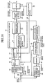
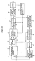
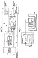
- Fig. 5 is a block diagram of an image decoding device according to a first embodiment of the present invention.
- reference numeral 1 is a syntax analysis section
- 1a is a quantization index column
- 1b is an encoded mode
- 1c is a block number
- 1d is a quantization step size
- 1e is an error syntax detection signal
- 1f is a DCT coefficient column
- 2 is a maximum value/minimum value table storage section
- 3 is a maximum value/minimum value comparison section
- 4a is an error block detection signal.
- 4 is an error block detection section comprised by a maximum value/minimum value table storage section 2 and a maximum value/minimum value comparison section 3 (error block detection means) 5 is a reverse quantization processor, 6 is a reverse DCT/decoding image generator, 7 is an error processor, 8 is a switching section.
- An encoded bit stream encoded and multiplexed by an image encoding device (not shown) is input into a syntax analysis section 1 and analysis and decoding of the image data and all layer information such as picture layer; GOB layer, macroblock layer is performed by H. 263 syntax.
- the quantization index column 1a of the obtained block unit (8 pixels x 8 lines) is output to the maximum value/minimum value comparison section 3.
- An encoded mode (intra encoded mode/inter encoded mode) is output to the maximum value/minimum value table storage section 2 land the reverse DCT/decoded image generator 6.
- a block number 1c which represents block position information is output to the maximum value/minimum value table storage section 2.
- a quantization step size 1d is output to the reverse quantization processor 5.
- an error syntax detection signal 1e is output to the error processor 7 to that effect.
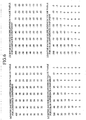
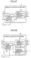
- Fig. 6 shows a maximum value table/minimum value table when inter-encoded mode has a maximum value/minimum value table storage section 2.
- Fig. 7 shows a maximum value table/minimum value table when intra-encoded mode has a maximum value table/minimum value table storage section 2.
- the maximum value/minimum value table storage section 2 pre-stores four types of information in each encoded mode as shown respectively for example in Fig. 6(a) ⁇ (d), Fig. 7(a) ⁇ (d). These four types are a table showing maximum values (hereafter maximum value table) and a table showing minimum values (hereafter minimum value table) based on an encoded mode (intra encoded mode/inter encoded mode) and signal component (luminance component/color difference component).
- Each table as shown in Fig. 6(a) ⁇ (d) and Fig. 7(a) ⁇ (d) has pre-set maximum and minimum values with respect to respective quantization index columns 1a of a block unit (8 pixels x 8 lines).
- the maximum value/minimum value table storage section 2 selects a maximum value table and a minimum value table from the four types of maximum value tables and four types of minimum value tables based on a block encoded mode 1b and a signal component obtained from the block number 1c and outputs the result to the maximum value/minimum value comparison section 3.
- the maximum value/minimum value table storage section 2 selects a maximum value table and a minimum value table for color difference components and inter encoded as shown in Fig. 6(c) and (d) (refer to Fig. 2).
- the selected maximum value table and minimum value table are output to the maximum value/minimum value table comparison section 3.
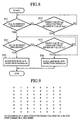
- Fig. 8 is a flowchart showing the processing performed in the maximum value/minimum value table comparison section 3.
- step ST2 When as a result of the comparison in step ST2, the index value (i, j) exceeds the maximum value (i, j) (step ST2 "Yes"), the value "1" is output as an error block detection signal 4a and the operation is completed.
- step ST2 when the comparison process of the index value (i, j) and the maximum value (i, j) is completed with respect to all 64 index numbers and the index value (i, j) does not exceed maximum value (i, j) (step ST1 "Yes"), the comparison is performed in the same way to determine whether or not the index value (i, j) of the quantization index column 1a is less than the maximum value (hereafter maximum value (i, j)) shown by the i th row and j th column of the minimum value table (step ST 3 "No", step ST4).
- the maximum value hereafter maximum value (i, j)
- step ST4 When as a result of the comparison in step ST4, the index value (i, j) is lower than the minimum value (i, j) (step ST4, "Yes"), the value "1" is output as an error block detection signal 4a and the operation is terminated.
- step ST5 When the comparison process of the index value (i, j) and the minimum value (i, j) is completed with respect to all 64 index numbers (step ST3, "Yes"), the value "0" is output as an error block detection signal 4a (step ST5).
- Fig. 9 is an example of inter encoded mode and shows an example of a quantization index column of color difference components. More precisely, Fig. 9 shows an example of a quantization index column of a decoded block unit. However the situation is assumed in which a quantization index column 1a as shown in Fig. 10 is decoded under the influence of errors contained in the encoded bit stream.
- the maximum value table and the minimum value table selected by the maximum value/minimum value table storage section 2 is adapted for inter encoded and color difference components as shown in Fig. 6(c) and (d).
- a quantization index column 1a of a block unit output by the maximum value/minimum value comparison section 3 is output to the switching section 8.
- the switching section 8 switches the output based on an error block detection signal 4a. That is to say, when the error block detection signal 4a is "0", since an error block is shown not to be present, a quantization index column 1a of a block unit is output to the reverse quantization processor 5. On the other hand, when the error block detection signal 4a is "1", since an error block is shown to be present, a quantization index column 1a of block unit is output to the error processor 7.
- the reverse quantization processor 5 performs a reserve quantization process with respect to the quantization index column 1a of the block unit using a quantization step size 1d input from the syntax analysis section 1. Thereafter a DCT coefficient column 1f of the block unit is output to the reverse DCT/decoding image generator 6.
- the reverse DCT/decoding image generator 6 performs a reverse DCT process with respect to the DCT coefficient column 1f of the block unit and generates and outputs a decoded image matching the encoded mode input by the syntax analysis section 1.
- the error processor 7 Since there is an error block, the error processor 7 performs a suppression of error positions based on a fixed method and outputs the generated decoded image when a quantization index column 1a is input from the block unit by the switching section 8.
- block data exists after the macroblock generated by the error and contained in the second GOB, that is to say, a macroblock in a position from a macroblock containing an error-generated block to a macroblock contained up to the analysis of the next unique word.
- Such block data is adapted to be replaced by block data contained in the immediately previous decoded image at the same position as the above block data.
- an image decoding device has a table showing maximum and minimum values which are threshold values corresponding to 64 index values contained in blocks. Since it is determined whether errors are contained in encoded bit streams of data to be decoded by using the maximum and minimum values contained in the table it is possible to perform rapid detection of error blocks matching a fixed syntax. It is also possible to generate decoded images with little influence of errors contained in the encoded bit stream.
- an image decoding device as shown in Fig. 5 was described.
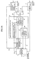
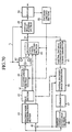
- the image decoding device may be comprised as shown in Fig. 11 and adapted so that the DCT coefficient column if of a block unit output from the reverse quantization processor 5 may be input into the error block detection section 4.
- the quantization index column 1a of the block unit output from the syntax analysis section 1 is such that the DCT coefficient column 1f of the block unit is input into the maximum value/minimum value comparison section 3 of the error block detection section 4 after an reverse quantization process is performed in the reverse processor 5.
- the maximum value / minimum value table storage section 2 has a maximum value table and a minimum value table such as shown in Fig. 12(a) ⁇ (d) and Fig. 13(a) ⁇ (d).
- the DCT coefficient column 1f of the block unit is output by the switching section 8 to the reverse DCT/decoding image generator 6 when the error block detection signal 4a takes a value of "0" and is output to the error processor 7 when the error block detection signal 4a takes a value of "1".
- Embodiment 2 shows another example of an error block detection section shown in embodiment 1. That is to say the error block detection section 4 in embodiment 2 varies the maximum and minimum values which are the threshold values used in the error block detection section 4 in embodiment 1. The values are adapted by a weighted coefficient corresponding to a quantization step size 1d which is threshold value updating information. It is determined whether or not a value of an image signal converted to a frequency band is contained in a range set by the converted maximum and minimum values of the threshold value and in this way the error block is detected.
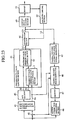
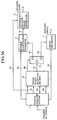
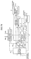
- Fig. 14 is a block diagram showing an image decoding device according to embodiment 2 of the present invention.
- Embodiment 2 comprises a different arrangement from the structure of the image decoding device according to embodiment 1 as shown in Fig. 5.
- 9 is a weighted coefficient determination section which is provided in the error block detection section (error block detection means) 4.
- 1h is a weighted coefficient.
- image data and layer information such as the picture layer, GOB layers, macroblock layer in the encoded bit stream are decoded and analyzed by H. 263 syntax.
- the quantization index column 1a of the obtained block unit (8 pixels x 8 lines) is output to the maximum value/ minimum value comparison section 3.
- the encoded mode (intra encoded mode/ inter encoded mode) 1b is output to the maximum value/ minimum value table storage section 2 and the DCT/decoding image generator 6.
- the block number 1c which is the block position information is output to the maximum value/ minimum value table storage section 2.
- the quantization step size 1d is output to the reverse quantization processor 5 and the weighted coefficient determination section 9.
- an error syntax detection signal 1e is output to the error processor 7 when layer information or image data is analyzed which does not match the H. 263 syntax.
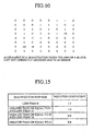
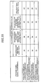
- the weighted coefficient determination section 9 has a table of quantization step size 1d and weighted coefficient 1h as shown in Fig. 15. Using the table, a weighted coefficient 1h which corresponds to the quantization step size 1d used in the reverse quantization process of the block is output to the maximum value/ minimum value comparison section 3.
- the weighted coefficient 1h takes a value of "1.1”
- the weighted coefficient 1h takes a value of "1.0”
- the weighted coefficient 1d takes a value of "0.9”
- the weighted coefficient 1h takes a value of "0.8”.
- the maximum value/ minimum value comparison section 3 reads 64 values in the maximum value table and the 64 values contained in the minimum value table read from in maximum value/ minimum value table storage section 2.
- the maximum value/ minimum value comparison section 3 applies a weighted coefficient 1h from the weighted coefficient determination section 9 to these values and generates a new maximum value table and minimum value table.
- the newly generated maximum value table and minimum value table is shown below.
- the encoded mode is inter encoded
- the block number 1b which is block position information is "5"
- the weighted coefficient 1h is "0.8" (that is to say, the quantization step size is greater than or equal to 24).
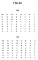
- the newly generated maximum value table and minimum value table as shown in Fig. 16(a), (b) is comprised inter encoded mode as shown in Fig. 6(c) and (d), the 64 values in the maximum value table of the color difference component and the 64 values in the minimum value table respectively multiplied by 0.8.
- the maximum value/ minimum value comparison section 3 in the same way as embodiment 1 performs a comparison to determine whether the index value (i, j) exceeds the maximum value (i, j) shown by the ith row and jth column of the maximum value table updated by the weighted coefficient 1h and performs a comparison to determine whether the index value (i, j) is less than the minimum value (i, j) shown by the ith row and jth column of the minimum value table updated by the weighted coefficient 1h.
- Other operations are the same as the operations described with respect to embodiment 1 and additional description will be omitted.
- the image decoding device varies a maximum value and minimum value, which are threshold values corresponding to 64 index values contained in a block, by varying the values with a weighted coefficient 1h corresponding to a quantization step size 1d.
- the determination is performed as to whether or not an error is contained in the bit stream to be decoded.
- the image decoding device is comprised as shown in Fig. 14.
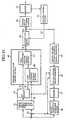
- the device may be comprised as shown in Fig. 17 by inputting a DCT coefficient 1f of the block unit output from the reverse quantization processor 5 into the error block detection section 4.
- the quantization index column 1a of the block unit output from the syntax analysis section 1 is input into the maximum value/minimum value comparison section 3 of the error block detection section 4 after the reverse quantization process is performed in the reverse quantization processor 5.
- the maximum value/minimum value table storage section 2 has a maximum value table and a minimum value table as shown in Fig. 12(a)-(d) and Fig. 13(a)-(d).
- the DCT coefficient column 1f of the block unit is output to the reverse DCT/decoding image generator 6 when the error block detection signal 4a is "0" and is output to the error processor 7 when the error block detection signal 4a is "1".
- the image decoding device varies a maximum value and minimum value, which are threshold values used by the error block detection section 4. by varying the values with a weighted coefficient 1h corresponding to a quantization step size 1d representing threshold value updating information.
- a maximum value and minimum value which are threshold values used by the error block detection section 4.
- the invention is not limited in this respect and depending on encoding conditions such as quantization step size 1d, it is sufficient if threshold value updating information which can update a threshold value is adapted to generate an optimal decoded image.
- threshold value updating information other than a weighted coefficient 1h which corresponds to the quantization step size 1d is sufficient.
- the method of updating of the threshold value need not involve multiplication of the weighted coefficient 1h and may be adapted to update information by addition and subtraction or by a fixed formula.
- an example will be given of an image encoding device which generates an encoded bit stream in which an error contained in the encoded bit stream can be rapidly detected in the image decoding device.
- The is performed by limiting the value of the image signal converted to a frequency band in the image encoding device using maximum and minimum values which are pre-set threshold values.
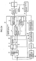
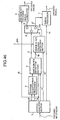
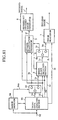
- Fig. 18 is a block diagram of an image encoding device according to embodiment 3 of the present invention.
- 40 is a subtracter
- 41 is an encoded mode determination section
- 42 is a DCT section
- 43 is a encoded data value limiting section (encoded data value limiting means)
- 44 is a quantization section
- 45 is a partial decoded estimation error signal generator
- 46 is a partial decoding image generator
- 47 is a memory
- 49 is a syntax multiplexing section
- 51 is : a buffer
- 52 is an encoded limiting section
- 53 is a maximum value/minimum value control section.
- the encoded data value limiting section 43 is comprised by a maximium value/minimum value storage section 2 and a maximum value/minimum value control section 53.
- An input image is input into the encoded mode determination section 41, the subtracter 40 and the motion correction estimation section 48.
- the motion correction estimation section 48 inputs reference data from the memory 47 and performs block matching using a region of 16 pixels and 16 lines called a macroblock as a unit. In this way, motion information is obtained.
- the motion correction estimation section 48 inputs reference data of a position which corresponds to the motion information from the memory 47 and generates an estimation image.
- the estimation image generated in the motion correction section 48 is output to the partial decoded image generator 46 and the subtracter 40.
- the subtracter 40 generates a differential image from the estimation image and the input image.
- the encoded mode determination section 41 selects an encoded mode (inter/intra) on the macroblock unit with a fixed method determined by H. 263.
- the selected encoded mode 1b is output to the maximum value/minimum value table storage section 2 and the partial decoding image generator 46.
- the DCT section 42 separates the image data of the input macroblock unit into block units and performs DCT processing on the block unit.
- the DCT coefficient column 1f of the block unit is output to the quantization section 44 and the block number 1c is output to the maximum value/minimum value table storage section 2.
- the quantization section 44 uses a quantization step size 1d input from the encoding limiting section 52, performs quantization processing with a fixed method determined by H. 263 and outputs the quantization index column 1a of the block unit to the maximum value/minimum value control section 53.
- the maximum value/minimum value storage section 2 in the same way as embodiment 1 pre-stores four types of maximum value tables and minimum value tables in respective encoded modes as shown in Fig. 6(a)-(d) and Fig. 7(a)-(d).
- respective maximum value tables and minimum value tables are selected from the four types of maximum value tables and minimum value tables respectively shown in Fig. 6(a)-(d) and Fig. 7(a)-(d) based on a signal component obtained from the block number 1c and the encoded mode 1b.
- the result is output to the maximum value/minimum value control section 53.
- Fig. 19 is a flowchart of the process of the maximum value/minimum value control section 53.
- step ST12 "No" the index value (i, j) continues to be used.
- step ST12 When the comparison process of step ST12 is completed with respect to all 64 indexes (step ST11 "Yes"), the comparison is performed as to whether or not the index value (i, j) is lower than a minimum value (i, j) (step ST14, "No", Step ST15).
- Step ST15 When the result of the comparison is that the index value (i, j) is less than a minimum value (i, j) (Step ST15 "Yes"), the index value (i, j) is switched to the minimum value (i, j) (step ST16).
- step ST15 the index value (i, j) continues to he used.
- step ST15 When the comparison process of step ST15 is completed with respect to all 64 indexes (step ST14 "Yes") the routine is completed.
- Fig. 20 shows an example of a quantization index column 1a of a color difference component, inter encoded mode.
- the selected maximum value table and minimum value table are those for color difference and inter encoded mode as shown in Fig. 6(c) and (d).
- the quantization index column 1a output from the maximum value / minimum value control section 53 becomes the quantization index column 1a shown in Fig. 21 in which the value of the 8 th row 1 st column becomes "-5" and the value of the 2 nd row 6 th column becomes "10" from the quantization index column 1a shown in Fig. 20.
- the quantization index column 1a of the block unit processed by the maximum value/minimum value control section 53 is output to the syntax multiplexing unit 49 and the partial decoding estimation error signal generator 45.
- the partial decoding estimation error signal generator 45 performs a reverse DCT process and reverse quantization process on the quantization index column 1a of the input block unit and generates a partial decoding estimation error signal. The result is output to the partial decoding image generator 46.
- the partial decoding image generator 46 operates based on the encoded mode 1b using a macroblock as a unit. That is to say, when the encoded mode 1b is intra, the input partial decoding estimation error signal is read into the memory 47 as a partial decoded image. When the encoded mode is inter, the partial decoding estimation error signal and the estimation image are added and a partial decoded image is generated and read into the memory 47.
- the syntax multiplexing section 49 performs multiplexing and encoding of each layer information, such as a picture layer, GOB layer and macroblock layer, the encoded bit stream according to H. 263 syntax.
- the quantization index column 1a of the block unit which is a two dimensional coefficient column is sequenced transformed to a one dimensional index column by zigzag scanning order.
- Variable length encoding is performed on the sequenced one dimensional index column, the resulting variable length encoding language is multiplexed to an encoded bit stream and the encoded bit stream is output to the buffer 51.
- Fig. 22 shows the sequence of a zigzag scan.
- the zigzag scan is a scanning method which converts a two dimensional signal into a one dimensional signal by scanning in a zigzag towards a coefficient in the lower right from a coefficient in the upper left of the block.
- the buffer 51 in Fig. 18 momentarily stores an input encoded bit stream from the syntax multiplexing section 49 and transmits the encoded bit stream depending on the condition of the transmission pathway from the stored encoded bit stream.
- the buffer remainder which is the capacity of the encoded bit stream stored in the buffer 51 is output to the encoded control section 52.
- the encoded control section 52 performs control of the quantization step size 1d based on the buffer remainder and outputs the updated quantization step size 1d to the quantization section 44.
- the image encoding device has a maximum value and a minimum value which are threshold values corresponding to the 64 index values contained in a block.
- the index value which is generated by the process of encoding is replaced by a maximum value or a minimum value which are threshold values.
- the description was based on an H. 263 encoding method. However even when another encoding method is used which performs orthogonal conversion, it is possible to obtain the same effect. This method may be applied hereafter in the same way to an image encoding device in other embodiments of the present invention.
- an image encoding device is comprised as shown in Fig. 18 and a quantization index column 1a of a block unit is input into the encoded data value control section 43.
- the DCT coefficient column 1f of the block unit output from the DCT section 42 may be input into the encoded data value control section 43.
- the DCT coefficient column 1f of the block unit output from the DCT section 42 is input directly into the maximum value/minimum value control section 53.
- the maximum value/minimum value table storage section 2 has maximum value tables and minimum value tables as shown in Fig. 12(a)-(d) and Fig. 13(a)-(d).
- the DCT coefficient column 1f of the block unit output from the maximum value/minimum value control section 53 is output to the quantization section 44. After a quantization process is performed the quantization index column 1a is output to the syntax multiplexing section 49.
- embodiment 4 another arrangement of the encoded data value limiting section 43 shown in embodiment 3 is given. That is to say, in embodiment 4, the encoded data value limiting section 43 varies a maximum value and minimum value, which are pre-set threshold values, by adapting the values with a quantization step size 1d.
- the image encoding device can generate an encoded bit stream which can detect errors contained in an encoded bit stream rapidly.
- Fig. 24 is a block diagram of an image encoding device according to a fourth embodiment of the present invention.
- embodiment 4 an arrangement which differs from the image encoding device shown in Fig. 18 will be described.
- Fig. 24, 9 is a weighted coefficient determination section provided in the encoded data value limiting section (encoded data value limiting means) 43.
- the encoding control section 52 performs control of the quantization step size 1d based on a buffer remainder and outputs the updated quantization step size 1d to the weighted coefficient determination section 9 of the quantization section 44 and the encoded data value limiting section 43.
- the weighted coefficient determination section 9 has a table of quantization step sizes 1d and weighted coefficients 1h as shown in Fig. 15 described with reference to embodiment 2.
- the table is used to determine a weighted coefficient 1h which corresponds to a quantization step size 1d used in the reverse quantization process of the block.
- the determined weighted coefficient 1h is output to the maximum value/minimum value control section 53.
- the weighted coefficient 1h takes a value of "1.1”
- the weighted coefficient 1h takes a value of "1.0”
- the weighted coefficient 1h takes a value of "0.9”
- the weighted coefficient 1h takes a value of "0.8”.
- the maximum value/ minimum value control section 53 applies a weighted coefficient 1h to the 64 values in the maximum value table and the 64; values contained in the minimum value table selected and read from the maximum value/ minimum value table storage section 2 and generates an updated maximum value table and minimum value table.
- the updated maximum value table and minimum value table are as shown in Fig. 16(a), (b) described with reference to embodiment 2.
- the encoded mode is inter encoded
- the block number 1c of the block is "5"
- the weighted coefficient 1h is "0.8" (that is to say, the quantization step size 1d is greater than or equal to 24).
- the updated maximum value table and minimum value table is as shown in Fig. 16(a), (b) and, in the inter encoded mode as shown in Fig. 6(c), (d), is comprised of 64 values in the maximum value table of the color difference component and 64 values in the minimum value table respectively multiplied by 0.8.
- the maximum value/ minimum value control section 53 in the same way as embodiment 3, in the order as shown in Fig. 19, performs a comparison to determine whether the index value (i, j) exceeds the maximum value (i, j) shown by the ith row and jth column of the maximum value table updated by the weighted coefficient 1h and performs a comparison to determine whether the index value (i, j) is less than the minimum value (i, j) shown by the ith row and jth column of the minimum value table updated by the weighted coefficient 1h in the same way.
- the encoded mode is inter
- the color difference component and the weighted coefficient 1h is "0.8" (the quantization step size 1d is greater than or equal to 24)
- the quantization index column 1a of the block unit is as shown in Fig. 20.
- the generated maximum value table, and the minimum value table apply the value 0.8 to each coefficient for color difference and inter encoded mode in Fig. 6(c) and (d) and the maximum value table and the minimum value table are as shown in Fig. 16(a) and (b) described with reference to embodiment 2.
- the quantization index column 1a output from the maximum value / minimum value control section 53 becomes the quantization index column 1a shown in Fig. 25 in which the index value of the 8 th row 1 st column becomes "-4" and the index value of the 2 nd row 6 th column becomes "8" of the values in the quantization index column 1a shown in Fig. 20.
- the image encoding device updates maximum values and minimum values which are threshold values corresponding to the 64 index values contained in a block.
- the values are updated by a quantization step size 1d.
- an index value which is greater than an updated maximum value exists, or when an index value which is lower than an updated minimum value exists the index value which is generated by the process of encoding is replaced using the respective threshold values.
- an image encoding device is comprised as shown in Fig. 24 and a quantization index column 1a of a block unit is input into the encoded data value control section 43.
- the DCT coefficient column 1f of the block unit output from the DCT section 42 may be input into the encoded data value limiting section 43.
- the DCT coefficient column 1f of the block unit output from the DCT section 42 is input directly into the maximum value/minimum value control section 53 of the encoded data value limiting section 43.
- the maximum value/minimum value table storage section 2 has maximum value tables and minimum value tables as shown in Fig. 12(a)-(d) and Fig. 13(a)-(d).
- the DCT coefficient column 1f of the block unit output from the maximum value/minimum value control section 53 is input to the quantization section 44. After a quantization process is performed in the quantization section 44, the quantization index column 1a is output to the syntax multiplexing section 49.
- an error block detection section 4 shown in embodiment 1 another arrangement of an error block detection section 4 shown in embodiment 1 is shown. That is to say, in embodiment 5, an example is given of an image decoding device which detects errors on a block unit which are generated in an encoded bit stream generated by H. 263 video compression encoding. This is performed by the position of the last valid coefficient (a non-zero coefficient) when scanning an image signal list of a block unit in zigzag scanning order in an image signal list of a block unit in a frequency band.
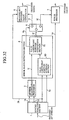
- Fig. 27 is a block diagram of an image decoding device according to a fifth embodiment of the present invention.
- the structure of the image decoding device according to a fifth embodiment differs when compared with the structure of the image decoding device according to a first embodiment only in that an error block detection section (error block detection means) is provided.
- error block detection section 4 will be described below.
- 80 is a valid coefficient position storage section
- 81 is a valid coefficient position comparison section.
- the encoded bit stream is input into the syntax analysis section 1 and analysis and decoding of image data and layer information such as the picture layer, GOB layer, macroblock layer is performed by H. 263 syntax.
- the quantization index column 1a of the obtained block unit (8 pixels x 8 lines) is output to the valid coefficient position comparison section 81.
- the encoded mode (intra encoded mode/ inter encoded mode) 1b is output to the valid coefficient position storage section 80 and the reverse DCT/decoding image generator 6.
- the block number 1c which is block position information is output to the valid coefficient position storage section 80.
- the quantization step size 1d is output to the reverse quantization processor 5.
- an error syntax detection signal 1e is output to the error processor 7 when layer information or image data is analyzed which does not match the H. 263 syntax.
- the valid coefficient position storage section 80 as shown in Fig. 28 stores a threshold value (hereafter valid coefficient threshold value) which gives a range of frequencies of an image signal list in a frequency based on a signal component (color difference component/ luminance component) and the encoded mode 1b. A corresponding valid coefficient threshold value is selected and output based on the signal component obtained from the block number 1c and the encoded mode of the block.
- a threshold value hereafter valid coefficient threshold value
- a threshold value which gives the range of frequencies of the image signal list in the frequency band is precisely the value showing at what position the last existing valid coefficient is placed counted from the position of the coefficient of the linear flow component when the block is scanned with zigzag scanning order.
- the valid coefficient position storage section 80 selects the valid coefficient threshold value "21" for the color difference component and inter encoded mode based on the encoded mode 1b and the block number 1c and outputs the result to the valid coefficient position comparison section 81.
- Fig. 29 is a flowchart of the process of the valid coefficient position comparison section 81.
- the valid coefficient position comparison section 81 calculates a position (hereafter coef_loc) of the last valid coefficient existing in the highest frequency component in a quantization index column 1a of a block unit scanned in zigzag order (step ST21).
- the calculated coef_loc is then compared with a valid coefficient threshold value output from the valid coefficient position storage section 80 (step ST22).
- step ST22 "Yes” When it is found that coef_loc is greater than the valid coefficient threshold value as a result of the comparison, (step ST22 “Yes”), a value “1” is output as an error block detection signal 4a (step ST23). On the other hand, in other cases, (step ST22 “No”), a value "0" is output as an error block detection signal 4a (step ST24).
- Fig. 30 shows an example of a quantization index column 1a for color difference and inter encoded mode.
- the quantization index column 1a shown in Fig. 30 is considered to be decoded into the quantization index column 1a shown in Fig. 31 by the influence of an error contained in the encoded bit stream.
- the encoded bit stream in the encoded bit stream, the situation is assumed that after an encoding language showing the 5 th row and 1 st column index, the sequence "0001101010" (the quantization index column 1a shown in Fig. 30 analyzes this encoded bit stream) becomes the encoded bit stream "0000101010" (the quantization index column 1a shown in Fig. 31 analyzes this encoded bit stream) with an error generated in the 4 th bit.
- the valid coefficient threshold value selected by the valid coefficient position storage section 80 is "21" for color difference and inter-encoded (refer to Fig. 28).
- the position of the last valid coefficient in the zigzag order in the quantization index column 1a block unit decoded by an encoded bit stream containing an error is the 4 th row 5 th column as shown in Fig. 31. This position is "32" which corresponds to the 32 nd value of Fig. 22.
- the valid coefficient position comparison section 81 Since the result of the comparison performed by the valid coefficient position comparison section 81 shows that the position "32" of the last valid coefficient in zigzag scanning order in the quantization index column 1a of the block unit decoded by the encoded bit stream containing an error is greater than the valid coefficient threshold value "21", the value "1" is output to the switching section 8 as an error block detection signal 4a.
- the switching section 8 outputs the quantization index column 1a of the block unit to the reverse quantization processor 5 when the error block detection signal 4a from the valid coefficient comparison section 81 has a value of "0".
- the switching section 8 outputs the quantization index column 1a of the block unit to the error processor 7 when the error block detection signal 4a has a value of "1".
- the image decoding device has a valid coefficient threshold value which is a threshold value which defines a range of frequencies of an image signal column in a frequency band. It is determined whether or not an error is contained in a bit stream of data to be decoded based on the valid coefficient threshold value and the position of the lasting existing valid coefficient existing in zigzag scanning order. Thus it is possible to perform rapid detection of an error block which matches a fixed syntax. It is also possible to generate a decoded image with little influence of errors contained in an encoded bit stream.
- an image decoding device as shown in Fig. 27 was described.
- the image decoding device may be comprised as shown in Fig. 32 and adapted so that the DCT coefficient column 1f of a block unit output from the reverse quantization processor 5 may be input into the error block detection section 4.
- the quantization index column 1a of the block unit output from the syntax analysis section 1 is input into the reverse quantization processor 5 and after a reverse quantization process is performed in the reverse quantization processor 5, it is input into the valid coefficient comparison section 81 of the error block detection section 4.
- the DCT coefficient column 1f of the block unit is output by, the switching section 8 to the reverse DCT/decoding image generator 6 when the error block detection signal 4a takes a value of "0" and is output to the error processor 7 when the error block detection signal 4a takes a value of "1".
- Embodiment 6 comprises another arrangement of the error block detection section 4 shown with reference to embodiment 5.
- the error block detection section 4 in embodiment 6 converts a valid coefficient threshold value used in the error block detection section 4 of embodiment 5 by the quantization step size 1d and detects errors generated in an encoded bit stream generated by H.263 video compression encoding in a block unit. Detection is performed by the position of the last valid coefficient when scanning an image signal column of a block unit in a zigzag scanning order in an image signal column of a block unit in a frequency band.
- Fig. 33 is a block diagram of an image decoding device according to embodiment 6 of the present invention.
- the structure of the image decoding device according to embodiment 6 only differs from that described with reference to embodiment 5 as regards the error block detection section (error block detection means) 4.
- the error block detection section 4 will be described.
- 9 is a weighted coefficient determination section provided in an error block detection section 4.
- 1h is a weighted coefficient.
- the encoded bit stream is input into the syntax analysis section 1 and analysis and decoding of the image data and each layer information of the picture layer, GOB layer, macroblock layer are performed according to H. 263 syntax.
- a quantization index column 1a of the obtained block unit (8 pixels x 8 lines) is output to the valid coefficient position comparison section 81.
- An encoded mode 1b (intra encoded mode/inter encoded mode) is output to the valid coefficient position storage section 80 and the reverse DCT/decoding image generator 6.
- a block number 1c which represents block position information is output to the valid coefficient position storage section 80.
- a quantization step size 1d is output to the reverse quantization processor 5 and the weighted coefficient determination section 9.
- an error syntax detection signal 1e is output to the error processor 7 to that effect.
- the weighted coefficient determination section 9 has a corresponding table of quantization step size 1d and weighted coefficients 1h as shown in Fig. 34.
- a weighted coefficient 1h corresponding to a quantization step size 1d used in reverse quantization processing of a block is determined using the table.
- the determined weighted coefficient 1h is output to the valid coefficient position comparison section 81.
- the weighted coefficient 1h is determined and output as the value "1.1”. If the quantization step size 1d is greater than or equal to "8" and less than "16", the weighted coefficient 1h is determined and output as the value "1.0”. If the quantization step size 1d is greater than or equal to 16 and less than "24", the weighted coefficient 1h is determined and output as the value "0.9”. If the quantization step size 1d is greater than or equal to "24", the weighted coefficient 1h is determined and output as the value "0.8".
- the valid coefficient position comparison section 81 calculates the multiple of a valid coefficient threshold value selected and output from the valid coefficient position storage section 80 and a weighted coefficient 1h from the weighted coefficient determination section 9.
- Fig. 35 shows an example of a valid coefficient threshold value updated and generated using a valid coefficient threshold value and a weighted coefficient 1h in the valid coefficient position comparison section 81 of embodiment 6.
- Values of the valid coefficient threshold value when the quantization step size is greater than or equal to "8" and less than "16" (weighted coefficient 1h is "1.0") are used as values shown in Fig. 28 described with respect to embodiment 5.
- the valid coefficient position comparison section 81 calculates a position (hereafter coef_loc) of the last valid coefficient existing in a quantization index column 1a of a block unit scanned in zigzag order. The calculated coef_loc is then compared with a valid coefficient threshold value corrected by a weighted coefficient 1h.
- the valid coefficient position comparison section 81 When it is found that coef_loc is greater than the valid coefficient threshold value corrected by the weighted coefficient 1h as a result of the comparison, the valid coefficient position comparison section 81 outputs a value "1" to the switching section 8 as an error block detection signal 4a. On the other hand. in other cases, a value "0" is output as an error block detection signal 4a to the switching section 8.
- the switching section 8 outputs the quantization index column 1a of the block unit to the reverse quantization processor 5 when the error block detection signal 4a has a value of "0".
- the switching section 8 outputs the quantization index column 1a of the block unit to the error processor 7 when the error block detection signal 4a has a value of "1".
- the image decoding device varies a valid coefficient threshold value with a quantization step size 1d.
- the quantization step size 1d of the unit block it is determined whether or not an error is contained in a bit stream of data to be decoded by use of the valid coefficient threshold value varied by the quantization step size 1d and the position of the last calculated valid coefficient existing in a zigzag scanning sequence.
- an image decoding device as shown in Fig. 33 was described.
- the image decoding device may be comprised as shown in Fig. 36 and adapted so that the DCT coefficient column 1f of a block unit output from the reverse quantization processor 5 may be input into the error block detection section 4.
- the quantization index column 1a of the block unit output from the syntax analysis section 1 is such that the DCT coefficient column 1f of the block unit is input into the valid coefficient comparison section 81 after a reverse quantization process is performed in the reverse quantization processor 5.
- the DCT coefficient column 1f of the block unit is output by the switching section 8 to the reverse DCT/decoding image generator 6 when the error block detection signal 4a takes a value of "0" and is output to the error processor 7 when the error block detection signal 4a takes a value of "1".
- Embodiment 7 comprises another arrangement of the encoded data value limiting section 43 shown with reference to embodiment 3.
- the encoded data value limiting section 43 in embodiment 7 pre-sets a valid coefficient value and, with respect to coefficients contained in image signal columns in block units in frequency bands, replaces valid coefficients existing in a band exceeding the valid coefficient value in zigzag scanning order with an invalid coefficient (a coefficient with a non-zero value).
- an invalid coefficient a coefficient with a non-zero value
- Fig. 37 is a block diagram of an image encoding device according to embodiment 7 of the present invention.
- the structure of the image decoding device according to embodiment 7 only differs from that described with reference to embodiment 3 in Fig. 18 as regards the encoded data value limiting section 43 (encoded data value limiting means).
- the encoded data value limiting section 43 will be described.
- 80 is a valid coefficient position storage section and 82 is a valid coefficient position control section.
- a valid coefficient threshold value is pre-set and stored in the valid coefficient position storage section 80 based on the signal component (luminance component/color difference component) and the encoded mode 1b shown in Fin. 28 with respect to embodiment 5.
- a respective valid coefficient threshold value is selected by the signal component obtained by the block number 1c and the encoded mode 1b of the block.
- the valid coefficient position storage section 80 selects the valid coefficient threshold value "21" for inter-encoded and color difference.
- the selected valid coefficient threshold value "21" is output to the valid coefficient position control section 82.
- Fig. 38 shows the processing performed by the valid coefficient position control section 82.
- the valid coefficient position control section 82 scans the index contained in the quantization index column 1a in zigzag order. When the scanned index position exceeds the position shown by the valid coefficient threshold value (step ST31 "No", step ST32 "Yes"), the index value is made to take the value of zero (step ST33). In other cases, the process is terminated in this state.
- the quantization index column 1a of the block unit is output to the partial decoding estimation error signal generator 45 and the index multiplexing section 49.
- the quantization index column 1a shown in Fig. 39 is input into the valid coefficient position control section 82 and the valid coefficient threshold value has the value of "21".
- a valid coefficient exists at the 2 nd , 3 rd and 23 rd position counting in zigzag scanning order on the quantization index column 1a shown in Fig. 39. Since the assumed valid coefficient threshold value has the value "21”, the index existing at a position which exceeds the valid coefficient threshold value "21" is replaced with the value zero. That is to say, the index value existing at a 23 rd position on the quantization index column 1a shown in Fig. 39 takes the value zero.
- the quantization index column 1a output by the valid coefficient position control section 82 is as shown in Fig. 40.
- the image encoding device has a threshold value defining the range of frequencies of an image signal list in a frequency band.
- a valid coefficient exists in a band exceeding the threshold value in zigzag scanning order, the value of the valid coefficient generated by the process of encoding is replaced by the value zero.
- an image encoding device as shown in Fig. 37 was described in which a quantization bit stream column 1a of a block unit is input into an encoded data value limiting section 43.
- the image encoding device may be comprised as shown in Fig. 41 and adapted so that the DCT coefficient column 1f of a block unit may be input into the encoded data value limiting section 43.
- the DCT coefficient column 1f of the block unit output from the DCT section 42 is input into the valid coefficient control section 82.
- the DCT coefficient column 1f of the block unit output from the valid coefficient position control section 82 is output to the quantization section 44.
- Embodiment 8 comprises another arrangement of the encoded data value limiting section 43 shown with reference to embodiment 7. That is to say in embodiment 8, a pre-set valid coefficient value is varied by a quantization step size 1d. With respect to coefficients contained in image signal columns in block units in a frequency band, valid coefficients existing in a band exceeding the valid coefficient value in zigzag scanning order are replaced with an invalid coefficient (a coefficient with a non-zero value). Thus it is possible to generate an encoded bit stream which allows rapid detection of errors in the image decoding device.
- Fig. 42 is a block diagram of an image encoding device according to embodiment 8 of the present invention.
- the structure of the image encoding device according to embodiment 8 only differs from that described with reference to embodiment 7 in Fig. 37 as regards the encoded data value limiting section 43 (encoded data value limiting means).
- the encoded data value limiting section 43 will be described below.
- 9 is a weighted coefficient determination section provided in the encoded data value limiting section 43 and 1h is a weighted coefficient.
- Control of the quantization step size 1d is performed in the encoded control section 52 based on a buffer remainder and the updated quantization step size 1d is output to the quantization section 44 and the weighted coefficient determination section 9.
- the weighted coefficient determination section 9 has a table of quantization step size 1d and weighted coefficients 1h as shown in Fig. 34.
- a weighted coefficient 1h corresponding to a quantization step size 1d used in reverse quantization processing of the block is determined using the table.
- the determined weighted coefficient 1h is output to the valid coefficient position control section 82.
- the weighted coefficient 1h is determined and output as the value "1.1”. If the quantization step size 1d is greater than or equal to "8" and less than "16", the weighted coefficient 1h is determined and output as the value "1.0”. If the quantization step size 1d is greater than or equal to "16" and less than "24", the weighted coefficient 1h is determined and output as the value "0.9”. If the quantization step size 1d is grearer than or equal to "24” the weighted coefficient 1h is determined and output as the value "0.8".
- the valid coefficient position control section 82 calculates a multiple of a valid coefficient threshold value selected and output from the valid coefficient position storage section 80 and a weighted coefficient 1h and generates an updated valid coefficient threshold value.
- the updated valid coefficient threshold value generated using the weighted coefficient 1h and valid coefficient threshold value is as shown in Fig. 35 with respect to embodiment 6.
- the valid coefficient position control section 82 scans an index contained in a quantization index column 1a in zigzag order. When the position of the scanned index is greater than the position shown for the updated valid coefficient threshold value, the index value is reset to the value zero and is output to the partial decoding estimation error signal generator 45 and the syntax multiplexing section 49.
- the image encoding device has a threshold value which shows the position of the last valid coefficient in zigzag scanning order
- the threshold value is updated by the quantization step size 1d and when a valid coefficient exists in a band which exceeds the updated threshold value in zigzag scanning order, the valid coefficient generated by the process of encoding is replaced by a value of zero.
- an image encoding device as shown in Fig. 42 was described in which a quantization bit stream 1a of the block unit is input into the encoded data value limiting section 43.
- the image encoding device may be comprised as shown in Fig. 43 and adapted so that the DCT coefficient column 1f of a block unit may be input into the encoded data value limiting section 43.
- the DCT coefficient column 1f of the block unit output from the valid coefficient position control section 82 is output to the quantization section 44.
- Embodiment 9 comprises another arrangement of the image decoding device according to embodiment 1, embodiment 2, embodiment 5 and embodiment 6. That is to say, in embodiment 9, error detection taking a block as a unit is performed based on a threshold value and an image signal in a frequency band. Error detection using a block column (in embodiment 9, it is assumed that GOB is an example of a unity containing at least one or more blocks) based on a threshold value which is different from the threshold value above and an error detection state taking the obtained block as a unit. Then it is determined whether or not the error is contained in the GOB.
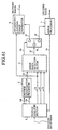
- Fig. 44 is a block diagram of an image decoding device according to a first embodiment of the present invention.
- reference numeral 10 is an error block column detection section (block column detection means)
- 10a is an error block column detection section
- 10b is an error determination threshold value.
- Other components have been described above and are denoted by the same reference numerals and thus additional description will be omitted.
- the error block detection section (error block detection means) 4 may be comprised by the error block detection section 4 as shown with reference to any of embodiment 1, embodiment 2, embodiment 5 and embodiment 6.
- An encoded bit stream is input into a syntax analysis section 1 and analysis and decoding of the image data and all layer information such as picture layer.
- GOB layer, and macroblock layer is performed by H. 263 syntax.
- the quantization index column 1a of the obtained block unit (8 pixels x 8 lines), an encoded mode (intra encoded mode/inter encoded mode) 1b and a block number 1c which represents block position information are output to the error block detection section 4.
- a quantization step size 1d is output to the reverse quantization processor 5 and the encoded mode 1b is output to the reverse DCT/decoding image generator 6.
- an error syntax detection signal 1e is output to the error processor 7 to that effect.
- the GOB number 1g which shows block column units is output to the error block column detection section 10 by the syntax analysis section 1.
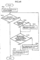
- Fig. 45 is a flowchart showing the processing performed in the error block column detection section 10.
- the error block column detection section 10 determines whether or not a block is a block contained at the GOB header based on the GOB number 1g input from the syntax analysis section 1. When the determination is performed, the error block count number is initialized (step ST41).
- step ST42 The determination is performed as to whether the input error block detection signal 4a is "1" (step ST42 "No", step ST43) and only when it is determined that the value is "1" (step ST43 "Yes"), the error block count number is incremented by 1 (step ST44). Thus when the error block detection signal 4a is "0" (step ST43 "No"), the error block count number is not incremented by step ST44.
- step ST45 the comparison of the error block count number and the externally set error determination threshold value 10b is performed (step ST45).
- the value "0" is output to the switching section 8 as an error block column detection signal 10a (step ST46).
- step ST45 "Yes" the value "1' is output to the switching section 8 as an error block column detection signal 10a (step ST47).
- step ST42 ⁇ step ST 47 is performed with respect to all blocks contained in the GOB while referring to the GOB number 1g input from the syntax analysis section 1.
- the switching section 8 outputs a quantization index column 1a of block unit to the reverse quantization processor 5 when the error block column detection signal 10a is "0". On the other hand, when the error block column detection signal is "1", the switching section 8 outputs a quantization index column 1a of the block unit to the error processor 7.
- the determination as to whether errors are contained in an encoded bit stream which is to be decoded is performed twice in an error block column detection section 10 and an error block detection section 4 of the image decoding device.
- error determination is performed which determines that errors are contained in blocks which actually do not contain errors. It is also possible to generate a decoded image with little influence of errors contained in encoded bit streams.
- the image decoding device was comprised as shown in Fig. 44.
- the device may be comprised as shown in Fig. 46 and adapted so that the DCT coefficient column 1f of a block unit on which a reverse quantization process is performed in the reverse quantization processor 5 may be input into the error block detection section 4.
- embodiment 10 another arrangement of the syntax multiplexing section 49 shown in embodiment 4 or embodiment 8 is shown. That is to say, in embodiment 10, an example is given of an image encoding device which generates an encoded bit stream which allows the rapid detection of errors contained in an encoded bit stream in an image decoding device by multiplexing a weighted coefficient 1h used in an encoded data value limiting section 43 into an encoded bit stream as header information.
- Fig. 47 is a block diagram of an image encoding device according to a tenth embodiment of the present invention. As shown in Fig. 47, all components of the image encoding device according to embodiment 10 are the same as those components as shown in embodiment 4 in Fig. 24 or embodiment 8 in Fig. 42 and are designated by the same numerals. Thus additional description will be omitted.
- the encoded data value limiting section 43 in Fig. 47 may be comprised as shown in Fig. 48 for example, in the same way as the encoded data value limiting section 43 of the image encoding device in embodiment 4 in Fig. 24 or Fig. 26. Otherwise it may be comprised as shown in Fig. 49 for example, in the same way as the encoded data value limiting section 43 of the image encoding device in embodiment 8 in Fig. 42 or Fig. 43.
- the weighted coefficient 1h is determined in the same way as embodiment 4 or embodiment 8 in the weighted coefficient determination section 9 of the encoded data value limiting section 43.
- the determined weighted coefficient 1h is output not only to the valid coefficient position control section 82 and the maximum value/minimum value control section 53 but also to the syntax multiplexing section (multiplexing means) 49.
- Fig. 50 is a block diagram of a syntax multiplexing section 49 and describes the situation in which an encoding language for a weighted coefficient 1h is multiplexed by the picture layer multiplexing section.
- 60 is a picture layer multiplexing section
- 61 is a GOB layer multiplexing section
- 62 is a macroblock layer multiplexing section
- 63 block data multiplexing section.
- Fig. 51 shows the relationship of weighted coefficient 1h and the encoded language which corresponds to each weighted coefficient 1h in embodiment 10. For example, if the weighted coefficient 1h has a value of "0.8", the value "110" is multiplexed as an encoded language. If the weighted coefficient 1h has a value of "0.9”, the value “10” is multiplexed as an encoded language. If the weighted coefficient 1h has a value of "1.0”, the value “1” is multiplexed as an encoded language. If the weighted coefficient 1h has a value of "1.1”, the value "11” is multiplexed as an encoded language.
- the encoded bit stream with multiplexed encoding language with respect to the weighted coefficient 1h, the picture layer information, picture start code (PSC) in the picture layer multiplexing section 60 are input into the GOB layer multiplexing section 61.
- the GOB layer multiplexing section 61 multiplexes the GOB start code (GBSC) showing the start of the GOB layer information and the GOB layer information and inputs the result into the macroblock layer multiplexing section 62.
- GBC GOB start code
- the macroblock layer multiplexing section 62 multiplexes the macroblock (MB) layer information in the encoded bit stream input from the GOB layer multiplexing section 61 and outputs the result to the block data multiplexing section 63.
- MB macroblock
- the quantization index column 1a which is a two dimensional block unit is transformed into a one dimensional quantization index column 1a by a zigzag scan order (refer to Fig. 22).
- Variable length encoding is performed on the one dimensional quantization index column 1a and using the obtained variable length encoding language as block data, the encoded bit stream is multiplexed. Thereafter the encoded bit stream is output to the buffer 51.
- the encoded bit stream output from the syntax multiplexing section 49 as shown above is shown by example in Fig. 52.
- Fig. 53 is a block diagram of another arrangement of the syntax multiplexing section 49.
- the arrangement shown in Fig. 53 differs from that shown in Fig. 50 in that the encoding language of the weighted coefficient 1h is not multiplexed by the picture layer multiplexing section 60 and is multiplexed by the GOB layer multiplexing section 61.
- the picture layer multiplexing section 60 multiplexes the picture layer start code (PSC), showing the start of the picture layer information, and the picture layer information and outputs the result into the GOB layer multiplexing section 61.
- PSC picture layer start code
- the GOB layer multiplexing section 61 multiplexes the GOB start code (GBSC) showing the start of the GOB layer information, the encoding language which corresponds to the weighted coefficient 1h input from the weighted coefficient determination section 9 and the GOB layer.
- GBC GOB start code
- the weighted coefficient 1h is encoded using the table shown in Fig. 51 as described above and is multiplexed to the encoded bit stream as weighted coefficient information.
- the operation of the macroblock layer multiplexing section 62 and the block data multiplexing section 63 is the same as that described above with reference to Fig. 50 and thus additional description will be omitted.
- the encoded bit stream output from the syntax multiplexing section 49 is show for example in Fig. 54.
- the image encoding device multiplexes a weighted coefficient 1h used in an encoded data value limiting section 43 as threshold value updating information to an encoded bit stream as a section of header information.
- an image encoding device is comprised as shown in Fig. 47 and a quantization index column 1a of a block unit is input into the encoded data value control section 43.
- the DCT coefficient column 1f of the block unit may be input into the encoded data value limiting section 43.
- the DCT coefficient column 1f of the block unit output from the DCT section 42 is into the encoded data value control section 43.
- the encoded data value control section 43 may be comprised as shown in Fig. 48 as shown above or may be comprised as shown in Fig. 49.
- the maximum value / minimum value table storage section 2 shown in Fig. 48 has a maximum value table and a minimum value table such as shown in Fig. 12(a) ⁇ (d) and Fig. 13(a) ⁇ (d).
- the DCT coefficient column 1f of the block unit output from the encoded data value control section 43 is output to the quantization section 44.
- embodiment 11 another arrangement of the syntax analysis section 1 shown in embodiment 2 or embodiment 6 is shown. That is to say, in embodiment 11, an example is given of performing analysis of weighted coefficient information used in an error block detection section 4 by an encoded bit stream which is generated by the image encoding device in embodiment 10.
- Fig. 56 is a block diagram of the overall structure of an image decoding device according to embodiment 11 of the present invention. As shown in Fig. 56, since the structure of the image decoding device according to embodiment 11 is the same as those components as shown in embodiment 2 in Fig. 14 or embodiment 6 in Fig. 33, components are designated by the same numerals. Thus additional description will be omitted.
- the error block detection section (error block detection means) 4 in embodiment 11 may be comprised as shown in Fig. 57 for example, from a maximum value/minimum value table storage section 2 and a maximum value/minimum value table comparison section 3. Otherwise as shown in Fig. 58, it may be comprised of a valid coefficient position storage section 80 and a valid coefficient position comparison section 81.
- the error block detection section 4 in embodiment 11 comprises the weighted coefficient determination section 9 removed from the error block detection section 4 of embodiment 2 as shown in Fig. 14 or from the error block detection section 4 in embodiment 6 as shown in Fig. 33.
- the maximum value/minimum value comparison section 3 shown in Fig. 57 and the valid coefficient position comparison section 81 shown in Fig. 58 perform processing using a weighted coefficient 1h input from the syntax analysis section 1.
- Fig. 59 is a block diagram showing the structure of a syntax analysis section 1 in embodiment 11. Analysis is performed of multiplexed weighted coefficient information in a picture layer.
- 71 denotes a start code analysis section
- 72 is a picture layer analysis section
- 73 is a GOB layer analysis section
- 74 is a macroblock layer analysis section
- 75 is a block data analysis section.
- the start code analysis section 71 performs analysis of a start code contained in an input encoded bit stream. If the analyzed start code shows a picture layer, the encoded bit stream is output to the picture layer analysis section 72. If the analyzed start code shows a GOB layer, the encoded bit stream is output to the GOB layer analysis section 73. When a start code is analyzed which does not match a fixed syntax, an error syntax detection signal 1e is output to the error processor 7 to that effect.
- Analysis of the weighted coefficient information and the picture layer information is performed by the input encoded bit stream in the picture layer analysis section 72.
- the analyzed encoded bit stream is output to the start code analysis section 71.
- the decoded weighted coefficient 1h is output to the error block detection section 4.
- Analysis of the GOB layer information is performed in the GOB layer analysis section 73 and the analyzed encoded bit stream is output to the macroblock layer analysis section 74.
- Analysis of the macroblock layer information is performed in the macroblock layer analysis section 74 and the analyzed encoded bit stream is output to the block data analysis section 75.
- the encoded mode 1b contained in the analyzed macroblock layer is output to the error block detection section 4 and the quantization step size 1d is output to the reverse quantization processor 5.
- the block data analysis section 75 performs analysis of block data information and outputs the analyzed encoded bit stream to the start code analysis section 71.
- Quantization index column 1a contained as block data information and the block number 1c are output to the error block detection section 4.
- an error syntax detection signal 1e is output to the error processor 7 to that effect.
- Fig. 60 is a block diagram of another arrangement of the syntax analysis section 1 shown in embodiment 11 and shows the situation in which multiplexed weighted coefficient information is analyzed in the GOB layer.
- the start code analysis section 71 analyzes the start code which is contained in the input encoded bit stream.
- an encoded bit stream is output to the picture layer analysis section 72 and when the analyzed start code shows a GOB layer, an encoded bit stream is output to the GOB layer analysis section 73.
- the picture layer analysis section 72 analyzes picture layer information by the input encoded bit stream and outputs the analyzed encoded bit stream to the start code analysis section 71.
- the GOB layer analysis section 73 performs analysis of the weighted coefficient and the GOB layer information and outputs the analyzed encoded bit stream to the picture layer analysis section 74.
- the decoded weighted coefficient 1h is output to the error block detection section 4.
- an error syntax detection signal 1e is output to the error processor 7 to that effect.
- the image decoding device performs decoding and analysis of weighted coefficient information as threshold value updating information from an encoded bit stream and updates a threshold value used in obtained weighted coefficient 1h. It is determined whether or not an error is contained in an encoded bit stream to be decoded based on the updated threshold value.
- an image decoding device is comprised as shown in, Fig. 56. However as shown in Fig. 61, the DCT coefficient column 1f of the block unit output from the reverse quantization processor 5 may be input into the error block detection section 4.
- the error block detection section 4 may be comprised as shown in Fig. 57 as shown above or may he comprised as shown in Fig. 58.
- the maximum value / minimum value table storage section 2 shown in Fig. 57 has a maximum value table and a minimum value table such as shown of the error block detection section 4 in Fig. 12(a) ⁇ (d) and Fig. 13(a) ⁇ (d).
- the DCT coefficient column 1f of the block unit is output to the reverse DCT/decoding image generator 6 when the error block detection signal 4a is "0" by the switching section 8 and is output to the error processor 7 when the error block detection signal 4a is "1".
- embodiment 12 another arrangement of the syntax multiplexing section as shown in embodiment 7 or embodiment 8 is shown. That is to say, in embodiment 12, an example is given of an image encoding device which generates an encoded bit stream which allows the rapid detection of errors contained in an encoded bit stream in an image decoding device by the multiplexing of a valid coefficient threshold value used in an encoded data value limiting section 43 to an encoded bit stream as a header information.
- Fig. 62 is a block diagram of the overall structure of an image encoding device according to embodiment 12 of the present invention.
- the structure of the image encoding device according to embodiment 12 may be the same as those components as shown in embodiment 7 in Fig. 37 or embodiment 8 in Fig. 42. Thus similar components are designated by the same numerals and additional description will be omitted.
- the encoded data value limiting section 43 (encoded data value limiting means) in embodiment 12 may be comprised as shown in Fig. 41 for example, from an encoded data value limiting section 43 as in embodiment 7. Otherwise as shown in Fig. 42, it may be comprised of the encoded data value limiting section 43 as shown in embodiment 8.
- the valid coefficient position storage section 80 contained in the encoded data value limiting section 43 outputs the four types of valid coefficient threshold value 1i in the valid coefficient position storage section 80 to the syntax multiplexing section (multiplexing means) 49 in operations other than those described with respect to embodiment 7 or embodiment 8.
- Fig. 63 is a block diagram of the structure of a syntax multiplexing section 49.
- a valid coefficient threshold value 1i is shown as multiplexed in the picture layer multiplexing section 60 and has the same structure as embodiment 10 as shown in Fig. 50.
- Fig. 64 shows the relationship of effective weighted coefficient 1i and the encoded language which corresponds to each effective weighted coefficient 1i.
- the valid coefficient threshold value 1i (0-63) is shown in binary display.
- the valid coefficient threshold value 1i takes value of "54" (refer to Fig. 28, intra-encoded, luminance component)
- "110110” is multiplexed as an encoding language.
- the valid coefficient threshold value 1i takes value of "28” (inter-encoded, color difference component)
- "011100” is multiplexed as an encoding language.
- the valid coefficient threshold value 1i takes value of "36” (interencoded, luminance component)
- "100100” is multiplexed as an encoding language.
- the valid coefficient threshold value 1i takes value of "21” (inter-encoded, color difference component)
- "0101011” is multiplexed as an encoding language.
- the operation of the GOB layer multiplexing section 61, the macroblock layer multiplexing section 62 and the block data multiplexing section 63 is the same as that described with respect to embodiment 10 above and additional description will be omitted.
- Fig. 65 shows an encoded bit stream of embodiment 12 output from a syntax multiplexing section 49. As shown in Fig. 65, an encoded language for a valid coefficient threshold value 1i for luminance components and color difference components is multiplexed as valid coefficient threshold value information at each inter and intra encoded mode together with picture layer information.
- the image encoding device multiplexes a valid coefficient value 1i of a valid coefficient position storage section 80 used in an encoded data value limiting section 43 as threshold information.
- the information is multiplexed to an encoded bit stream as a section of header information.
- the valid coefficient threshold value 1i of the valid coefficient position storage section 80 used in the encoded data value limiting section 43 is multiplexed as threshold value information to an encoded bit stream as a section of header information.
- the encoded data value limiting section 43 uses a value from a maximum value/minimum value table of the maximum value/minimum value table storage section 2 as a threshold value
- the value from the maximum value/minimum value table may be multiplexed to the encoded bit stream as threshold information.
- embodiment 13 another arrangement of the syntax analysis section 1 shown in embodiment 5 or embodiment 6 is shown. That is to say, in embodiment 13, an example is given of an image decoding device performing analysis of valid coefficient threshold value information by an encoded bit stream which is generated in an image encoding device according to embodiment 12. Detection of errors contained in an encoded bit stream is performed based on the obtained valid coefficient threshold value 1i.
- Fig. 66 is a block diagram of the overall structure of an image decoding device according to embodiment 13 of the present invention. Since the structure of the image decoding device according to embodiment 13 is the same as that shown in embodiment 5 in Fig. 27 or embodiment 6 in Fig. 33, components are designated by the same numerals. Thus additional description will be omitted.
- the error block detection section (error block detection means) 4 may be comprised as shown in Fig. 67 for example, in the same manner as the error block detection section 4 in embodiment 5 (refer to Fig. 27). Otherwise it may be comprised as shown in Fig. 68, it may be comprised as the error block detection section 4 in embodiment 6 (refer to Fig. 33).
- the valid coefficient position storage section 80 maintains the valid coefficient threshold value 1i analyzed from the encoded bit stream input from the syntax analysis section (analysis means) 1 in the picture unit without storing a pre-set effective threshold value 1i.
- Fig. 69 is a block diagram showing the structure of a syntax analysis section 1 and shows analysis performed with respect to a multiplexed valid coefficient threshold value information in a picture layer. Apart from the operation of the picture layer analysis section 72, the arrangement of the syntax analysis section 1 is the same as that described with reference to embodiment 11 in Fig. 59.
- syntax analysis section 1 which analyzes multiplexed valid coefficient threshold value information in the picture layer will be described below.
- the picture layer analysis section 72 performs analysis of valid coefficient threshold value information and picture layer information in an input encoded bit stream and outputs the analyzed encoded bit stream to the start code analysis section 71.
- the decoded valid coefficient threshold value 1i is output to the error block detection section 4.
- an error syntax detection signal 1e is output to the error processor 7 to that effect.
- start code analysis section 71 the GOB layer analysis section 73, the macroblock layer analysis section 74 and the block data analysis section 75 is the same as the operation of that described with reference to embodiment 11 as shown in Fig. 59. Thus additional description will be omitted.
- the image decoding device performs decoding and analysis of valid coefficient threshold value information as threshold value updating information by an encoded bit stream and updates a threshold value used in an obtained effective weighted coefficient 1i. It is determined whether or not an error is contained in an encoded bit stream to be decoded based on the updated threshold value.
- embodiment 14 another arrangement of the image encoding device as shown in embodiment 3, 4, 7 or 8 is shown. That is to say, in embodiment 14, an example is given of an image encoding device performing encoding based on coefficient distribution limiting operation control information and a syntax multiplexing section which multiplexes information (hereafter coefficient distribution limiting operation control information) which indicates whether an image signal distribution is limited or not in a frequency band.
- coefficient distribution limiting operation control information hereafter coefficient distribution limiting operation control information
- embodiment 14 is characterized in that when coefficient distribution limiting operation control information indicates that a limit is applied to an image signal distribution in a frequency band, encoding is performed with an added limit with respect to the distribution of the DCT coefficient.
- coefficient distribution limiting operation control information indicates that a limit is not applied to an image signal distribution in a frequency band, encoding as in the conventional example is performed.
- Fig. 70 is a block diagram of the overall structure of an image encoding device according to embodiment 14 of the present invention. The points of difference in the structure of the image encoding device according to embodiment 14 from that shown in embodiment 3, 4, 7 or 8 will be described below.
- 87 is a switching section and 1j is coefficient distribution limiting operation control information.
- the encoded data value limiting section (encoded data value limiting means) 43 may be as that shown in embodiment 3 with reference to Fig. 18. It may be as that shown in embodiment 4 with reference to Fig. 24. It may be as that shown in embodiment 7 with reference to Fig. 37. Or it may be as that shown in embodiment 8 with reference to Fig. 42.
- a quantization index column 1a of a block unit output from the quantization section 44 is input to the switching section 87.
- the switching section 87 outputs the quantization index column 1a to the encoded data value limiting section 43 when the coefficient distribution limiting operation control information 1j indicates that a limit is applied to an image signal distribution in a frequency band.
- the switching section 87 outputs the quantization index column 1a to the syntax m!multiplexing section (multiplexing means) 49 and the partial decoding estimation error signal generator 45 without passing through the encoding data value limiting section 43.
- Fig. 71 is a block diagram of the structure of a syntax multiplexing section 49 which multiplexes coefficient distribution limiting operation control information 1j in the picture layer multiplexing section 60.
- the picture layer multiplexing section 60 performs multiplexing on a picture start code (PSC) which shows the start of picture layer information, an encoding language, which corresponds to the coefficient distribution limiting operation control information 1j which is externally given, and the picture layer information.
- PSC picture start code
- the multiplexing of the coefficient distribution limiting operation control information 1j consists of multiplexing a value of "1" to the encoded bit stream to when the coefficient distribution limiting operation control information 1j indicates that a limit exists on the image signal distribution in the frequency band and multiplexing a value of "0" when there is no limit on the image signal distribution in the frequency band.
- Fig. 72 shows an example of an encoded bit stream output from a syntax multiplexing section 49 in embodiment 14. As shown in Fig. 72, the coefficient distribution limiting operation control information 1j is multiplexed together with the picture layer information.
- the image decoding device can determine, based on the coefficient distribution limiting operation control information 1j whether or not error detection should be performed. Therefore, it is possible to perform the error detection efficiently, thereby to generate an encoded bit stream which enables to obtain decoded images with little influence of errors contained in the encoded bit stream.
- the image encoding device in embodiment 14 is comprised as shown in Fig. 70 but may be comprised as shown in Fig. 73.
- the DCT coefficient column 1f of the block unit output by the DCT section 42 is input to the switching section 87.
- the switching section 87 outputs the DCT coefficient column 1f of the block unit to the encoded data value limiting section 43 based on the coefficient distribution limiting operation control information 1j when the coefficient distribution limiting operation control information 1j indicates a limit on the image signal distribution in the frequency band.
- the switching section 87 When the coefficient distribution limiting operation control information 1j does not indicate a limit on the image signal distribution in the frequency band, the switching section 87 outputs the DCT coefficient column 1f of the block unit to the quantization section 44 without passing through the encoded data value limiting section 43.
- embodiment 15 another arrangement of the image decoding device as shown in embodiment 1, 2, 5 or 6 is shown. That is to say, in embodiment 15, an example is given of an image decoding device which performs analysis of coefficient distribution limiting operation control information 1j from an encoded bit stream generated in the image encoding device as described in the embodiment 14 and determines, based on the coefficient distribution limiting operation control information 1j, whether or not an operation related to error detection of errors contained in the encoded bit stream should be performed.
- Fig. 74 is a block diagram of the overall structure of an image decoding device according to embodiment 15 of the present invention. The points of difference in embodiment 15 from the aspects of the image decoding device as shown in embodiments 1, 2, 5 or 6 will be described below.
- reference numeral 11 denotes a switching section and 1j denotes coefficient distribution limiting operation control information.
- a quantization index column 1a of a block unit output from the syntax analysis section (analysis means) 1 is input to the switching section 11.
- the switching section 11 outputs the quantization index column 1a of the block unit to the error block detection section (error block detection means) 4 when the coefficient distribution limiting operation control information 1j indicates that a limit is applied to an image signal distribution in a frequency band.
- the switching section 11 outputs the quantization index column 1a of the block unit to the reverse quantization processor 5.
- Fig. 75 is a block diagram of the structure of a syntax analysis section 1 and shows the analysis of multiplexed coefficient distribution limiting operation control information 1j in the picture layer.
- start code analysis section 71 The operation of the start code analysis section 71, the GOB layer analysis section 73, the macroblock layer analysis section 74 and the block data analysis section 75 is the same as that described with reference to embodiment 11 and thus additional description will be omitted.
- Analysis of coefficient distribution limiting operation control information 1j and picture layer information is performed by an input encoded bit stream in the picture layer analysis section 72 and an analyzed encoded bit stream is output to the start code analysis section 71.
- the decoded coefficient distribution limiting operation control information 1j is output to the switching section 11.
- an error syntax detection signal 1e to that effect is output to the error processor 7.
- the image decoding device is adapted to decode and analyze coefficient distribution limiting operation control information 1j by an encoded bit stream and can determined whether or not error detection is performed based on the coefficient distribution limiting operation control information 1j. Therefore effective detection of errors can be performed and it is possible to generate a decoded image with little influence of errors contained in encoded bit streams.
- the image decoding device in embodiment 15 is comprised as shown in. Fig. 74 but may be comprised as shown in Fig. 76.
- the quantization index column 1a of the block unit output from the syntax analysis section 1 is such that DCT coefficient 1f is input to the switching section 11 after reverse quantization is performed in the reverse quantization section 5.
- the coefficient distribution limiting operation control information 1j from the syntax analysis section 1 indicates a limit on the image signal distribution in a frequency band, it is output to the error block detection section 4 by the switching section 11.
- the switching section 11 outputs the DCT coefficient column 1f to the reverse DCT/decoded signal generation section 6.
- an image decoding device will be described in which the condition of a transmission pathway is monitored and control of an error block detection section 4 is performed based on a monitoring result.
- Fig. 77 is a block diagram of an image decoding device according to embodiment 16 of the present invention.
- Fig. 77. 4 is an error block detection section (error block detection means) which has a weighted coefficient determination section 9 as described with reference to embodiment 2 or 6 etc.
- Reference numeral 90 denotes a demodulator.
- 99 is a decoding section containing a syntax analysis section 1, reverse quantization section 5, reverse DCT/decoding image generator 6, error processor 7 and switching section 8 as described in the above embodiments.
- 91 is a reception monitor (monitoring means) which is provided again in embodiment 16, 91a is a threshold value control signal output from the reception monitor 91 and 92 is a transmission pathway.
- the reception monitor 91 monitors the level of reception based on the strength of a signal received through the transmission pathway 92. When the received signal strength is below a pre-set threshold value, it is determined that there is a high probability of errors being contained in the received signal and a threshold value control signal 91a for increased sensitivity to error detection is sent to the error block detection section 4.
- the error block detection section 4 Based on the threshold value control signal 91a, the error block detection section 4 reduces the weighted coefficient 1h output from the weighted coefficient determination section 9 and the reduced weighted coefficient 1h reduces the value of the maximum value/minimum value table or the valid coefficient threshold value, when the error block detection section 4 is comprised as in embodiment 2 shown in Fig. 14 or embodiment 6 shown in Fig. 33. In this way, error detection sensitivity is increased.
- the error block detection section 4 Based on the threshold value control signal 91a, the error block detection section 4 increases the weighted coefficient 1h output from the weighted coefficient determination section 9 and the increased weighted coefficient 1h increases the value of the maximum value/minimum value table or the valid coefficient threshold value, when, for example in the same manner as above, the error block detection section 4 is comprised as in embodiment 2 shown in Fig. 14 or embodiment 6 shown in Fig. 33. In this way, error detection sensitivity is reduced.
- the demodulator 90 outputs the encoded binary digit string, that is to say, the signal after demodulation of a received signal is performed.
- the error block detection section 4 detects error blocks with respect to quantization index columns 1a output from the syntax analysis section 1 contained in the decoder 99. This method of detection may be performed by error detection by a comparison of maximum values and minimum values by the maximum values/minimum value table as shown in the error block detection section 4 in embodiment 2 or may be performed by an error detection method of comparing the position of valid coefficients as shown in the error block detection section 4 in embodiment 6.
- the weighted coefficient determination section 9 varies the weighted coefficient 1h to a small value and varies the threshold value used on error detection to a further smaller value when the threshold value control signal 91a shows that error sensitivity is increased.
- the weighted coefficient determination section 9 varies the weighted coefficient 1h to a large value and varies the threshold value used on error detection to a further larger value.
- reception monitor 91 of the image decoding device monitors the condition of the reception level in the reception pathway 92 and outputs a threshold value control signal 91a to the error block detection section 4 in response to that level.
- the error block detection section 4 makes appropriate regulation of error detection sensitivity based on the input threshold value control signal 91a. Thus when reception conditions are good, error detection is not performed by the error block detection section 4 and overall stable decoding operations can be performed.
- the weighted coefficient 1h of the weighted coefficient determination section 9 is varied by a threshold value control signal 91a using an error block detection section 4 which has a weighted coefficient determination section 9 as described with reference to embodiment 2 or embodiment 6.
- a threshold value when compared with the maximum value/minimum value table storage section 2 or the valid coefficient position storage section 80 is varied directly by the threshold value control signal 91a, an error block detection section 4 which does not comprise a weighted coefficient determination section 9 as in embodiment 5 may also be used.
- Embodiment 17 comprises an image decoding device comprising a decoding indication of a moving image which receives an encoded data string from a transmission pathway or a storage medium.
- the image decoding device is adapted to reduce the error operation of the error block detection section 4 on activating the error block detection section 4 and to ensure suppression of picture quality deterioration due to decoded errors.
- the error block detection section (error block detection means) 4 in each of the above embodiments is adapted to detect errors by estimating an error based on a steady state quality such as a maximum value/minimum value or a valid coefficient threshold value or the like of an image signal in a frequency band before detecting fatal errors for video data such as those disabling decoding in the syntax analysis step or the decoding of incorrect data.
- a steady state quality such as a maximum value/minimum value or a valid coefficient threshold value or the like of an image signal in a frequency band
- the error block detection section 4 is only activated when bit errors are frequently generated during reception and heightens resistance to errors while allowing decoding operations to be performed in an overall stable manner.
- the image decoding device is adapted not to perform error detection due to error detection being prevented when monitoring of the generation of errors contained in encoded bit streams is performed based on a block detection signal 4a output from the error block detection section 4 and shows a low probability of errors being contained in the encoded bit stream.
- the image decoding device performs error detection.
- Fig. 78 is a block diagram of an image decoding device according to embodiment 17 of the present invention.
- 93 is an error detection activation control section (monitoring means)
- 93a is an error detection operation indication signal
- 93b is a scan picture number which determines whether or not externally set error block detection is performed or not
- 93c is a unit picture number which acts as a unit when determining in the same way whether or not externally set error block detection is performed or not.
- the error block detection section 4 as shown in Fig. 78 may comprise any of the error block detection sections 4 shown in embodiments 1, 2, 5, or 6.
- the encoded mode (intra encoded mode/ inter encoded mode) 1b is output to the error block detection section 4 and the reverse DCT/decoding image generator 6.
- the block number 1c which is block position information is output to the error block detection section 4.
- the quantization step size 1d is output to the error block detection section 4 and the reverse quantization processor 5.
- the picture start code 1k is output to the error detection activation control section 93.
- the quantization index column 1a of the block unit output from the syntax analysis section 1 is input into the switching section 11.
- the switching section 11 outputs the quantization index column 1a of the block unit to the error block detection section 4 when the error detection operation indication signal 93a indicates that error detection is being performed.
- the switching section 11 When the error detection operation indication signal 93a indicates that error detection is not being performed, the switching section 11 outputs the quantization index column 1a of the block unit to the reverse quantization processor 5.
- An error block detection signal 4a is generated by the same operation in each embodiment as described above in the error block detection section 4 and is output to the switching section 8 as well as the error detection activation control section 93.
- the error detection activation control section 93 outputs an error detection operation indication signal 93a to the switching section 11 based on the error block detection signal 4a from the error block detection section 4.
- Fig. 79 is a flowchart showing the processing of the error detection activation control section 93.
- step ST53 it is determined whether this has been processed with respect to all blocks contained in the picture.
- step ST53 "No" it is determined whether an error block detection signal 4a input to the block unit has the value "1" or not (step ST54).
- step ST54 When the value is “1” (step ST54 “Yes"), the count number (blk_count) having a value showing that the input error block detection signal 4a has a value of "1” is incremented by a value of "1” (step ST55). The process returns to step ST53 and the above process is repeated.
- step ST53 When the above process is performed with respect to all blocks contained in the picture (step ST53 "Yes"), it is determined whether or not the pic_count counted by the process in step ST52 is greater than the scan picture number 93b which determines whether or not an externally set error block detection is performed (step ST56). The above process is performed until pic_count exceeds the scan picture number 93b for determining whether error block detection is performed (step ST56"No").
- the error detection activation control section 93 When the pic_count exceeds the scan picture number 93b (step ST53 "Yes"), the error detection activation control section 93 outputs an error detection operation indication signal 93a based on the previously counted blk_count value.
- the error detection activation control section 93 increases the count number (pic_count) showing the number of the picture start code input to the picture unit by a value of "1" (step ST60) until the pic_count exceeds a unit picture number 93c (step ST61"No").
- pic_count showing the number of the picture start code input to the picture unit by a value of "1" (step ST60) until the pic_count exceeds a unit picture number 93c (step ST61"No").
- the pic_count exceeds a unit picture number 93c (step ST61"Yes")
- the count value of the blk_count and the pic_count that is to say, the initializing setting process is set to zero (step ST62)
- the routine returns to the first step ST51 and the same process is performed with respect to the next unit picture.
- step ST57 when the result of the determination in step ST57 is "Yes", the error detection operation indication signal 93a output to the switching section 11 shows that an error detection operation is not performed in the interval after the value pic_count exceeds the scan picture number 93b (step ST56 “Yes") until the unit picture number 93c is exceeded (step ST61 “No”). During this period, the switching section 11 does not output the quantization index column 1a to the error block detection section 4 and the error block detection section 4 does not perform error block detection.
- step ST61 When the pic_count exceeds a unit picture number 93c (step ST61"Yes"), the count value of the blc_count and the pic_count, that is to say, the initializing setting process is set to zero (step ST62), the routine returns to the first step ST51 and the same process is performed with respect to the next unit picture.
- step ST57 when the result of the determination in step ST57 is "No", the error detection operation indication signal 93a output to the switching section 11 shows that an error detection operation is performed in the interval after the value pic_count exceeds the scan picture number 93b (step ST56 “Yes") until the unit picture number 93c is exceeded (step ST61 “No”). During this period, the switching section 11 outputs the quantization index column 1a to the error block detection section 4 and the error block detection section 4 performs error block detection.
- error block detection is performed continuously not only for scanning the first five pictures but also with respect to decoding all remaining 95 pictures.
- the error detection activation control section 93 performs analysis of input encoded bit streams until completion of the above process with respect to each unit picture number 93c.
- the image decoding device is adapted to operate the error block detection section 4 appropriately in response to the reliability of reading information from the storage medium or circuit quality in the transmission pathway.
- the image decoding device is adapted to operate the error block detection section 4 appropriately in response to the reliability of reading information from the storage medium or circuit quality in the transmission pathway.
- the image decoding device was comprised as shown in Fig. 78 but may however be comprised as shown in Fig. 80.
- the DCT coefficient column 1f of the block unit which output from the syntax analysis section 1 and reverse quantized by the reverse quantization processor 5 is input into the switching section 8.
- the value of the error detection operation indication signal 93a is "1"
- it is output to the error block detection section 4 by being switched by the switching section 11.
- the value of the error detection operation indication signal 93a is "0”
- it is output to the reverse DCT/decoding image generator 6 by being switched by the switching section 11.
- the generated frequency of bit errors is detected based on the unit picture number 93c and the scanned picture number 93b.
- detection of a generated frequency of bit errors may be performed by time and not by the picture number.
- the image decoding device in same manner as the image decoding device in embodiment 16, the image decoding device is adapted to activate the error block detection section 4 only during reception conditions which frequently generate bit errors and heightens resistance to errors while allowing decoding operations to be performed in an overall stable manner.
- Fig. 81 is a block diagram of an image decoding device according to embodiment 18 of the present invention.
- 94 is an error monitor (monitoring means)
- 95 is an video data analysis section.
- the error block detection section (error block detection means) 4 shown in Fig. 81 may comprise any of the error block detection sections 4 shown in embodiments 1, 2,5, or 6.
- the error monitor 94 monitors bit error generation frequency in the in the transmission pathway 92.
- an actual example of an error monitor 94 is given which comprises counting the bit number detected by error detection encoding added to the media packet.
- Fig. 82 shows a media packet.
- a media packet is defined as a digital unit which, apart from video data to be decoded by the image decoding device of each of the above embodiments. packs various types of media such as designated audio data decoded in the same cycle, text, graphics, or still images which are formatted by the same fixed rule.
- MPEG-2 Moving Picture Experts Group-2; ISO/IEC 13818-1 Packetized Elementary Stream (PES), ITU-T H.263 AL-PDU may be given as an example.
- PES Packetized Elementary Stream
- the packet header is each type of header information discussed above such as various types of media or packet attributes.
- Media data is characteristic encoded data such as audio, video, data.
- Error detection encoding is an added bit for error detection such as CRC (Cyclic Redundancy Check) or the like.
- CRC Cyclic Redundancy Check
- Fig. 83 is a block diagram of a video data analysis section 95.
- 1 is a syntax analysis section as described in each of the above embodiments and 96 is a media discrimination section.
- the media discrimination section 96 discriminates and outputs only the packet containing the video data from the packet header.
- the output video data is input into the syntax analysis section 1.
- the operation of the syntax analysis section 1 is the same as that described above and thus additional description will be omitted.
- Fig. 84 is a block diagram of the error monitor 94 in embodiment 18.
- 97 is a bit error detection section and 98 is an error detection control section.
- the bit error detection section 97 detects a bit error in the packet using the error detection encoding added to the packet unit. If possible, error correction is also performed. Then the packet data with corrected errors is returned to the video data analysis section 95 and the number of detected bit errors is output.
- the error detection control section 98 totals the number of bit errors output from the bit error detection section 97 in the media packet unit. It is possible to monitor the middle error generation frequency read from the storage medium or the transmission due to the transmission pathway by monitoring the shift of bit error count values obtained in this way.
- the error detection control section 98 of the monitoring section 94 performs control so that the error block detection section 4 is operated effectively based on the monitoring result. For example, a bit error count value representing the error monitoring result is checked in a fixed unit time interval. When the bit error count value in a fixed unit time interval is greater than a fixed threshold value, the bit error rate of the transmission pathway 92 is increased and reading from the storage medium becomes unstable. Thus it is determined that reception conditions have deteriorated. An error detection operation indication signal 94a is output to the switching saction 11, and switching is performed so that the quantization index column 1a is output to the error block detection section 4 and the error block detection section 4 is activated.
- the error block detection section 4 is comprised in various ways in each embodiment described above. When the block of the decoded error is detected rapidly and the error block is detected, the lost image band is suppressed by concealment processing in the error processor 7.
- the error detection control section 98 of the error monitor 94 determines that reception conditions are stable and outputs an error detection operation indication signal 94a to the switching section 11.
- the quantization index column 1a is output directly to the reverse quantization processor 5.
- the error block detection section 4 is not activated and error detection is not generated in the error block detection section 4.
- the image decoding device can operate an error block detection section 4 appropriately in response to the reliability of reading from a storage medium or circuit quality of the transmission pathway.
- reception conditions are good, it is possible to avoid error detection by the error block detection section 4 and to perform decoding operations in a stable overall manner.
- the method of monitoring was based on a method of error correction encoding.
- the monitoring method of course can obtain the same effect by a method of monitoring the field strength of the received signal or the phase information after the delayed demodulation of the wave conveying the media packet.
- Control for effective operation of the error block detection section 4 can of course obtain the same effect only by ON/OFF control as discussed above but also by appropriate use of a method of updating the threshold value used in the error block detection section 4 shown in embodiment 6 or the error block detection section 4 shown in embodiment 2 based on the reception conditions.
- Fig. 85 Such an example is shown in Fig. 85.
- a control signal 94 for reducing the threshold value is output.
- a control signal 94 for increasing the threshold value is output.
- the error block detection section 4 varies the weighted coefficient 1h of the weighted coefficient determination section 9 ( refer to Fig. 14 and Fig. 33), varies the maximum value/minimum value stored in the maximum value/minimum value storage section 2 or the threshold value such as the position of the valid coefficient stored in the valid coefficient position storage section 80 based on the control signal 94b.
- the resulting values are compared with the maximum value/minimum value comparison section, 3 or the valid coefficient position comparison section 81.
- an image encoding device and an image decoding device can detect error blocks matching a fixed syntax contained in an encoded bit stream.
- a decoded image is generated with little influence of errors contained in encoded bit streams and an encoded bit stream is generated which can effectively detect errors contained in an encoded bit stream in the image decoding device.
Landscapes
- Engineering & Computer Science (AREA)
- Multimedia (AREA)
- Signal Processing (AREA)
- Compression Or Coding Systems Of Tv Signals (AREA)
Applications Claiming Priority (3)
| Application Number | Priority Date | Filing Date | Title |
|---|---|---|---|
| JP31287298 | 1998-11-04 | ||
| JP31287298 | 1998-11-04 | ||
| PCT/JP1999/003854 WO2000027130A1 (fr) | 1998-11-04 | 1999-07-16 | Decodeur et codeur d'image |
Publications (2)
| Publication Number | Publication Date |
|---|---|
| EP1045593A1 true EP1045593A1 (de) | 2000-10-18 |
| EP1045593A4 EP1045593A4 (de) | 2007-06-06 |
Family
ID=18034463
Family Applications (1)
| Application Number | Title | Priority Date | Filing Date |
|---|---|---|---|
| EP99929878A Withdrawn EP1045593A4 (de) | 1998-11-04 | 1999-07-16 | Bilddekoder und -koder |
Country Status (9)
| Country | Link |
|---|---|
| US (1) | US6385343B1 (de) |
| EP (1) | EP1045593A4 (de) |
| JP (1) | JP3691393B2 (de) |
| KR (1) | KR100384090B1 (de) |
| CN (2) | CN1767649A (de) |
| AU (1) | AU743246B2 (de) |
| CA (1) | CA2316950C (de) |
| TW (1) | TW453118B (de) |
| WO (1) | WO2000027130A1 (de) |
Families Citing this family (29)
| Publication number | Priority date | Publication date | Assignee | Title |
|---|---|---|---|---|
| JP3603000B2 (ja) * | 2000-02-01 | 2004-12-15 | カネボウ株式会社 | ハフマン符号化装置、ハフマン符号化方法およびハフマン符号化処理プログラムを記録した記録媒体 |
| CN1167034C (zh) * | 2001-02-27 | 2004-09-15 | 华为技术有限公司 | 图像预去噪的方法 |
| US20030012286A1 (en) * | 2001-07-10 | 2003-01-16 | Motorola, Inc. | Method and device for suspecting errors and recovering macroblock data in video coding |
| EP1849303A2 (de) * | 2005-02-18 | 2007-10-31 | THOMSON Licensing | Verfahren zum ableiten von codierungsinformationen für hochauflösende bilder aus bildern mit niedriger auflösung |
| US8422546B2 (en) * | 2005-05-25 | 2013-04-16 | Microsoft Corporation | Adaptive video encoding using a perceptual model |
| JP4236659B2 (ja) * | 2005-11-02 | 2009-03-11 | シャープ株式会社 | 画像符号化装置、画像符号化方法、画像符号化プログラムおよび記録媒体 |
| US8503536B2 (en) | 2006-04-07 | 2013-08-06 | Microsoft Corporation | Quantization adjustments for DC shift artifacts |
| US20070237237A1 (en) * | 2006-04-07 | 2007-10-11 | Microsoft Corporation | Gradient slope detection for video compression |
| US7995649B2 (en) | 2006-04-07 | 2011-08-09 | Microsoft Corporation | Quantization adjustment based on texture level |
| US8059721B2 (en) | 2006-04-07 | 2011-11-15 | Microsoft Corporation | Estimating sample-domain distortion in the transform domain with rounding compensation |
| US8130828B2 (en) * | 2006-04-07 | 2012-03-06 | Microsoft Corporation | Adjusting quantization to preserve non-zero AC coefficients |
| US8711925B2 (en) | 2006-05-05 | 2014-04-29 | Microsoft Corporation | Flexible quantization |
| US7756350B2 (en) * | 2006-11-13 | 2010-07-13 | Global Ip Solutions, Inc. | Lossless encoding and decoding of digital data |
| US8238424B2 (en) | 2007-02-09 | 2012-08-07 | Microsoft Corporation | Complexity-based adaptive preprocessing for multiple-pass video compression |
| US20080240257A1 (en) * | 2007-03-26 | 2008-10-02 | Microsoft Corporation | Using quantization bias that accounts for relations between transform bins and quantization bins |
| US8498335B2 (en) | 2007-03-26 | 2013-07-30 | Microsoft Corporation | Adaptive deadzone size adjustment in quantization |
| US8243797B2 (en) | 2007-03-30 | 2012-08-14 | Microsoft Corporation | Regions of interest for quality adjustments |
| US8442337B2 (en) | 2007-04-18 | 2013-05-14 | Microsoft Corporation | Encoding adjustments for animation content |
| US8331438B2 (en) * | 2007-06-05 | 2012-12-11 | Microsoft Corporation | Adaptive selection of picture-level quantization parameters for predicted video pictures |
| US8463019B2 (en) * | 2007-07-19 | 2013-06-11 | JVC Kenwood Corporation | Pseudo 3D image generation device, image encoding device, image encoding method, image transmission method, image decoding device, and image decoding method |
| US8189933B2 (en) | 2008-03-31 | 2012-05-29 | Microsoft Corporation | Classifying and controlling encoding quality for textured, dark smooth and smooth video content |
| US8897359B2 (en) | 2008-06-03 | 2014-11-25 | Microsoft Corporation | Adaptive quantization for enhancement layer video coding |
| WO2010063883A1 (en) * | 2008-12-03 | 2010-06-10 | Nokia Corporation | Switching between dct coefficient coding modes |
| KR101345098B1 (ko) * | 2009-12-18 | 2013-12-26 | 한국전자통신연구원 | 실시간 영상품질 측정 장치 및 방법 |
| WO2011142277A1 (ja) * | 2010-05-13 | 2011-11-17 | シャープ株式会社 | 予測画像生成装置、動画像復号装置、及び、動画像符号化装置 |
| US8442338B2 (en) * | 2011-02-28 | 2013-05-14 | Sony Corporation | Visually optimized quantization |
| US9491469B2 (en) * | 2011-06-28 | 2016-11-08 | Qualcomm Incorporated | Coding of last significant transform coefficient |
| EP4593395A3 (de) | 2012-10-01 | 2025-10-01 | GE Video Compression, LLC | Skalierbare videocodierung über zwischenschichtvorhersagebeitrag zur erweiterungsschichtvorhersage |
| WO2017203976A1 (ja) * | 2016-05-24 | 2017-11-30 | ソニー株式会社 | 圧縮符号化装置及び方法、復号装置及び方法、並びにプログラム |
Family Cites Families (23)
| Publication number | Priority date | Publication date | Assignee | Title |
|---|---|---|---|---|
| JPS6382079A (ja) | 1986-09-25 | 1988-04-12 | Nec Corp | 動画像信号の符号化方法とその装置 |
| JPH0787583B2 (ja) | 1986-10-30 | 1995-09-20 | 日本電気株式会社 | 動画像信号の復号化装置 |
| JPS63111791A (ja) | 1986-10-30 | 1988-05-17 | Nec Corp | 動画像信号の符号化方法とその符号化装置 |
| JPS63109680A (ja) | 1986-10-27 | 1988-05-14 | Nec Corp | 動画像信号のハイブリツド符号化装置 |
| JPS63100889A (ja) * | 1986-10-17 | 1988-05-02 | Nec Corp | 動画像信号の符号化方法とその符号化装置 |
| EP0260721B1 (de) * | 1986-09-25 | 1993-12-01 | Nec Corporation | Verfahren und Apparat zur Kodierung von Bewegtbildsignalen |
| JP2616008B2 (ja) | 1989-06-02 | 1997-06-04 | 富士通株式会社 | ディスク装置 |
| JP2691616B2 (ja) * | 1989-07-05 | 1997-12-17 | 富士通株式会社 | 離散コサイン変換符号化方式 |
| GB2263373B (en) * | 1992-01-09 | 1995-05-24 | Sony Broadcast & Communication | Data error concealment |
| US5642437A (en) * | 1992-02-22 | 1997-06-24 | Texas Instruments Incorporated | System decoder circuit with temporary bit storage and method of operation |
| JP3024386B2 (ja) * | 1992-09-21 | 2000-03-21 | 松下電器産業株式会社 | 符号化装置 |
| US5729556A (en) * | 1993-02-22 | 1998-03-17 | Texas Instruments | System decoder circuit with temporary bit storage and method of operation |
| JP3572632B2 (ja) * | 1993-06-29 | 2004-10-06 | ソニー株式会社 | 異常検出装置 |
| WO1995003674A1 (en) * | 1993-07-19 | 1995-02-02 | British Telecommunications Public Limited Company | Detecting errors in video images |
| JP2768260B2 (ja) * | 1994-02-24 | 1998-06-25 | 日本電気株式会社 | 画像符号化制御方式 |
| JPH07264077A (ja) * | 1994-03-18 | 1995-10-13 | Canon Inc | 誤り検出訂正回路 |
| JP3203172B2 (ja) * | 1994-11-29 | 2001-08-27 | 三洋電機株式会社 | Mpegビデオデコーダ |
| KR100396971B1 (ko) * | 1994-11-29 | 2003-11-03 | 산요덴키가부시키가이샤 | 인코드된비디오데이터의에러검출및처리기능을구비한비디오디코더 |
| JP3170193B2 (ja) | 1995-03-16 | 2001-05-28 | 松下電器産業株式会社 | 画像信号の符号化装置及び復号装置 |
| EP1635579A2 (de) * | 1995-09-12 | 2006-03-15 | Matsushita Electric Industrial Co., Ltd. | Kodierungsverfahren und Wavelettransformationsvorrichtung |
| JP2818580B2 (ja) | 1996-07-15 | 1998-10-30 | 日本電気株式会社 | Atmセルコピー制御監視方式 |
| JP2998659B2 (ja) * | 1996-10-11 | 2000-01-11 | 日本電気株式会社 | 誤り制御装置 |
| US6091777A (en) * | 1997-09-18 | 2000-07-18 | Cubic Video Technologies, Inc. | Continuously adaptive digital video compression system and method for a web streamer |
-
1999
- 1999-07-16 AU AU46534/99A patent/AU743246B2/en not_active Ceased
- 1999-07-16 KR KR10-2000-7007444A patent/KR100384090B1/ko not_active Expired - Fee Related
- 1999-07-16 EP EP99929878A patent/EP1045593A4/de not_active Withdrawn
- 1999-07-16 WO PCT/JP1999/003854 patent/WO2000027130A1/ja not_active Ceased
- 1999-07-16 CN CNA2005100916625A patent/CN1767649A/zh active Pending
- 1999-07-16 CA CA 2316950 patent/CA2316950C/en not_active Expired - Fee Related
- 1999-07-16 JP JP2000580390A patent/JP3691393B2/ja not_active Expired - Fee Related
- 1999-07-16 CN CN99803498A patent/CN1292201A/zh active Pending
- 1999-07-20 TW TW88112277A patent/TW453118B/zh active
-
2000
- 2000-06-26 US US09/605,665 patent/US6385343B1/en not_active Expired - Fee Related
Also Published As
| Publication number | Publication date |
|---|---|
| AU743246B2 (en) | 2002-01-24 |
| JP3691393B2 (ja) | 2005-09-07 |
| AU4653499A (en) | 2000-05-22 |
| CA2316950A1 (en) | 2000-05-11 |
| US6385343B1 (en) | 2002-05-07 |
| CN1767649A (zh) | 2006-05-03 |
| WO2000027130A1 (fr) | 2000-05-11 |
| CA2316950C (en) | 2004-06-08 |
| EP1045593A4 (de) | 2007-06-06 |
| KR20010040319A (ko) | 2001-05-15 |
| CN1292201A (zh) | 2001-04-18 |
| KR100384090B1 (ko) | 2003-05-16 |
| TW453118B (en) | 2001-09-01 |
Similar Documents
| Publication | Publication Date | Title |
|---|---|---|
| EP1045593A1 (de) | Bilddekoder und -koder | |
| US7136416B2 (en) | Variable-length decoding apparatus and decoding method | |
| EP0901288B1 (de) | Verfahren und Vorrichtung zur Kodierung von Bewegtbildern | |
| US7388914B2 (en) | Moving picture coding and/or decoding systems, and variable-length coding and/or decoding system | |
| JPWO2000027130A1 (ja) | 画像復号化装置および画像符号化装置 | |
| JPH09121358A (ja) | 画像符号化及び復号化装置と方法 | |
| US5771081A (en) | Bit system for transmitting digital video data | |
| US20050089104A1 (en) | Video decoding method and apparatus for providing error detection | |
| US20050063473A1 (en) | Method and apparatus for transmitting and receiving coded packet and program therefor | |
| US6654500B1 (en) | MPEG video decoding system and overflow processing method thereof | |
| JP2002027483A (ja) | 画像符号化装置、画像復号化装置および記憶媒体 | |
| US6704494B1 (en) | Moving picture coding and/or decoding systems, and variable-length coding and/or decoding system | |
| KR20010108077A (ko) | 매크로블럭 기반으로 압축된 비디오 데이터의 헤더 정보를로버스트 디코딩하기 위한 방법 및 장치 | |
| JPWO1994011992A1 (ja) | ディジタル画像通信装置 | |
| JP2000253398A (ja) | ビデオパケット生成方式、ビデオ復号方式、メディア多重化装置、メディア分離装置およびマルチメディア通信システム | |
| JP2001238216A (ja) | 動画像圧縮装置および動画像圧縮方法 | |
| JPWO2000030278A1 (ja) | データ多重化装置およびデータ多重化方法、並びにデータ伝送装置 | |
| JP2000059780A (ja) | 画像符号化装置 | |
| JP3756901B2 (ja) | 動画像復号化装置及び動画像復号化方法 | |
| HK1020468A (en) | Moving image coding method and apparatus | |
| JP2004072747A (ja) | 動画像復号化装置及び動画像復号化方法 | |
| JP2004056808A (ja) | 動画像復号化装置及び動画像復号化方法 | |
| JP2004072748A (ja) | 動画像復号化装置及び動画像復号化方法 | |
| JP2004007767A (ja) | 動画像符号化装置及び動画像符号化方法 | |
| JP2003078916A (ja) | 画像符号化方法および画像復号化方法 |
Legal Events
| Date | Code | Title | Description |
|---|---|---|---|
| PUAI | Public reference made under article 153(3) epc to a published international application that has entered the european phase |
Free format text: ORIGINAL CODE: 0009012 |
|
| 17P | Request for examination filed |
Effective date: 20000616 |
|
| AK | Designated contracting states |
Kind code of ref document: A1 Designated state(s): AT BE CH CY DE DK ES FI FR GB GR IE IT LI LU MC NL PT SE |
|
| RBV | Designated contracting states (corrected) |
Designated state(s): DE FR GB NL |
|
| RIC1 | Information provided on ipc code assigned before grant |
Ipc: H04N 7/26 20060101ALI20060214BHEP Ipc: H04N 7/24 20060101ALI20060214BHEP Ipc: H04N 7/30 20060101ALI20060214BHEP Ipc: H04N 7/64 20060101AFI20000512BHEP |
|
| RAP1 | Party data changed (applicant data changed or rights of an application transferred) |
Owner name: MITSUBISHI DENKI KABUSHIKI KAISHA |
|
| A4 | Supplementary search report drawn up and despatched |
Effective date: 20070507 |
|
| 17Q | First examination report despatched |
Effective date: 20071228 |
|
| STAA | Information on the status of an ep patent application or granted ep patent |
Free format text: STATUS: THE APPLICATION IS DEEMED TO BE WITHDRAWN |
|
| 18D | Application deemed to be withdrawn |
Effective date: 20100622 |