EP1046884B1 - Positionssensor - Google Patents
Positionssensor Download PDFInfo
- Publication number
- EP1046884B1 EP1046884B1 EP99971909A EP99971909A EP1046884B1 EP 1046884 B1 EP1046884 B1 EP 1046884B1 EP 99971909 A EP99971909 A EP 99971909A EP 99971909 A EP99971909 A EP 99971909A EP 1046884 B1 EP1046884 B1 EP 1046884B1
- Authority
- EP
- European Patent Office
- Prior art keywords
- time
- signal
- data
- difference
- calculated
- Prior art date
- Legal status (The legal status is an assumption and is not a legal conclusion. Google has not performed a legal analysis and makes no representation as to the accuracy of the status listed.)
- Expired - Lifetime
Links
Images






Classifications
-
- G—PHYSICS
- G01—MEASURING; TESTING
- G01D—MEASURING NOT SPECIALLY ADAPTED FOR A SPECIFIC VARIABLE; ARRANGEMENTS FOR MEASURING TWO OR MORE VARIABLES NOT COVERED IN A SINGLE OTHER SUBCLASS; TARIFF METERING APPARATUS; MEASURING OR TESTING NOT OTHERWISE PROVIDED FOR
- G01D5/00—Mechanical means for transferring the output of a sensing member; Means for converting the output of a sensing member to another variable where the form or nature of the sensing member does not constrain the means for converting; Transducers not specially adapted for a specific variable
- G01D5/12—Mechanical means for transferring the output of a sensing member; Means for converting the output of a sensing member to another variable where the form or nature of the sensing member does not constrain the means for converting; Transducers not specially adapted for a specific variable using electric or magnetic means
- G01D5/244—Mechanical means for transferring the output of a sensing member; Means for converting the output of a sensing member to another variable where the form or nature of the sensing member does not constrain the means for converting; Transducers not specially adapted for a specific variable using electric or magnetic means influencing characteristics of pulses or pulse trains; generating pulses or pulse trains
- G01D5/24471—Error correction
- G01D5/24476—Signal processing
-
- G—PHYSICS
- G01—MEASURING; TESTING
- G01D—MEASURING NOT SPECIALLY ADAPTED FOR A SPECIFIC VARIABLE; ARRANGEMENTS FOR MEASURING TWO OR MORE VARIABLES NOT COVERED IN A SINGLE OTHER SUBCLASS; TARIFF METERING APPARATUS; MEASURING OR TESTING NOT OTHERWISE PROVIDED FOR
- G01D5/00—Mechanical means for transferring the output of a sensing member; Means for converting the output of a sensing member to another variable where the form or nature of the sensing member does not constrain the means for converting; Transducers not specially adapted for a specific variable
- G01D5/12—Mechanical means for transferring the output of a sensing member; Means for converting the output of a sensing member to another variable where the form or nature of the sensing member does not constrain the means for converting; Transducers not specially adapted for a specific variable using electric or magnetic means
- G01D5/244—Mechanical means for transferring the output of a sensing member; Means for converting the output of a sensing member to another variable where the form or nature of the sensing member does not constrain the means for converting; Transducers not specially adapted for a specific variable using electric or magnetic means influencing characteristics of pulses or pulse trains; generating pulses or pulse trains
- G01D5/24409—Interpolation using memories
-
- G—PHYSICS
- G01—MEASURING; TESTING
- G01D—MEASURING NOT SPECIALLY ADAPTED FOR A SPECIFIC VARIABLE; ARRANGEMENTS FOR MEASURING TWO OR MORE VARIABLES NOT COVERED IN A SINGLE OTHER SUBCLASS; TARIFF METERING APPARATUS; MEASURING OR TESTING NOT OTHERWISE PROVIDED FOR
- G01D5/00—Mechanical means for transferring the output of a sensing member; Means for converting the output of a sensing member to another variable where the form or nature of the sensing member does not constrain the means for converting; Transducers not specially adapted for a specific variable
- G01D5/12—Mechanical means for transferring the output of a sensing member; Means for converting the output of a sensing member to another variable where the form or nature of the sensing member does not constrain the means for converting; Transducers not specially adapted for a specific variable using electric or magnetic means
- G01D5/244—Mechanical means for transferring the output of a sensing member; Means for converting the output of a sensing member to another variable where the form or nature of the sensing member does not constrain the means for converting; Transducers not specially adapted for a specific variable using electric or magnetic means influencing characteristics of pulses or pulse trains; generating pulses or pulse trains
- G01D5/24471—Error correction
- G01D5/2448—Correction of gain, threshold, offset or phase control
Definitions
- the present invention relates to a position detecting apparatus of a rotary type or linear type which detects a position of a machine tool or the like.
- An apparatus according to the preamble of claim 1 is known from US 5,677,686.
- a conventional position detecting apparatus e.g., a position detector will be described by taking an optical encoder as an example.
- a method of obtaining an absolute encoder of high resolution known is a method which is disclosed in, for example, JP-B-5-65827.
- an analog signal such as a sinusoidal wave or a triangular wave which is output in accordance with the rotation angle, and an analog signal having a predetermined phase difference with respect to the analog signal are A/D converted, and interpolation is performed by a calculating process.
- Fig. 11 is a diagram of the configuration of a conventional encoder according to the method.
- an amplifying section 5 has only two amplifying circuits.
- the amount of light reaching a light receiving section 3 is changed by a screen plate 2 attached to a position detection object.
- the light receiving section 3 generates a signal which is proportional to the amount of the reaching light.
- the light receiving element 4A and the light receiving element 4B When the slit shape of the screen plate 2 is appropriately set and a light receiving element 4A and a light receiving element 4B are appropriately arranged, the light receiving element 4A and the light receiving element 4B generates sinusoidal signals which are different in phase from each other by 90° (hereinafter, such signals are referred to as a SIN signal and a COS signal, respectively).
- the two hold outputs from the sample hold circuit 6 are sequentially selected by the multiplexer 8, and converted in sequence into a digital data by an A/D converter 9.
- the converted digital data are converted into position data by a CPU 10, and output from a transmitting and receiving circuit 14 to the external controller.
- the CPU 10 calculates a TAN signal (tangent signal) from the SIN signal (sine signal) and the COS signal (cosine signal) based on the converted digital data, and obtains a position data from a TAN -1 table which is stored in a ROM 11.
- the reference numeral 13 denotes an output circuit which outputs a sample hold signal to the sample hold circuit 6 in synchronization with the request signal from the external controller, and 12 denotes a RAM which stores data required for calculation.
- the amplifying section 5 has amplifying circuits, the number of which is even and equal to or greater than four will be described with reference to Fig. 11.
- the screen plate 2 and the light receiving section 3 are configured so that plural pairs of the SIN signal and the COS signal are output at different cycles.
- the sample hold circuit 6 simultaneously holds each pair of the SIN signal and the COS signal, and then inputs the signals into the one-chip microcomputer 7.
- the CPU 10 weights each of the electrical angle data for each cycle, and then superposes the data to calculate an absolute data.
- Fig. 12 is a view showing a superposition method which has 9-bit interpolation resolution, and which is used in the case where an electrical angle data of one cycle per revolution (hereinafter, referred to as 1-wave data), an electrical angle data of 16 cycles per revolution (hereinafter, referred to as 16-wave data), and an electrical angle data of 256 cycles per revolution (hereinafter, referred to as 256-wave data) are superposed.
- 1-wave data an electrical angle data of one cycle per revolution
- 16-wave data an electrical angle data of 16 cycles per revolution
- 256-wave data an electrical angle data of 256 cycles per revolution
- a data weight with respect to the 1-wave data is 1/16 (1/2 4 )
- a data weight with respect to the 1-wave data is 1/256 (1/2 8 ). Therefore, the 16-wave data is combined with being shifted by 4 bits with respect to the 1-wave data in the direction of the LSB, and the 256-wave data is combined with being shifted by 8 bits with respect to the 1-wave data in the direction of the LSB.
- two 9-bit data are superposed with shifting one of the data by 4 bits, the 5 bits are superposed.
- Fig. 13 is a timing chart showing the operation of a conventional absolute encoder. As shown in the figure, the sample hold circuit 6 simultaneously holds one pair of the SIN signal and the COS signal, or plural pairs of the SIN signal and the COS signal of different cycles in synchronization with a request signal from an external apparatus, and sequentially performs A/D conversions.
- the CPU 10 calculates a position data on the basis of results of the conversions, and at a time (T n + T d ) transmits serially a position data ⁇ (T n ) at a time T n to the external apparatus via the transmitting and receiving circuit 14.
- a moving distance of a position detection object during a delay time is predicted by using a position data which is sampled at the present time, and position data which are sampled at the last and preceding times.
- the predicted moving distance is added to the position data at the present time, and a result of the addition is output.
- a one-chip microcomputer of a low cost is usually configured so that one A/D converter is incorporated, and a multiplexer is disposed in the input of the converter to increase analog input channels, and hence cannot simultaneously A/D convert plural analog inputs.
- the synchronism of plural analog signals must be maintained, therefore, it is required to prepare sample hold circuits, the number of which is equal to that of signals.
- a sample hold circuit is configured by an analog switch, a capacitor for holding a signal, and a voltage follower circuit. Therefore, in the case where plural pairs of a SIN signal and a COS signal of different cycles are required, particularly, the number of parts is increased, thereby impeding miniaturization and reduction of the cost.
- an amplifying section is configured so as to have an integrator in order to attain stability of a circuit, and, in a sample hold circuit, a low-pass filter is configured in a circuit in order to charge a capacitor.
- phase lag of 1SIN and 1COS is indicated by ⁇ 1
- phase lag of 16SIN and 16COS is indicated by ⁇ 16
- phase lag of 256SIN and 256COS is indicated by ⁇ 256
- the phase lag of 2048SIN and 2048COS is indicated by ⁇ 2048
- a position detection apparatus which comprises sine and cosine wave generators for generating one or more sets of sine and cosine waves within a cycle.
- An arithmetic process is performed to compensate for offset-amplitude and phase errors on the analogue-to-digital converted sine and cosine waves.
- the compensation comprises the steps of determining maximum and minimum values of the digital values, calculating an amplitude value for each of the sine and cosine waves, determining an amplitude damping factor which varies as a function of an angular speed of the rotating device, calculating an amplitude compensation factor as a function of the amplitude value, the amplitude damping factor and a reference amplitude value, and amplitude compensating each of the sine and cosine waves by multiplication by said amplitude compensation factor.
- a position detecting apparatus comprising a waveform generator for generating repetitive periodic waveforms in relation to a moving object.
- the current position is estimated from data obtained in a preceding detection, and the current position is determined on the basis of the estimated position.
- simultaneously operating sample and hold circuits 3 are provided for each of the sinusoidal signal and the co-sinusoidal signal.
- An analogue selector selectively connects the outputs of the respective sample and hold circuits with an A/D converter 5.
- an absolute position encoder which calculates a difference between data in a channel having a large number of cycles and the data in a channel having a small number of cycles to obtain corrected data in detesting an absolute position of a rotary shaft.
- a position detector is known, wherein a pair of synchronously operating sample and hold circuits is provided, or alternatively, a pair of analogue-to-digital converters, for processing a sinusoidal signal and a co-sinusoidal signal, respectively.
- the invention has been conducted in order to solve the above-discussed problems. It is an object of the invention to provide a position detecting apparatus that outputs a correct position data which is free from an error even when a position detection object is moved at a high speed, without using sample hold circuits which are equal in number to analog signals, and that is small and economical.
- the position detecting apparatus of the invention comprises: signal generating means for generating sinusoidal and cosinusoidal signals in response to movement of a position detection object; A/D converting means for converting the sinusoidal and cosinusoidal signals which are generated by the signal generating means, into digital data on the basis of reception of a request signal from an external apparatus; and calculating means for assuming an amount of a phase shift between a digital data of the sinusoidal signal and a digital data of the cosinusoidal signal, the phase shift being produced by movement of the position detection object during A/D conversion performed by the A/D converting means, on the basis of a movement velocity at a last time which is calculated from a difference between position data in request receptions at a twice preceding time and a once preceding time, for correcting a phase of one of the digital data of the sinusoidal signal and the digital data of the cosinusoidal signal, and for calculating a position data at a present time on the basis of the digital data the phase of one of which is corrected. Therefore, an effect
- the calculating means assumes the amount of the phase shift for each pair by using movement acceleration at the last time which is calculated from a difference between movement velocity at a time immediately before the last time, and the movement velocity at the last time, the movement velocity at the time immediately before the last time being calculated from a difference between position data in request receptions at a thrice preceding time and the twice preceding time. Therefore, a further effect is attained that, even during a period when the position detection object is accelerated or decelerated, a correct position data of high resolution can be obtained.
- the apparatus comprises: signal generating means for generating plural signal pairs consisting of a sinusoidal signal and a cosinusoidal signal, at different cycles in response to movement of a position detection object; A/D converting means for sequentially converting the signals of the signal pairs into digital data on the basis of reception of a request signal from an external apparatus; and calculating means for correcting a phase difference between the digital data of the signal pairs on the basis of a movement velocity at a last time which is calculated from a difference between position data in request receptions at a twice preceding time and a once preceding time, the phase difference being produced during an A/D conversion time of one signal of the signal pair, for calculating a first electrical angle data on the basis of the digital data of the corrected signal pair, for calculating a second electrical angle data on the basis of the movement velocity at the last time, the second electrical angle data indicating a moving distance of a position detection object during a time period from reception of the request signal to A/D conversion of the signal pair, for performing a process of obtaining a third
- the calculating means performs a weighting process on each of the calculated third electrical angle data in accordance with the cycle, and superposes results of the processes to calculate the position data at the present time. Therefore, an effect is attained that, even when the position detection object is moved at a high speed, a correct position data of high resolution can be obtained.
- the calculating means assumes the amount of the phase shift for each pair by using movement acceleration at the last time which is calculated from a difference between movement velocity at a time immediately before the last time, and the movement velocity at the last time, the movement velocity at the time immediately before the last time being calculated from a difference between position data in request receptions at a thrice preceding time and the twice preceding time. Therefore, a further effect is attained that, even during a period when the position detection object is accelerated or decelerated, a correct position data of high resolution can be obtained.
- the calculating means predicts a phase lag data of an analog signal produced by a cause of a phase lag in an analog signal processing circuit at the last time, on the basis of the movement velocity at the last time which is calculated from the difference between position data in request receptions at the twice preceding time and the once preceding time, and calculates the position data at the present time by further using a result of the prediction. Therefore, an effect is attained that a correct position data of a higher accuracy can be obtained.
- the calculating means predicts a phase lag data of an analog signal produced by a cause of a phase lag in an analog signal processing circuit at the last time, on the basis of the movement velocity at the last time which is calculated from the difference between position data in request receptions at the twice preceding time and the once preceding time, and movement acceleration at the last time which is calculated from a difference between movement velocity at a time immediately before the last time, and the movement velocity at the last time, the difference between movement velocity at the time immediately before the last time being calculated from a difference between position data in request receptions at a thrice preceding time and the twice preceding time, and calculates the position data at the present time by further using a result of the prediction. Therefore, an effect is attained that, even during a period when the position detection object is accelerated or decelerated, a correct position data of a higher accuracy can be obtained.
- Fig. 1 is a block diagram of a position detector according to Embodiment 1 of the invention.
- 12 denotes a RAM which stores calculated position data ⁇ (T n-1 ), (T n-2 ), and (T n-3 ).
- the reference numeral 11 denotes a ROM which stores a time period T ad (known) which is required for A/D converting one channel necessary for obtaining a position data from digital data, a cycle T r (known) of a request from an external apparatus, a COS table, a TAN table, and a TAN -1 table which are required for a phase correction, and a delay time constant ⁇ N (N is an integer) which causes a delay of an analog signal of each cycle.
- T ad time period
- T r known
- N is an integer
- Fig. 2 is a timing chart showing the operation of the position detector shown in Fig. 1. The figure shows the case where A/D conversion is performed in the sequence of a SIN signal and a COS signal. This sequence may be reversed.
- a digital data of the SIN signal is a data at a time T n or SIN ⁇ (T n ).
- a digital data of the COS signal is a data at a time (T n + T ad ) or COS( ⁇ (T n ) + ⁇ (T ad )).
- a COS data at a time Tn or COS ⁇ (T n ) is calculated by a phase correcting process which will be described below.
- Fig. 3 is a flowchart of the phase correcting process.
- a movement velocity ⁇ n-1 at the last time between requests is calculated from a position data ⁇ (T n-2 ) which is produced at the request at a twice preceding time, a position data ⁇ (T n-1 ) which is produced at the request at a once preceding time, and the cycle T r of a request from the external apparatus (step S301).
- a moving distance ⁇ (T ad ) during A/D conversion of the SIN signal is predicted from ⁇ n-1 and the time period T ad which is required for A/D converting one channel (step S302).
- COS ⁇ (T ad ) is taken out from the COS table, and TAN ⁇ (T ad ) is taken out from the TAN table (step S303).
- COS ⁇ (T n ) is calculated from SIN ⁇ (T n ), COS ⁇ (T ad ), and TAN ⁇ (T ad ) (step S304).
- a correction can be similarly performed by processing step S301 to step S303 in the same manner as those described above, and implementing step S305 in place of step S304 in order to perform a phase correcting process on the SIN signal.
- phase correcting process As a result of the above phase correcting process, the phase lead of another signal due to movement of the position detection object during A/D conversion of one signal is corrected, and a correct position data can be calculated.
- phase correcting process because of the phase correcting process, it is not required to maintain the synchronism of the sinusoidal signal and cosinusoidal signal. Therefore, it is not necessary to use sample hold circuits which are equal in number to analog signals and which are necessary in the conventional art, and a position detecting apparatus that is small and economical can be obtained.
- the movement velocity ⁇ n-1 is set to be constant, and the position moving distance ⁇ (T ad ) during A/D conversion of one signal is predicted. In the case where the request cycle is sufficiently short, this prediction is sufficient.
- the value of acceleration or deceleration is larger as compared with the request cycle, prediction of a high accuracy cannot be performed, and a sufficient accuracy cannot be obtained.
- Fig. 4 is a flowchart of a phase correcting process in Embodiment 2 of the invention in which, even during a period when the position detection object is accelerated or decelerated, prediction of a high accuracy can be performed.
- a movement acceleration ⁇ 2 ⁇ n-1 at the last request time is calculated on the basis of a position data ⁇ (T n-3 ) which is calculated at the request reception of a thrice preceding time, a position data ⁇ (T n-2 )which is calculated at the request reception of a twice preceding time, and a position data ⁇ (T n-1 )which is calculated at the request reception of a once preceding time.
- step S402 a moving distance ⁇ (T ad ) of the position detection object during A/D conversion of one signal is predicted on the basis of the movement velocity ⁇ n-1 and the movement acceleration ⁇ 2 ⁇ n-1 .
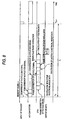
- Fig. 5 is a timing chart showing the operation of the position detector according to Embodiment 3 of the invention which calculates a position data on the basis of plural analog data of different cycles.
- a CPU corrects the phase of the COS signal of N cycles by the phase correcting process which has been described in Embodiment 1 of the invention and Embodiment 2 of the invention, and calculates a first electrical angle data ⁇ M (T n ) of N cycles, for example, an electrical angle data ⁇ M (T n ) of N cycles.
- the CPU corrects the phase of a COS signal of M cycles per revolution (hereinafter, referred to merely as M cycles, and M is an integer which is smaller than N), and calculates a first electrical angle data of M cycles, for example, an electrical angle data of M cycles.
- the electrical angle data of M cycles becomes an electrical angle data ⁇ M (T n + T ad2 ) at a time (T n + T ad2 ).
- Such electrical angle data with different times depending on cycles are corrected by an intercycle phase correcting process which will be described below, and thereafter the electrical angle data are combined to calculate a position data.
- Fig. 6 is a flowchart of the process of the intercycle phase correction between an electrical angle data of N cycles and an electrical angle data of M cycles.
- a movement velocity ⁇ n-1 at the last time between requests is calculated on the basis of a position data ⁇ (T n-2 ) which is produced at the request at a twice preceding time, a position data ⁇ (T n-1 ) which is produced at the request at a once preceding time, and the cycle T r of a request from the external apparatus (step S601).
- a moving distance ⁇ (T ad2 )in a time period T ad2 is predicted on the basis of the movement velocity ⁇ n-1 at the last time between requests and the time period T ad2 from the start of the A/D conversion of the SIN signal of N cycles to the start of the A/D conversion of the SIN signal of M cycles (step S602).
- a second electrical angle data of M cycles in the time period T ad2 for example, a changing amount of an electrical angle data of M cycles ⁇ M (T ad2 ) is calculated on the basis of a moving distance ⁇ (T ad2 ) in the time period T ad2 , a division number J of the position detector, a division number K of the electrical angle data of the signal of M cycles, and M.
- the division number J and the division number K are integers (step S603).
- a third electrical angle data of M cycles which is corrected, for example, an electrical angle data of M cycles ⁇ M (T n ) is calculated by subtracting the changing amount of an electrical angle data ⁇ M (T ad2 ) in the time period T ad2 from the electrical angle data of M cycles ⁇ M (T n + T ad2 ) before correction (step S604).
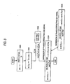
- Fig. 7 is a flowchart of a process of an intercycle phase correction in a position detector according to Embodiment 4 of the invention in which a position data is calculated from plural analog data of different cycles.
- Step S701 and step S702 are processes for predicting the moving distance ⁇ (T ad2 ) in the time period T ad2 in the same manner as step S401 and step S402 of Fig. 4. According to the processes shown in Fig. 7, even during a period when the position detection object is accelerated or decelerated, assumption of the moving distance at a higher accuracy can be performed, and the intercycle phase correction is performed at a higher accuracy. Therefore, correct synthesis of a position data can be performed.
- Fig. 8 is a flowchart of the operation of a position detector according to Embodiment 5 of the invention in which a position data is calculated from plural analog signals of different cycles.
- A/D conversion of an analog signal is started in synchronization with a request signal which is sent from an external apparatus.
- a CPU corrects the phase of the COS signal of N cycles by the phase correcting process which has been described in Embodiment 1 of the invention and Embodiment 2 of the invention, and calculates an electrical angle data ⁇ N (T n ) of N cycles. Similarly, also an electrical angle data of M cycles is calculated.
- the analog signals of each cycles are signals in which the phase is caused to lag by the influence of delay elements in the analog signal processing circuit. Therefore, obtained electrical angle data of each cycles lag with respect to true positions.
- phase lags due to the influence of the analog signal processing circuit are corrected by a process of electrical angle data phase correction, the intercycle phase correction which has been described in Embodiment 3 of the invention and Embodiment 4 of the invention is performed, and electrical angle data after correction are combined to calculate a position data.
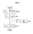
- Fig. 9 is a flowchart of the process of the phase correction of an electrical angle data of N cycles.
- a movement velocity ⁇ n-1 at the last time between requests is first calculated on the basis of a position data ⁇ ( Tn-2 ) which is produced at the request at a twice preceding time, a position data ⁇ (T n-1 ) which is produced at the request at a once preceding time, and the cycle T r of a request from the external apparatus (step S901).
- the frequency F N of the N-cycle signal is predicted on the basis of the movement velocity ⁇ n-1 ,the cycle T r of a request from the external apparatus, N, and J (step S902).
- ⁇ n-1 is the movement velocity at the last time, and its unit is pulse/sec. Since the division number J of the position detector is the number of pulses per revolution of the shaft, ( ⁇ n-1 /J) is the number of revolutions of the shaft in the last movement, i.e., the frequency of 1-cycle signal, and (N ⁇ n-1 /J) is the frequency of the N-cycle signal in the last movement.
- ⁇ N is a time constant of an analog circuit. Supposing the case where the time constant is varied in accordance with the frequency, a suffix N is attached.
- the amount of the phase lag ⁇ AN is added to the electrical angle data ⁇ N (T n ) which lags with respect to the above-mentioned true position, thereby calculating a corrected electrical angle data ⁇ N (T n )' (step S904).
- the process of correcting the phase of an electrical angle data enables even a position detecting apparatus which processes an analog signal of a higher frequency, to use a filter or the like in order to stabilize an analog signal processing circuit without impairing the accuracy. Furthermore, an effect is attained that it is not necessary to use electronic parts which are expensive, and fast in response speed.
- Fig. 10 is a flowchart of an electrical angle data phase correcting process for an electrical angle data of N cycles in a position detector according to Embodiment 6 of the invention in which a position data is calculated from plural analog signals of different cycles.
- Step S1001 is a process of predicting more correctly the movement velocity ⁇ n-1 at the present time.
- the position detecting apparatus of the invention is useful in the case where correct position detection must be performed at a low cost in various apparatuses such as a positioning control apparatus for a control object that is moved at a high speed.
Landscapes
- Physics & Mathematics (AREA)
- General Physics & Mathematics (AREA)
- Engineering & Computer Science (AREA)
- Signal Processing (AREA)
- Transmission And Conversion Of Sensor Element Output (AREA)
- Length Measuring Devices With Unspecified Measuring Means (AREA)
Claims (8)
- Positionserfassungsgerät, umfassend:Signalerzeugungsmittel (1, 2, 3) zum Erzeugen von Sinus- und Kosinussignalen als Reaktion auf das Bewegen eines Positionserfassungsobjekts,A/D-Wandelmittel (9) zum Umwandeln der Sinus- und Kosinussignale, die von den Signalerzeugungsmitteln erzeugt werden, in digitale Daten auf der Grundlage des Empfangs eines Anforderungssignals von einem externen Gerät,gekennzeichnet durchRechenmittel (10, 11, 12) zum Vorhersagen einer Menge einer Phasenverschiebung zwischen einer digitalen Information des Sinussignals und einer digitalen Information des Kosinussignals, wobei die Phasenverschiebung durch das Bewegen eines Positionserfassungsobjekts während der A/D-Umwandlung, die von dem A/D-Wandelmittel (9) ausgeführt wird, erzeugt wird, auf der Basis einer Bewegungsgeschwindigkeit, die aus einem Unterschied zwischen Positionsdaten in Anforderungsempfängen in einem Zeitpunkt Tn-2 und einem Zeitpunkt Tn-1 für das Korrigieren einer Phase entweder der digitalen Informationen des Sinussignals (S305) oder der digitalen Information des Kosinussignals (S304) berechnet wird, und zum Berechnen einer Positionsinformation in einem aktuellen Zeitpunkt Tn auf der Basis der digitalen Information der Phase, von welchen eine korrigiert ist, wobei Tn-1 eine Zeit ist, die TN vorausgeht, und Tn-2 eine Zeit ist, die Tn-1 vorausgeht.
- Positionserfassungsgerät nach Anspruch 1, wobei das Rechenmittel (10, 11, 12) die Menge der Phasenverschiebung für jedes Paar voraussagen kann, indem eine Beschleunigungsbewegung verwendet wird, die aus einem Unterschied zwischen der Bewegungsgeschwindigkeit in einem Zeitpunkt Tn-2 unmittelbar vor dem Zeitpunkt Tn-1 und der Bewegungsgeschwindigkeit in einem Zeitpunkt Tn-1 berechnet wird (S401), wobei die Bewegungsgeschwindigkeit in dem Zeitpunkt Tn-2 aus einem Unterschied zwischen Positionsdaten in Anforderungsempfängen in einem Zeitpunkt Tn-3 und dem Zeitpunkt Tn-2 berechnet wird, wobei Tn-3 eine Zeit ist, die Tn-2 vorausgeht.
- Positionserfassungsgerät nach Anspruch 1, wobei das Signalerzeugungsmittel (1, 2, 3) mehrere Signalpaare (4A, 4B, 4C), die aus einem Sinussignal und einem Kosinussignal bestehen, in unterschiedlichen Zyklen als Reaktion auf das Bewegen eines Positionserfassungsobjekts erzeugen kann,
wobei das A/D-Wandelmittel (9) sequenziell die Signale der Signalpaare in digitale Daten auf der Grundlage des Empfangs eines Anforderungssignals von einem externen Gerät umwandeln kann, und
wobei das Rechenmittel (10, 11, 12) einen Phasenunterschied zwischen den digitalen Daten der Signalpaare auf der Grundlage einer Bewegungsgeschwindigkeit, die aus einem Unterschied zwischen Positionsdaten in Anforderungsempfängen in einem Zeitpunkt Tn-2 und einem Zeitpunkt Tn-1 berechnet wird, korrigieren kann, wobei der Phasenunterschied während einer A/D-Umwandlungszeit eines Signals des Signalpaars erzeugt wird, zum Berechnen einer ersten elektrischen Winkelinformation auf der Grundlage der digitalen Daten des korrigierten Signalpaars, zum Berechnen einer zweiten elektrischen Winkelinformation auf der Grundlage der Bewegungsgeschwindigkeit, wobei die zweite elektrische Winkelinformation eine Bewegungsentfernung eines Positionserfassungsobjekts während einer Zeitspanne vom Empfang des Anforderungssignals zur A/D-Umwandlung des Signalpaars anzeigt, um ein Verfahren zum Erzielen einer dritten elektrischen Winkelinformation auf der Grundlage der ersten und zweiten elektrischen Winkelinformation auf jedem Signalpaar auszuführen, und zum Berechnen einer Positionsinformation in einem aktuellen Zeitpunkt Tn auf der Grundlage eines Ergebnisses des Prozesses. - Positionserfassungsgerät nach Anspruch 3, wobei das Rechenmittel (10, 11, 12) einen Gewichtungsprozess an jeder der berechneten dritten elektrischen Winkeldaten gemäß dem Zyklus ausführen und die Ergebnisse des Prozesses überlagern kann, um die Positionsdaten im aktuellen Zeitpunkt zu berechnen.
- Positionserfassungsgerät nach Anspruch 3, wobei das Rechenmittel (10, 11, 12) die Phasenverschiebungsmenge für jedes Paar voraussagen kann, indem Bewegungsbeschleunigung in dem Zeitpunkt Tn-1, die aus einem Unterschied zwischen der Bewegungsgeschwindigkeit in einem Zeitpunkt Tn-2 unmittelbar vor dem Zeitpunkt Tn-1, und der Bewegungsgeschwindigkeit in dem Zeitpunkt Tn-1 berechnet wird, verwendet wird, wobei die Bewegungsgeschwindigkeit im Zeitpunkt Tn-2 aus einem Unterschied zwischen Positionsdaten in Anforderungsempfängen in einem Zeitpunkt Tn-3 und dem Zeitpunkt Tn-2 berechnet wird.
- Positionserfassungsgerät nach Anspruch 4, wobei das Rechenmittel (10, 11, 12) die Phasenverschiebungsmenge für jedes Paar voraussagen kann, indem es Bewegungsbeschleunigung in dem Zeitpunkt Tn-1, die aus einem Unterschied zwischen der Bewegungsgeschwindigkeit in einem Zeitpunkt Tn-2 unmittelbar vor dem Zeitpunkt Tn-1 und der Bewegungsgeschwindigkeit in dem Zeitpunkt Tn-1 berechnet wird, verwendet, wobei der Unterschied zwischen der Bewegungsgeschwindigkeit in dem Zeitpunkt Tn-2 aus einem Unterschied zwischen Positionsdaten in Anforderungsempfängen in einem Zeitpunkt Tn-3 und dem Zeitpunkt Tn-2 berechnet wird.
- Positionserfassungsgerät nach einem der Ansprüche 1 bis 6, wobei das Rechenmittel (10, 11, 12) eine Phasenverzögerungsinformation eines Analogsignals, das durch eine Ursache einer Phasenverzögerung in einem Analogsignal-Verarbeitungsschaltkreis in einem Zeitpunkt T-1 erzeugt wird, auf der Grundlage der Bewegungsgeschwindigkeit in dem Zeitpunkt Tn-1, die aus dem Unterschied zwischen Positionsdaten in Anforderungsempfängen in dem Zeitpunkt Tn-2 und dem Zeitpunkt Tn-1 berechnet wird, voraussagen kann, und die Positionsdaten in dem aktuellen Zeitpunkt Tn durch weiteren Einsatz eines Ergebnisses der Voraussage berechnen kann.
- Positionserfassungsgerät nach einem der Ansprüche 1 bis 6, wobei das Rechenmittel (10, 11, 2) eine Phasenverzögerungsinformation eines Analogsignals, die durch eine Ursache einer Phasenverzögerung in einem Analogsignal-Verarbeitungsschaltkreis in dem Zeitpunkt Tn-1 erzeugt wird, auf der Grundlage der Bewegungsgeschwindigkeit in dem Zeitpunkt Tn-1, die aus dem Unterschied zwischen Positionsdaten in Anforderungsempfängen in dem Zeitpunkt Tn-2 und dem Zeitpunkt Tn-1 berechnet wird, und Bewegungsbeschleunigung in einem Zeitpunkt Tn-1, die aus einem Unterschied zwischen der Bewegungsgeschwindigkeit in einem Zeitpunkt Tn-2 unmittelbar vor dem Zeitpunkt Tn-1 und der Bewegungsgeschwindigkeit in dem Zeitpunkt Tn-1 voraussagen kann, wobei der Unterschied zwischen der Bewegungsgeschwindigkeit in dem Zeitpunkt Tn-2 unmittelbar vor dem Zeitpunkt Tn-1 aus einem Unterschied zwischen Positionsdaten in Anforderungsempfängen in einem Zeitpunkt Tn-3 und dem Zeitpunkt Tn-2 berechnet wird, und um die Positionsinformation in dem aktuellen Zeitpunkt Tn ferner durch Einsatz eines Ergebnisses der Vorhersage zu berechnen.
Applications Claiming Priority (3)
| Application Number | Priority Date | Filing Date | Title |
|---|---|---|---|
| JP31744298 | 1998-11-09 | ||
| JP31744298 | 1998-11-09 | ||
| PCT/JP1999/001088 WO2000028283A1 (en) | 1998-11-09 | 1999-03-05 | Position sensor |
Publications (3)
| Publication Number | Publication Date |
|---|---|
| EP1046884A1 EP1046884A1 (de) | 2000-10-25 |
| EP1046884A4 EP1046884A4 (de) | 2004-03-31 |
| EP1046884B1 true EP1046884B1 (de) | 2007-01-10 |
Family
ID=18088274
Family Applications (1)
| Application Number | Title | Priority Date | Filing Date |
|---|---|---|---|
| EP99971909A Expired - Lifetime EP1046884B1 (de) | 1998-11-09 | 1999-03-05 | Positionssensor |
Country Status (6)
| Country | Link |
|---|---|
| US (1) | US6232595B1 (de) |
| EP (1) | EP1046884B1 (de) |
| JP (1) | JP3610905B2 (de) |
| CN (1) | CN1184453C (de) |
| DE (1) | DE69934776T2 (de) |
| WO (1) | WO2000028283A1 (de) |
Families Citing this family (29)
| Publication number | Priority date | Publication date | Assignee | Title |
|---|---|---|---|---|
| US20040129869A1 (en) * | 2000-10-22 | 2004-07-08 | Lennart Stridsberg | Position transducer |
| DE10059433A1 (de) * | 2000-11-30 | 2002-06-06 | Hella Kg Hueck & Co | Verfahren zur Ermittlung der linearen Position oder der Winkelposition eines beweglichen Körpers |
| JP4088073B2 (ja) * | 2002-01-11 | 2008-05-21 | 株式会社ミツトヨ | 絶対位置測定装置 |
| JP3772121B2 (ja) | 2002-02-28 | 2006-05-10 | ファナック株式会社 | エンコーダの信号処理装置 |
| DE10243004A1 (de) * | 2002-09-17 | 2004-03-25 | Robert Bosch Gmbh | Verfahren zur Korrektur des Messfehlers eines Gebers |
| DE10392675B4 (de) * | 2003-04-11 | 2006-10-12 | Mitsubishi Denki K.K. | Drehcodierer |
| DE102004038621B3 (de) | 2004-08-09 | 2006-02-16 | Siemens Ag | Ermittlungsverfahren für ein Lagesignal |
| US20080052033A1 (en) * | 2004-08-12 | 2008-02-28 | University Of Virginia Patent Foundation | Method, Apparatus and Computer Program Product of Aliasing Discriminator for Encoder Interfaces |
| JP4953714B2 (ja) * | 2005-08-11 | 2012-06-13 | 株式会社ミツトヨ | エンコーダ出力の内挿方法及び内挿回路 |
| JP2007132909A (ja) * | 2005-11-14 | 2007-05-31 | Yaskawa Electric Corp | 信号処理装置 |
| JP4508103B2 (ja) * | 2005-12-26 | 2010-07-21 | 日本ビクター株式会社 | 位置検出方法 |
| KR100882400B1 (ko) * | 2006-06-19 | 2009-02-05 | 파나소닉 주식회사 | 인코더 신호의 위상 보정 회로 |
| KR20090007021A (ko) * | 2007-07-13 | 2009-01-16 | 삼성전자주식회사 | 엔코더 장치 및 이 장치의 캘리브레이션 방법 |
| DE102007062335B4 (de) * | 2007-12-21 | 2019-09-26 | Robert Bosch Gmbh | Verfahren und Vorrichtung zum Ermitteln von Messwerten aus einem zeitabhängigen Verlauf |
| JP5372624B2 (ja) * | 2009-02-18 | 2013-12-18 | 株式会社アイエイアイ | アブソリュート型リニアエンコーダとアクチュエータ |
| KR101612842B1 (ko) * | 2010-02-26 | 2016-04-15 | 한화테크윈 주식회사 | 엔코더 |
| KR101340931B1 (ko) * | 2010-04-12 | 2013-12-13 | 무라다기카이가부시끼가이샤 | 변위 센서 및 변위의 검출 방법 |
| JP5516145B2 (ja) * | 2010-06-30 | 2014-06-11 | セイコーエプソン株式会社 | 光学式検出装置、表示装置及び電子機器 |
| DE102011083042A1 (de) | 2010-11-29 | 2012-05-31 | Dr. Johannes Heidenhain Gmbh | Überwachungseinheit und Verfahren zur Überwachung von Positionssignalen inkrementaler Positionsmesseinrichtungen |
| CN102620755A (zh) * | 2011-10-14 | 2012-08-01 | 南京航空航天大学 | 基于tdc计时器的高精度位置信号检测方法和装置 |
| JP5932285B2 (ja) | 2011-10-14 | 2016-06-08 | キヤノン株式会社 | エンコーダおよびこれを備えた装置 |
| JP2013117430A (ja) * | 2011-12-02 | 2013-06-13 | Semiconductor Components Industries Llc | 位置検出回路および位置制御装置 |
| JP6422201B2 (ja) * | 2013-03-28 | 2018-11-14 | キヤノン株式会社 | 位置検出手段 |
| JP6136938B2 (ja) | 2014-01-06 | 2017-05-31 | ブラザー工業株式会社 | 現像カートリッジ |
| JP6472166B2 (ja) * | 2014-01-20 | 2019-02-20 | キヤノン株式会社 | 位置制御装置および方法 |
| JP6079687B2 (ja) | 2014-03-31 | 2017-02-15 | ブラザー工業株式会社 | カートリッジ |
| ES2656388T3 (es) * | 2015-07-27 | 2018-02-27 | Dr. Johannes Heidenhain Gmbh | Dispositivo de medición de posición y procedimiento para su funcionamiento |
| JP7028652B2 (ja) | 2018-01-16 | 2022-03-02 | 株式会社ミツトヨ | 測定装置 |
| JP7118809B2 (ja) * | 2018-08-27 | 2022-08-16 | キヤノン株式会社 | 位置検出装置およびこれを備えた装置、位置検出方法およびコンピュータプログラム |
Family Cites Families (9)
| Publication number | Priority date | Publication date | Assignee | Title |
|---|---|---|---|---|
| JPS5967458A (ja) * | 1982-10-12 | 1984-04-17 | Mitsubishi Electric Corp | デジタル速度検出方式 |
| IL87717A0 (en) | 1987-09-14 | 1989-02-28 | Exxon Chemical Patents Inc | Preparation of an active metallocene-alumoxane catalyst in situ during polymerization |
| JP2501227B2 (ja) | 1988-05-30 | 1996-05-29 | ファナック株式会社 | 絶対位置エンコ―ダ |
| JPH04359107A (ja) * | 1991-06-06 | 1992-12-11 | Nikon Corp | 計測装置 |
| JPH0526686A (ja) * | 1991-07-17 | 1993-02-02 | Yokogawa Electric Corp | 光学式エンコーダ |
| JPH0634872A (ja) * | 1992-07-14 | 1994-02-10 | Sony Corp | サンプリング系位置検出装置 |
| JPH07218288A (ja) * | 1994-01-28 | 1995-08-18 | Mitsubishi Electric Corp | 絶対位置検出装置及びその誤差補正方法 |
| JP3367260B2 (ja) * | 1995-03-24 | 2003-01-14 | 三菱電機株式会社 | エンコーダ装置及びサーボモーター制御装置 |
| DE19727352A1 (de) * | 1996-07-10 | 1998-01-15 | Heidenhain Gmbh Dr Johannes | Verfahren zur Positionsbestimmung und hierzu geeignetes Meßsystem |
-
1999
- 1999-03-05 WO PCT/JP1999/001088 patent/WO2000028283A1/ja not_active Ceased
- 1999-03-05 CN CN99802055.9A patent/CN1184453C/zh not_active Expired - Lifetime
- 1999-03-05 DE DE69934776T patent/DE69934776T2/de not_active Expired - Lifetime
- 1999-03-05 JP JP2000581419A patent/JP3610905B2/ja not_active Expired - Lifetime
- 1999-03-05 EP EP99971909A patent/EP1046884B1/de not_active Expired - Lifetime
-
2000
- 2000-07-10 US US09/613,312 patent/US6232595B1/en not_active Expired - Lifetime
Also Published As
| Publication number | Publication date |
|---|---|
| CN1288515A (zh) | 2001-03-21 |
| US6232595B1 (en) | 2001-05-15 |
| EP1046884A1 (de) | 2000-10-25 |
| EP1046884A4 (de) | 2004-03-31 |
| CN1184453C (zh) | 2005-01-12 |
| DE69934776T2 (de) | 2007-10-11 |
| DE69934776D1 (de) | 2007-02-22 |
| JP3610905B2 (ja) | 2005-01-19 |
| WO2000028283A1 (en) | 2000-05-18 |
Similar Documents
| Publication | Publication Date | Title |
|---|---|---|
| US6232595B1 (en) | Position detecting apparatus | |
| JPWO2000028283A1 (ja) | 位置検出装置 | |
| EP0978947B1 (de) | Resolversignalverarbeitungssystem | |
| US6188341B1 (en) | Encoder interpolation circuit which corrects an interpolation angle between a received sine-wave encoder signal and a cosine-wave encoder signal | |
| EP2789967B1 (de) | Mehrfach drehbare vorrichtung zur erkennung eines absoluten rotationswinkels und verfahren zur erkennung eines absoluten rotationswinkels | |
| US7088025B2 (en) | Variable-reluctance resolver and rotational angle sensor using same | |
| EP0331189B1 (de) | Weg-/Geschwindigkeits-Messverfahren und Vorrichtung | |
| JPS59133406A (ja) | 位置表示値を発生する方法と装置 | |
| JP3232795B2 (ja) | 検出装置 | |
| EP1054238B1 (de) | Verfahren und Gerät zur Messung der Position unter Verwendung von phasenverschobenen Signalen | |
| EP0199826B1 (de) | Verfahren zur bestimmung der ortung | |
| US20090295638A1 (en) | Use of a measurement signal evaluation means of a position measuring device to determine the time difference between a first event and a second event | |
| JP2002524754A (ja) | 粗位置インジケータを使用する精密位置エンコーダ | |
| JPH05322924A (ja) | 角加速度測定装置 | |
| EP0200791A1 (de) | Verfahren und vorrichtung zur bestimmung der ortung | |
| JP3365913B2 (ja) | 位置検出装置 | |
| JP4227352B2 (ja) | 一致検出装置及び方法 | |
| JP2007132909A (ja) | 信号処理装置 | |
| JPH0212014A (ja) | アブソリュート位置検出器及びその検出回路 | |
| JPH01248063A (ja) | エンコーダの速度信号検出回路 | |
| JPH0629723B2 (ja) | 絶対位置の測定方法およびその装置 | |
| JPH0215027B2 (de) | ||
| JP2002310610A (ja) | 位置検出方法および位置検出装置 | |
| JPH0617802B2 (ja) | エンコーダ内挿回路 | |
| JP2010139388A (ja) | 静電容量型位置検出器 |
Legal Events
| Date | Code | Title | Description |
|---|---|---|---|
| PUAI | Public reference made under article 153(3) epc to a published international application that has entered the european phase |
Free format text: ORIGINAL CODE: 0009012 |
|
| 17P | Request for examination filed |
Effective date: 20000705 |
|
| AK | Designated contracting states |
Kind code of ref document: A1 Designated state(s): DE FR |
|
| A4 | Supplementary search report drawn up and despatched |
Effective date: 20040213 |
|
| RIC1 | Information provided on ipc code assigned before grant |
Ipc: 7G 01D 5/244 B Ipc: 7G 01D 5/245 A |
|
| RAP1 | Party data changed (applicant data changed or rights of an application transferred) |
Owner name: MITSUBISHI DENKI KABUSHIKI KAISHA |
|
| GRAP | Despatch of communication of intention to grant a patent |
Free format text: ORIGINAL CODE: EPIDOSNIGR1 |
|
| GRAS | Grant fee paid |
Free format text: ORIGINAL CODE: EPIDOSNIGR3 |
|
| GRAA | (expected) grant |
Free format text: ORIGINAL CODE: 0009210 |
|
| AK | Designated contracting states |
Kind code of ref document: B1 Designated state(s): DE FR |
|
| REF | Corresponds to: |
Ref document number: 69934776 Country of ref document: DE Date of ref document: 20070222 Kind code of ref document: P |
|
| ET | Fr: translation filed | ||
| PLBE | No opposition filed within time limit |
Free format text: ORIGINAL CODE: 0009261 |
|
| STAA | Information on the status of an ep patent application or granted ep patent |
Free format text: STATUS: NO OPPOSITION FILED WITHIN TIME LIMIT |
|
| 26N | No opposition filed |
Effective date: 20071011 |
|
| REG | Reference to a national code |
Ref country code: FR Ref legal event code: PLFP Year of fee payment: 18 |
|
| REG | Reference to a national code |
Ref country code: FR Ref legal event code: PLFP Year of fee payment: 19 |
|
| REG | Reference to a national code |
Ref country code: FR Ref legal event code: PLFP Year of fee payment: 20 |
|
| PGFP | Annual fee paid to national office [announced via postgrant information from national office to epo] |
Ref country code: DE Payment date: 20180220 Year of fee payment: 20 |
|
| PGFP | Annual fee paid to national office [announced via postgrant information from national office to epo] |
Ref country code: FR Payment date: 20180223 Year of fee payment: 20 |
|
| REG | Reference to a national code |
Ref country code: DE Ref legal event code: R071 Ref document number: 69934776 Country of ref document: DE |