EP2789967B1 - Mehrfach drehbare vorrichtung zur erkennung eines absoluten rotationswinkels und verfahren zur erkennung eines absoluten rotationswinkels - Google Patents
Mehrfach drehbare vorrichtung zur erkennung eines absoluten rotationswinkels und verfahren zur erkennung eines absoluten rotationswinkels Download PDFInfo
- Publication number
- EP2789967B1 EP2789967B1 EP12848893.9A EP12848893A EP2789967B1 EP 2789967 B1 EP2789967 B1 EP 2789967B1 EP 12848893 A EP12848893 A EP 12848893A EP 2789967 B1 EP2789967 B1 EP 2789967B1
- Authority
- EP
- European Patent Office
- Prior art keywords
- shaft
- counter
- main shaft
- rotation
- angle detection
- Prior art date
- Legal status (The legal status is an assumption and is not a legal conclusion. Google has not performed a legal analysis and makes no representation as to the accuracy of the status listed.)
- Active
Links
Images


Classifications
-
- G—PHYSICS
- G01—MEASURING; TESTING
- G01D—MEASURING NOT SPECIALLY ADAPTED FOR A SPECIFIC VARIABLE; ARRANGEMENTS FOR MEASURING TWO OR MORE VARIABLES NOT COVERED IN A SINGLE OTHER SUBCLASS; TARIFF METERING APPARATUS; MEASURING OR TESTING NOT OTHERWISE PROVIDED FOR
- G01D5/00—Mechanical means for transferring the output of a sensing member; Means for converting the output of a sensing member to another variable where the form or nature of the sensing member does not constrain the means for converting; Transducers not specially adapted for a specific variable
- G01D5/12—Mechanical means for transferring the output of a sensing member; Means for converting the output of a sensing member to another variable where the form or nature of the sensing member does not constrain the means for converting; Transducers not specially adapted for a specific variable using electric or magnetic means
-
- G—PHYSICS
- G01—MEASURING; TESTING
- G01D—MEASURING NOT SPECIALLY ADAPTED FOR A SPECIFIC VARIABLE; ARRANGEMENTS FOR MEASURING TWO OR MORE VARIABLES NOT COVERED IN A SINGLE OTHER SUBCLASS; TARIFF METERING APPARATUS; MEASURING OR TESTING NOT OTHERWISE PROVIDED FOR
- G01D5/00—Mechanical means for transferring the output of a sensing member; Means for converting the output of a sensing member to another variable where the form or nature of the sensing member does not constrain the means for converting; Transducers not specially adapted for a specific variable
- G01D5/12—Mechanical means for transferring the output of a sensing member; Means for converting the output of a sensing member to another variable where the form or nature of the sensing member does not constrain the means for converting; Transducers not specially adapted for a specific variable using electric or magnetic means
- G01D5/244—Mechanical means for transferring the output of a sensing member; Means for converting the output of a sensing member to another variable where the form or nature of the sensing member does not constrain the means for converting; Transducers not specially adapted for a specific variable using electric or magnetic means influencing characteristics of pulses or pulse trains; generating pulses or pulse trains
- G01D5/245—Mechanical means for transferring the output of a sensing member; Means for converting the output of a sensing member to another variable where the form or nature of the sensing member does not constrain the means for converting; Transducers not specially adapted for a specific variable using electric or magnetic means influencing characteristics of pulses or pulse trains; generating pulses or pulse trains using a variable number of pulses in a train
- G01D5/2451—Incremental encoders
- G01D5/2452—Incremental encoders incorporating two or more tracks having an (n, n+1, ...) relationship
-
- G—PHYSICS
- G01—MEASURING; TESTING
- G01D—MEASURING NOT SPECIALLY ADAPTED FOR A SPECIFIC VARIABLE; ARRANGEMENTS FOR MEASURING TWO OR MORE VARIABLES NOT COVERED IN A SINGLE OTHER SUBCLASS; TARIFF METERING APPARATUS; MEASURING OR TESTING NOT OTHERWISE PROVIDED FOR
- G01D2205/00—Indexing scheme relating to details of means for transferring or converting the output of a sensing member
- G01D2205/20—Detecting rotary movement
- G01D2205/26—Details of encoders or position sensors specially adapted to detect rotation beyond a full turn of 360°, e.g. multi-rotation
-
- G—PHYSICS
- G01—MEASURING; TESTING
- G01D—MEASURING NOT SPECIALLY ADAPTED FOR A SPECIFIC VARIABLE; ARRANGEMENTS FOR MEASURING TWO OR MORE VARIABLES NOT COVERED IN A SINGLE OTHER SUBCLASS; TARIFF METERING APPARATUS; MEASURING OR TESTING NOT OTHERWISE PROVIDED FOR
- G01D2205/00—Indexing scheme relating to details of means for transferring or converting the output of a sensing member
- G01D2205/20—Detecting rotary movement
- G01D2205/28—The target being driven in rotation by additional gears
Definitions
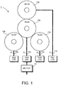
- the present invention provides a multi-turn rotation angle detection method, wherein: the multi-turn rotation angle detection apparatus further comprises a third counter-shaft in addition to the first counter-shaft and the second counter-shaft; there is a teeth number difference of 1 between the main shaft gear and the third counter-shaft; the multi-turn rotation angle detection method further comprises a step of generating a third counter-shaft periodic signal which represents a difference in rotation count between the main shaft and the third counter-shaft from the 1-fold angle detection value P 0(1X) of the main shaft and a 1-fold angle detection value P 3(1X) of the second counter-shaft detected by the third counter-shaft angle detector; and the step of determining the rotation count of the main shaft further includes a step of determining the rotation count of the main shaft from the first counter-shaft periodic signal, the second counter-shaft periodic signal, and the third counter-shaft periodic signal.
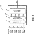
- the detection values P 0(4X) , P 1(1X) , P 2(1X) , and P 3(1X) are sent to a multi-turn computation circuit 25.
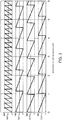
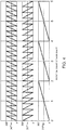
- Fig. 3 shows changes of the detection values P 0(4X) , P 1(1X) , P 2(1X) , and P 3(1X) in relation to rotation count of the main shaft 10a.
- the abscissa represents the rotation count of the main shaft 10a and the ordinate represents an electrical angle of the shaft corresponding to a value detected as each detection value, where the values on the ordinate are expressed in degrees ranging from 0° to 360° for ease of understanding, but may be expressed in values from 0 to 1.
Landscapes
- Physics & Mathematics (AREA)
- General Physics & Mathematics (AREA)
- Transmission And Conversion Of Sensor Element Output (AREA)
- Measurement Of Length, Angles, Or The Like Using Electric Or Magnetic Means (AREA)
Claims (10)
- Vorrichtung zur Detektion eines Rotationswinkels über mehrere Drehungen, die Folgendes umfasst: ein Hauptwellenrad (10b), das auf einer Hauptwelle (10a) montiert ist; ein erstes Gegenwellenrad (11b) und ein zweites Gegenwellenrad (12b), die angepasst sind, in die Hauptwelle einzugreifen; eine erste Gegenwelle (11a) und eine zweite Gegenwelle (12a), die angepasst sind, Rotationen des ersten bzw. zweiten Gegenwellenrades zu übertragen;
einen Satz Winkeldetektoren, einschließlich eines Hauptwellenwinkeldetektors (RS0), der angepasst ist, einen Rotationswinkel der Hauptwelle zu detektieren, und eines ersten und zweiten Gegenwellenwinkeldetektors (RS1, RS2), die angepasst sind, Rotationswinkel der ersten und zweiten Gegenwelle zu detektieren, wobei der Hauptwellenwinkeldetektor N Zyklen eines N-fachen Winkeldetektionswertes P0(NX) pro Rotation der Hauptwelle ausgibt und der erste und zweite Gegenwellenwinkeldetektor einen Zyklus von 1-fachen Winkeldetektionswerten P1(1X) bzw. P2(1X) pro Rotation der jeweiligen Gegenwellen ausgeben; und
einen Radmechanismus mit einer Zahnanzahldifferenz von zwei oder einer größeren Ganzzahl a zwischen dem ersten Gegenwellenrad und dem Hauptwellenrad und einer Zahnanzahldifferenz von 1 zwischen dem Hauptwellenrad und dem zweiten Gegenwellenrad, wobei die Anzahl von Zähnen des ersten Gegenwellenrades ein integrales Vielfaches eines Produkts aus der Zahnanzahldifferenz a und einem Wellenwinkelmultiplikator N des an der Hauptwelle befestigten Winkeldetektors ist,
wobei ein absoluter Rotationswinkel der Hauptwelle über mehrere Drehungen anhand der Rotationswinkeldetektionswerte der Hauptwelle, der ersten Gegenwelle und der zweiten Gegenwelle bestimmt wird,
wobei die Vorrichtung zur Detektion eines Rotationswinkels über mehrere Drehungen ferner Hauptwellenrotationswinkeldetektionsmittel umfasst, die angepasst sind, ein Signal P0((aN/M)xX), von dem ein Zyklus M/aN Rotationen der Hauptwelle entspricht, anhand des N-fachen Winkeldetektionswerts P0(NX), der vom Hauptwellenwinkeldetektor detektiert wird, und des 1-fachen Winkeldetektionswerts P1(1X) der ersten Gegenwelle, der vom ersten Gegenwellenwinkeldetektor detektiert wird, zu bestimmen, wobei M die Anzahl von Zähnen der ersten Gegenwelle ist, einen Unterscheidungswert vom Signal P0((aN/MxX) zu erhalten, der anzeigt, zu welchem Zyklus der N Zyklen der N-fache Winkeldetektionswert P0(NX), der vom Hauptwellenwinkeldetektor detektiert wird, gehört, und einen Zyklus eines 1-fachen Winkeldetektionswerts P0(1X) der Hauptwelle pro Rotation der Hauptwelle anhand des Unterscheidungswerts und des N-fachen Winkeldetektionswerts P0(NX) zu synthetisieren, und
Mittel zum Detektieren einer Wellenrotationszahl, die angepasst sind, ein erstes periodisches Gegenwellensignal, das eine Differenz der Rotationszahl zwischen der Hauptwelle und der ersten Gegenwelle repräsentiert, aus dem 1-fachen Winkeldetektionswert P0(1X) der Hauptwelle und dem 1-fachen Winkeldetektionswert P1(1X) der ersten Gegenwelle zu erzeugen, ein zweites periodisches Gegenwellensignal, das eine Differenz der Rotationszahl zwischen der Hauptwelle und der zweiten Gegenwelle repräsentiert, aus dem 1-fachen Winkeldetektionswert P0(1X) der Hauptwelle und dem 1-fachen Winkeldetektionswert P2(1X) der zweiten Gegenwelle, der vom zweiten Gegenwellenwinkeldetektor detektiert wird, zu erzeugen und die Rotationszahl der Hauptwelle anhand des ersten periodischen Gegenwellensignals und des zweiten periodischen Gegenwellensignals zu bestimmen. - Vorrichtung zur Detektion eines Rotationswinkels über mehrere Drehungen nach Anspruch 1, wobei:der Radmechanismus ferner ein drittes Gegenwellenrad (13b) beinhaltet, das angepasst ist, in das Hauptwellenrad einzugreifen, und eine dritte Gegenwelle (13a), die angepasst ist, Rotation auf das dritte Gegenwellenrad zu übertragen;ein Winkeldetektor (RS3) einen Zyklus eines 1-fachen Winkeldetektionswerts P3(1X) der dritten Gegenwelle pro Rotation der dritten Gegenwelle ausgibt; unddie Mittel zum Detektieren einer Wellenrotationszahl ferner ein drittes periodisches Gegenwellensignal, das eine Differenz der Rotationszahl zwischen der Hauptwelle und der dritten Gegenwelle repräsentiert, aus dem 1-fachen Winkeldetektionswert P0(1X) der Hauptwelle und dem 1-fachen Winkeldetektionswert P3(1X) der dritten Gegenwelle erzeugen und die Rotationszahl der Hauptwelle anhand des ersten periodischen Gegenwellensignals, des zweiten periodischen Gegenwellensignals und des dritten periodischen Gegenwellensignals bestimmen.
- Vorrichtung zur Detektion eines Rotationswinkels über mehrere Drehungen nach Anspruch 1, die zusätzlich zur ersten Gegenwelle (11a) und zur zweiten Gegenwelle (12a) eine dritte Gegenwelle (13a) umfasst, wobei: zwischen dem Hauptwellenrad und der dritten Gegenwelle eine Zahnanzahldifferenz von 1 besteht; ein drittes periodisches Gegenwellensignal, das eine Differenz der Rotationszahl zwischen der Hauptwelle und der dritten Gegenwelle repräsentiert, aus dem 1-fachen Winkeldetektionswert P0(1X) der Hauptwelle und einem 1-fachen Winkeldetektionswert P3(1X) der zweiten Gegenwelle, der vom dritten Gegenwellenwinkeldetektor detektiert wird, erzeugt wird und die Mittel zum Detektieren einer Wellenrotationszahl die Rotationszahl der Hauptwelle anhand des ersten periodischen Gegenwellensignals, des zweiten periodischen Gegenwellensignals und des dritten periodischen Gegenwellensignals bestimmt.
- Vorrichtung zur Detektion eines Rotationswinkels über mehrere Drehungen nach Anspruch 2, wobei, wenn S die Anzahl von Zähnen des dritten Gegenwellenrads (13b) bezeichnet, wenn die Anzahl von Zähnen des zweiten Gegenwellenrads (12b) Q = R - 1 ist, die Anzahl von Zähnen des dritten Gegenwellenrads S = R + 1 ist, und wenn die Anzahl von Zähnen des zweiten Gegenwellenrads Q = R + 1 ist, die Anzahl von Zähnen des dritten Gegenwellenrads S = R - 1 ist.
- Vorrichtung zur Detektion eines Rotationswinkels über mehrere Drehungen nach Anspruch 1, wobei der Unterscheidungswert P0((aN/M)xX) ein Rest ist, der durch Dividieren einer Summe oder Differenz zwischen dem N-fachen Winkeldetektionswert P0(NX) der Hauptwelle und einem N-fachen Winkeldetektionswert P1(NX) der ersten Gegenwelle durch eine Standardeinheitsmenge u pro Zyklus erhalten wird, wobei der N-fache Winkeldetektionswert P1(NX) als ein Rest berechnet wird, der durch Multiplizieren des 1-fachen Winkeldetektionswerts P1(1X) der ersten Gegenwelle mit N und Dividieren eines resultierenden Produkts mit der Standardeinheitsmenge u erhalten wird, wobei der 1-fache Winkeldetektionswert P1(1X) vom ersten Gegenwellenwinkeldetektor detektiert wird.
- Verfahren zur Detektion eines Rotationswinkels über mehrere Drehungen für eine Vorrichtung zur Detektion eines Rotationswinkels über mehrere Drehungen, die ein Hauptwellenrad (10b), das auf einer Hauptwelle (10a) montiert ist, die Rotation einer Rotationsantriebsquelle überträgt, ein erstes Gegenwellenrad (11b) und ein zweites Gegenwellenrad (12b), die angepasst sind, in die Hauptwelle einzugreifen, eine erste Gegenwelle (11a) und eine zweite Gegenwelle (12a), die angepasst sind, Rotationen des ersten bzw. zweiten Gegenwellenrades zu übertragen, umfasst,
einen Satz Winkeldetektoren, einschließlich eines Hauptwellenwinkeldetektors (RS0), der angepasst ist, einen Rotationswinkel der Hauptwelle zu detektieren, und eines ersten und zweiten Gegenwellenwinkeldetektors (RS1, RS2), die angepasst sind, Rotationswinkel der ersten und zweiten Gegenwelle zu detektieren, wobei der Hauptwellenwinkeldetektor N Zyklen eines N-fachen Winkeldetektionswertes P0(NX) pro Rotation der Hauptwelle ausgibt und der erste und zweite Gegenwellenwinkeldetektor einen Zyklus von 1-fachen Winkeldetektionswerten P1(1X) bzw. P2(1X) pro Rotation der jeweiligen Gegenwellen ausgeben, und
einen Radmechanismus mit einer Zahnanzahldifferenz von zwei oder einer größeren Ganzzahl a zwischen dem ersten Gegenwellenrad und dem Hauptwellenrad und einer Zahnanzahldifferenz von 1 zwischen dem zweiten Gegenwellenrad und dem Hauptwellenrad, wobei die Anzahl von Zähnen des ersten Gegenwellenrades ein integrales Vielfaches eines Produkts aus der Zahnanzahldifferenz a und einem Wellenwinkelmultiplikator N des an der Hauptwelle befestigten Winkeldetektors ist,
wobei ein absoluter Rotationswinkel der Hauptwelle über mehrere Drehungen anhand der Rotationswinkeldetektionswerte der Hauptwelle, der ersten Gegenwelle und der zweiten Gegenwelle bestimmt wird,
das Verfahren zur Detektion eines Rotationswinkels über mehrere Drehungen, das einen Schritt des Detektierens von N Zyklen eines N-fachen Winkeldetektionswertes P0(NX) pro Rotation der Hauptwelle, der der Rotationswinkel der Hauptwelle ist, und des Detektierens eines Zyklus von 1-fachen Winkeldetektionswerten P1(1X) bzw. P2(1X) pro Rotation der jeweiligen Gegenwellen, die die Rotationswinkel der ersten bzw. zweiten Gegenwelle sind, umfasst;
einen Schritt des Bestimmens eines Signals P0((aN/M)xX), von dem ein Zyklus M/aN Rotationen der Hauptwelle entspricht, anhand des N-fachen Winkeldetektionswerts P0(NX), der vom Hauptwellenwinkeldetektor detektiert wird, und des 1-fachen Winkeldetektionswerts P1(1X) der ersten Gegenwelle, der vom ersten Gegenwellenwinkeldetektor detektiert wird, wobei M die Anzahl von Zähnen der ersten Gegenwelle ist, des Erhaltens eines Unterscheidungswerts vom Signal P0((aN/MxX), der identifiziert, zu welchem Zyklus der N Zyklen der N-fache Winkeldetektionswert P0(NX), der vom Hauptwellenwinkeldetektor detektiert wird, gehört, und dadurch des Bestimmens eines Rotationswinkels innerhalb einer Rotation der Hauptwelle und
einen Schritt des Synthetisierens eines Zyklus eines 1-fachen Winkeldetektionswerts P0(1X) der Hauptwelle pro Rotation der Hauptwelle anhand des Unterscheidungswerts und des N-fachen Winkeldetektionswerts P0(NX), des Erzeugens eines ersten periodischen Gegenwellensignals, das eine Differenz der Rotationszahl zwischen der Hauptwelle und der ersten Gegenwelle repräsentiert, aus dem 1-fachen Winkeldetektionswert P0(1X) der Hauptwelle und dem 1-fachen Winkeldetektionswert P1(1X) der ersten Gegenwelle, des Erzeugens eines zweiten periodischen Gegenwellensignals, das eine Differenz der Rotationszahl zwischen der Hauptwelle und der zweiten Gegenwelle repräsentiert, aus dem 1-fachen Winkeldetektionswert P0(1X) der Hauptwelle und dem 1-fachen Winkeldetektionswert P2(1X) der zweiten Gegenwelle, der vom zweiten Gegenwellenwinkeldetektor detektiert wird, und des Bestimmens der Rotationszahl der Hauptwelle anhand des ersten periodischen Gegenwellensignals und des zweiten periodischen Gegenwellensignals. - Verfahren zur Detektion eines Rotationswinkels über mehrere Drehungen nach Anspruch 6, wobei:der Radmechanismus ferner ein drittes Gegenwellenrad (13b) beinhaltet, das angepasst ist, in das Hauptwellenrad einzugreifen, und eine dritte Gegenwelle (13a), die angepasst ist, Rotation auf das dritte Gegenwellenrad zu übertragen;ein Winkeldetektor (RS3) einen Zyklus eines 1-fachen Winkeldetektionswerts P3(1X) der dritten Gegenwelle pro Rotation der dritten Gegenwelle ausgibt; unddie Mittel zum Detektieren einer Wellenrotationszahl ferner ein drittes periodisches Gegenwellensignal, das eine Differenz der Rotationszahl zwischen der Hauptwelle und der dritten Gegenwelle repräsentiert, aus dem 1-fachen Winkeldetektionswert P0(1X) der Hauptwelle und dem 1-fachen Winkeldetektionswert P3(1X) der dritten Gegenwelle erzeugen und die Rotationszahl der Hauptwelle anhand des ersten periodischen Gegenwellensignals, des zweiten periodischen Gegenwellensignals und des dritten periodischen Gegenwellensignals bestimmen.
- Verfahren zur Detektion eines Rotationswinkels über mehrere Drehungen nach Anspruch 6, wobei:die Vorrichtung zur Detektion eines Rotationswinkels über mehrere Drehungen ferner zusätzlich zur ersten Gegenwelle (11a) und zur zweiten Gegenwelle (12a) eine dritte Gegenwelle (13a) umfasst, zwischen dem Hauptwellenrad (10b) und dem dritten Gegenwellenrad (13b) eine Zahnanzahldifferenz von 1 besteht; das Verfahren zur Detektion eines Rotationswinkels über mehrere Drehungen ferner einen Schritt des Erzeugens eines dritten periodischen Gegenwellensignals, das eine Differenz der Rotationszahl zwischen der Hauptwelle und der dritten Gegenwelle repräsentiert, aus dem 1-fachen Winkeldetektionswert P0(1X) der Hauptwelle und einem 1-fachen Winkeldetektionswert P3(1X) der zweiten Gegenwelle, der vom dritten Gegenwellenwinkeldetektor detektiert wird, umfasst und der Schritt des Bestimmens der Rotationszahl der Hauptwelle ferner einen Schritt des Bestimmens der Rotationszahl der Hauptwelle anhand des ersten periodischen Gegenwellensignals, des zweiten periodischen Gegenwellensignals und des dritten periodischen Gegenwellensignals umfasst.
- Verfahren zur Detektion eines Rotationswinkels über mehrere Drehungen nach Anspruch 7, wobei, wenn S die Anzahl von Zähnen des dritten Gegenwellenrads (13b) bezeichnet, wenn die Anzahl von Zähnen des zweiten Gegenwellenrads (12b) Q = R - 1 ist, die Anzahl von Zähnen des dritten Gegenwellenrads (13b) S = R + 1 ist, und wenn die Anzahl von Zähnen des zweiten Gegenwellenrads (12b) Q = R + 1 ist, die Anzahl von Zähnen des dritten Gegenwellenrads (13b) S = R - 1 ist.
- Verfahren zur Detektion eines Rotationswinkels über mehrere Drehungen nach Anspruch 6, wobei der Unterscheidungswert P0((aN/M)xX) ein Rest ist, der durch Dividieren einer Summe oder Differenz zwischen dem N-fachen Winkeldetektionswert P0(NX) der Hauptwelle und einem N-fachen Winkeldetektionswert P1(NX) der ersten Gegenwelle durch eine Standardeinheitsmenge u pro Zyklus erhalten wird, wobei der N-fache Winkeldetektionswert P1(NX) als ein Rest berechnet wird, der durch Multiplizieren des 1-fachen Winkeldetektionswerts P1(1X) der ersten Gegenwelle mit N und Dividieren eines resultierenden Produkts mit der Standardeinheitsmenge u erhalten wird, wobei der 1-fache Winkeldetektionswert P1(1X) vom ersten Gegenwellenwinkeldetektor detektiert wird.
Applications Claiming Priority (2)
| Application Number | Priority Date | Filing Date | Title |
|---|---|---|---|
| JP2011248663A JP5420624B2 (ja) | 2011-11-14 | 2011-11-14 | 多回転アブソリュート回転角検出装置及びアブソリュート回転角を検出する方法 |
| PCT/JP2012/076093 WO2013073319A1 (ja) | 2011-11-14 | 2012-10-09 | 多回転アブソリュート回転角検出装置及びアブソリュート回転角を検出する方法 |
Publications (3)
| Publication Number | Publication Date |
|---|---|
| EP2789967A1 EP2789967A1 (de) | 2014-10-15 |
| EP2789967A4 EP2789967A4 (de) | 2015-10-28 |
| EP2789967B1 true EP2789967B1 (de) | 2017-05-31 |
Family
ID=48429389
Family Applications (1)
| Application Number | Title | Priority Date | Filing Date |
|---|---|---|---|
| EP12848893.9A Active EP2789967B1 (de) | 2011-11-14 | 2012-10-09 | Mehrfach drehbare vorrichtung zur erkennung eines absoluten rotationswinkels und verfahren zur erkennung eines absoluten rotationswinkels |
Country Status (7)
| Country | Link |
|---|---|
| US (1) | US9528855B2 (de) |
| EP (1) | EP2789967B1 (de) |
| JP (1) | JP5420624B2 (de) |
| KR (1) | KR101942130B1 (de) |
| CN (1) | CN103930748B (de) |
| ES (1) | ES2638332T3 (de) |
| WO (1) | WO2013073319A1 (de) |
Families Citing this family (14)
| Publication number | Priority date | Publication date | Assignee | Title |
|---|---|---|---|---|
| TWI500907B (zh) | 2011-01-07 | 2015-09-21 | Oriental Motor Co Ltd | 多圈旋轉絕對旋轉角之檢測裝置及該旋轉角之檢測方法 |
| JP5545769B2 (ja) | 2011-07-12 | 2014-07-09 | オリエンタルモーター株式会社 | アブソリュート変位量を算出する装置及びその方法 |
| JP6224349B2 (ja) * | 2013-05-15 | 2017-11-01 | 株式会社アイエイアイ | ステッピングモータ制御システム及びステッピングモータ制御方法 |
| SE538475C2 (en) * | 2014-03-28 | 2016-07-19 | Allied Motion Stockholm Ab | Method for deriving an absolute multiturn rotational angle of a rotating shaft, and a device therefore |
| GB2527819A (en) * | 2014-07-03 | 2016-01-06 | Moog Controls Ltd | Rotation transducer |
| JP7076683B2 (ja) * | 2016-06-27 | 2022-05-30 | Smc株式会社 | 位置検出装置 |
| DE102017108863A1 (de) * | 2017-04-26 | 2018-10-31 | Valeo Schalter Und Sensoren Gmbh | Ermitteln eines Drehwinkels einer Lenkwelle mittels dreier Zahnräder |
| JP6626476B2 (ja) * | 2017-07-13 | 2019-12-25 | オリエンタルモーター株式会社 | 歯車を適正位置に保持する歯車支持機構を用いる回転角検出装置 |
| KR101881559B1 (ko) * | 2017-07-19 | 2018-08-24 | 성균관대학교산학협력단 | 다회전 검출 장치 및 방법 |
| EP3459844B1 (de) * | 2017-09-25 | 2022-07-13 | Ratier-Figeac SAS | Vorrichtung zur erfassung einer aktuatorposition |
| US10670386B2 (en) * | 2018-04-19 | 2020-06-02 | Infineon Technologies Ag | Multi-turn counter sensor failure detection |
| JP7234577B2 (ja) | 2018-10-31 | 2023-03-08 | セイコーエプソン株式会社 | ロボットシステム、ロボット制御方法、及びエンコーダー |
| JP7234580B2 (ja) * | 2018-10-31 | 2023-03-08 | セイコーエプソン株式会社 | ロボットシステム、ロボット制御方法、及びエンコーダー |
| DE102022001510A1 (de) * | 2022-04-29 | 2023-11-02 | Methode Electronics Malta Ltd. | Drehpositionssensor |
Family Cites Families (62)
| Publication number | Priority date | Publication date | Assignee | Title |
|---|---|---|---|---|
| US4339950A (en) * | 1980-02-19 | 1982-07-20 | Lendino Nicholas C | Counting mechanism attachment for a fuel tank |
| JPS58106691A (ja) | 1981-12-21 | 1983-06-25 | 株式会社エスジ− | アブソリュート位置検出装置 |
| JPS59190612A (ja) | 1983-04-13 | 1984-10-29 | Fanuc Ltd | 絶対位置検出方法 |
| JPS603099A (ja) * | 1983-06-20 | 1985-01-09 | 株式会社エスジ− | アブソリユ−ト位置検出装置 |
| JPH0678907B2 (ja) * | 1984-05-15 | 1994-10-05 | 東芝機械株式会社 | アブソリュート位置の検知装置 |
| JPS60239618A (ja) | 1984-05-15 | 1985-11-28 | Toshiba Mach Co Ltd | 回転体の回転量をアブソリユ−ト値で検知する方法およびその装置 |
| JPS614918A (ja) * | 1984-06-20 | 1986-01-10 | Toyota Motor Corp | レゾルバを用いた多回転の回転位置検出用アブソリユ−トセンサ |
| JPS6117913A (ja) | 1984-07-04 | 1986-01-25 | Omron Tateisi Electronics Co | ロ−タリエンコ−ダ |
| EP0201106A3 (de) * | 1985-05-10 | 1990-01-17 | Hewlett-Packard Company | Absoluter Lagekodierer |
| JPS63118614A (ja) * | 1986-11-07 | 1988-05-23 | Toyota Motor Corp | 多回転アブソリユ−トエンコ−ダの多回転検出装置 |
| FR2609136B1 (fr) * | 1986-12-31 | 1989-12-01 | Camara Alpha | Egalisateur de couple pour arbres contrarotatifs |
| JPS63242028A (ja) | 1987-03-30 | 1988-10-07 | Ishikawajima Harima Heavy Ind Co Ltd | 多回転絶対番地型位置検出器 |
| JPH0353114A (ja) * | 1989-07-21 | 1991-03-07 | Sony Magnescale Inc | 位置検出装置 |
| JPH0330648U (de) * | 1989-08-04 | 1991-03-26 | ||
| JPH0371009A (ja) * | 1989-08-10 | 1991-03-26 | Mitsubishi Kasei Corp | 位置信号補正装置 |
| JPH0421813A (ja) | 1990-05-16 | 1992-01-24 | Matsushita Electric Ind Co Ltd | 光ビーム走査装置 |
| JPH0421813U (de) * | 1990-06-11 | 1992-02-24 | ||
| JPH04130218A (ja) * | 1990-09-20 | 1992-05-01 | Sony Magnescale Inc | 位置検出装置 |
| JPH0635932B2 (ja) | 1991-02-12 | 1994-05-11 | 株式会社エスジー | アブソリュート回転位置検出装置 |
| JPH0538243A (ja) | 1991-08-06 | 1993-02-19 | Shimano Inc | 釣り竿の糸ガイド製造方法 |
| JPH05141911A (ja) * | 1991-11-16 | 1993-06-08 | Yamaha Corp | ロータリエンコーダ |
| JPH0672187A (ja) | 1992-05-28 | 1994-03-15 | Mitsubishi Electric Corp | 自動変速機付車両用エンジン制御装置及びその制御方法 |
| US5457371A (en) * | 1993-08-17 | 1995-10-10 | Hewlett Packard Company | Binary locally-initializing incremental encoder |
| DE19506938A1 (de) * | 1995-02-28 | 1996-08-29 | Bosch Gmbh Robert | Verfahren und Vorrichtung zur Winkelmessung bei einem drehbaren Körper |
| US6026925A (en) | 1995-12-19 | 2000-02-22 | Denso Corporation | Electrically driven power assisting device |
| US5950052A (en) | 1996-09-17 | 1999-09-07 | Seiko Epson Corporation | Image forming apparatus |
| DE19855960A1 (de) * | 1998-12-04 | 2000-06-08 | Bosch Gmbh Robert | Vorrichtung und Verfahren zur Messung der Winkellage eines drehbaren Körpers |
| JP2001004405A (ja) | 1999-06-22 | 2001-01-12 | Sankyo Seiki Mfg Co Ltd | 磁気式エンコーダ装置 |
| JP3665732B2 (ja) * | 2000-09-29 | 2005-06-29 | 山洋電気株式会社 | 絶対位置検出方法 |
| JP3704462B2 (ja) * | 2000-09-29 | 2005-10-12 | 山洋電気株式会社 | リラクタンスレゾルバを用いた絶対位置検出器 |
| DE10048911C1 (de) * | 2000-10-02 | 2002-04-25 | Ruf Electronics Gmbh | Verfahren und Vorrichtung zur Bestimmung der Absolutposition bei Weg- und Winkelgebern |
| JP2002116057A (ja) * | 2000-10-06 | 2002-04-19 | Yaskawa Electric Corp | 多回転式絶対値エンコーダ装置 |
| KR100913631B1 (ko) * | 2001-10-19 | 2009-08-24 | 가부시키가이샤 야스카와덴키 | 다회전식 인코더 |
| US7307415B2 (en) | 2002-02-14 | 2007-12-11 | Bvr Technologies Co. | Contactless angular position sensor and method for sensing angular position of a rotatable shaft |
| JP3967963B2 (ja) | 2002-05-29 | 2007-08-29 | オークマ株式会社 | アブソリュート変位検出装置 |
| DE60306998T2 (de) | 2002-07-10 | 2006-11-23 | Jtekt Corp. | Drehmomentsensor |
| JP2004138606A (ja) | 2002-09-24 | 2004-05-13 | Yazaki Corp | 舵角センサ |
| JP4241012B2 (ja) * | 2002-11-25 | 2009-03-18 | パナソニック株式会社 | 回転角度検出装置 |
| DE10332413B3 (de) * | 2003-07-16 | 2005-04-28 | Ic Haus Gmbh | Positionsmessvorrichtung zum Ermitteln von Winkel- oder Längenpositionen |
| KR100610380B1 (ko) * | 2003-11-11 | 2006-08-09 | 현대모비스 주식회사 | 차량용 조향축의 절대조향각 측정방법 |
| JP2006017663A (ja) * | 2004-07-05 | 2006-01-19 | Alps Electric Co Ltd | 回転角検出装置 |
| ES2305959T3 (es) | 2004-08-28 | 2008-11-01 | Luk Lamellen Und Kupplungsbau Beteiligungs Kg | Procedimiento para determinar la posicion angular de giro del arbol de levas de un motor de combustion de pistones alternativos con relacion al cigueñal. |
| JP2007078459A (ja) * | 2005-09-13 | 2007-03-29 | Yaskawa Electric Corp | 多回転式絶対値エンコーダおよび回転機械 |
| DE102006006359A1 (de) * | 2006-02-11 | 2007-08-16 | Leopold Kostal Gmbh & Co. Kg | Drehwinkelsensor sowie Verfahren zum Bestimmen der absoluten Winkelstellung eines über mehrere Runden drehbaren Körpers |
| WO2007119701A1 (ja) | 2006-04-10 | 2007-10-25 | Panasonic Corporation | 回転角度検出装置 |
| JP2008039737A (ja) | 2006-08-10 | 2008-02-21 | Yaskawa Electric Corp | 多回転量算出方法、バッテリーレス多回転式絶対値エンコーダ装置およびこれを用いた減速機付アクチュエータ |
| US20100114524A1 (en) * | 2006-11-10 | 2010-05-06 | The Furukawa Electric Co., Ltd | Rotation angle detection apparatus |
| JP4197036B2 (ja) | 2007-02-07 | 2008-12-17 | トヨタ自動車株式会社 | 動力伝達装置の制御装置 |
| JP4992516B2 (ja) * | 2007-04-02 | 2012-08-08 | パナソニック株式会社 | 回転角度検出装置 |
| JP4443585B2 (ja) * | 2007-04-17 | 2010-03-31 | 三菱電機株式会社 | 伝達比可変機構用センサシステム及びこれを用いた操舵装置 |
| DE102008011448A1 (de) * | 2008-02-27 | 2009-09-03 | Valeo Schalter Und Sensoren Gmbh | Anordnung zur Erfassung eines Drehwinkels |
| JP5167456B2 (ja) * | 2008-03-17 | 2013-03-21 | 多摩川精機株式会社 | アブソリュートセンサの多回転検出方法 |
| JP4617368B2 (ja) | 2008-03-25 | 2011-01-26 | 山洋電気株式会社 | バッテリレス絶対位置検出用エンコーダ |
| JP4572951B2 (ja) | 2008-04-11 | 2010-11-04 | 富士ゼロックス株式会社 | 記録材移動装置及び画像形成装置 |
| US7579829B1 (en) | 2008-07-06 | 2009-08-25 | Avago Technologies Ecbu Ip (Singapore) Pte. Ltd. | Inductive multi-turn encoder |
| US20100235054A1 (en) * | 2009-03-11 | 2010-09-16 | Kostal Of America | Steering angle sensor |
| CN102648388B (zh) | 2009-10-19 | 2015-04-15 | 贝邓肯电子公司 | 多转动传感器 |
| US8493572B2 (en) | 2010-05-05 | 2013-07-23 | Mitutoyo Corporation | Optical encoder having contamination and defect resistant signal processing |
| TWI500907B (zh) | 2011-01-07 | 2015-09-21 | Oriental Motor Co Ltd | 多圈旋轉絕對旋轉角之檢測裝置及該旋轉角之檢測方法 |
| DE102011106339B4 (de) * | 2011-03-04 | 2012-12-06 | Auma Riester Gmbh & Co. Kg | Messvorrichtung zur Erfassung des Absolutdrehwinkels eines rotierenden Messobjekts |
| JP5545769B2 (ja) | 2011-07-12 | 2014-07-09 | オリエンタルモーター株式会社 | アブソリュート変位量を算出する装置及びその方法 |
| JP5899412B2 (ja) * | 2011-12-09 | 2016-04-06 | パナソニックIpマネジメント株式会社 | 回転角度検出装置 |
-
2011
- 2011-11-14 JP JP2011248663A patent/JP5420624B2/ja active Active
-
2012
- 2012-10-09 US US13/261,897 patent/US9528855B2/en active Active
- 2012-10-09 EP EP12848893.9A patent/EP2789967B1/de active Active
- 2012-10-09 CN CN201280055927.4A patent/CN103930748B/zh active Active
- 2012-10-09 WO PCT/JP2012/076093 patent/WO2013073319A1/ja not_active Ceased
- 2012-10-09 ES ES12848893.9T patent/ES2638332T3/es active Active
- 2012-10-09 KR KR1020147012549A patent/KR101942130B1/ko active Active
Also Published As
| Publication number | Publication date |
|---|---|
| US20140290079A1 (en) | 2014-10-02 |
| KR20140099867A (ko) | 2014-08-13 |
| US9528855B2 (en) | 2016-12-27 |
| CN103930748A (zh) | 2014-07-16 |
| ES2638332T3 (es) | 2017-10-19 |
| WO2013073319A1 (ja) | 2013-05-23 |
| KR101942130B1 (ko) | 2019-01-24 |
| JP2013104778A (ja) | 2013-05-30 |
| EP2789967A1 (de) | 2014-10-15 |
| EP2789967A4 (de) | 2015-10-28 |
| JP5420624B2 (ja) | 2014-02-19 |
| CN103930748B (zh) | 2016-08-24 |
Similar Documents
| Publication | Publication Date | Title |
|---|---|---|
| EP2789967B1 (de) | Mehrfach drehbare vorrichtung zur erkennung eines absoluten rotationswinkels und verfahren zur erkennung eines absoluten rotationswinkels | |
| KR101502259B1 (ko) | 다회전 앱솔루트 회전각을 검출하는 장치 및 그 회전각을 검출하는 방법 | |
| US6519549B1 (en) | Method and device for determining absolute angular position of a rotating body | |
| EP1046884B1 (de) | Positionssensor | |
| US8358124B2 (en) | Magnetic absolute encoder | |
| EP2093538B1 (de) | Drehwinkeldetektionseinrichtung und drehwinkeldetektionsverfahren | |
| JP5341714B2 (ja) | 位相差式レゾルバ | |
| JP2011107048A5 (de) | ||
| US9841947B2 (en) | Device and method for calculating absolute amount of displacement, and method for same | |
| KR102228615B1 (ko) | 위치 검출 디바이스 | |
| JP5473984B2 (ja) | 多回転アブソリュート回転角検出装置 | |
| JP2008215998A (ja) | 回転軸の絶対回転角検出装置 | |
| US7119717B2 (en) | Encoder output divider and R/D converter | |
| JPS60183515A (ja) | 絶対位置の測定方法およびその装置 | |
| JP2004198344A (ja) | フルクローズド制御装置の絶対位置検出方法 | |
| JP2007278924A (ja) | 回転角度検出装置 | |
| HK1154419B (en) | Magnetic absolute encoder |
Legal Events
| Date | Code | Title | Description |
|---|---|---|---|
| PUAI | Public reference made under article 153(3) epc to a published international application that has entered the european phase |
Free format text: ORIGINAL CODE: 0009012 |
|
| 17P | Request for examination filed |
Effective date: 20140513 |
|
| AK | Designated contracting states |
Kind code of ref document: A1 Designated state(s): AL AT BE BG CH CY CZ DE DK EE ES FI FR GB GR HR HU IE IS IT LI LT LU LV MC MK MT NL NO PL PT RO RS SE SI SK SM TR |
|
| RIN1 | Information on inventor provided before grant (corrected) |
Inventor name: HOUDA, AKIHIKO |
|
| DAX | Request for extension of the european patent (deleted) | ||
| RIN1 | Information on inventor provided before grant (corrected) |
Inventor name: HOUDA, AKIHIKO |
|
| RA4 | Supplementary search report drawn up and despatched (corrected) |
Effective date: 20150925 |
|
| RIC1 | Information provided on ipc code assigned before grant |
Ipc: G01D 5/245 20060101ALI20150921BHEP Ipc: G01B 7/30 20060101AFI20150921BHEP Ipc: G01D 5/244 20060101ALI20150921BHEP Ipc: G01D 5/04 20060101ALI20150921BHEP |
|
| GRAP | Despatch of communication of intention to grant a patent |
Free format text: ORIGINAL CODE: EPIDOSNIGR1 |
|
| INTG | Intention to grant announced |
Effective date: 20160525 |
|
| GRAJ | Information related to disapproval of communication of intention to grant by the applicant or resumption of examination proceedings by the epo deleted |
Free format text: ORIGINAL CODE: EPIDOSDIGR1 |
|
| INTC | Intention to grant announced (deleted) | ||
| GRAP | Despatch of communication of intention to grant a patent |
Free format text: ORIGINAL CODE: EPIDOSNIGR1 |
|
| INTG | Intention to grant announced |
Effective date: 20161212 |
|
| GRAS | Grant fee paid |
Free format text: ORIGINAL CODE: EPIDOSNIGR3 |
|
| GRAA | (expected) grant |
Free format text: ORIGINAL CODE: 0009210 |
|
| AK | Designated contracting states |
Kind code of ref document: B1 Designated state(s): AL AT BE BG CH CY CZ DE DK EE ES FI FR GB GR HR HU IE IS IT LI LT LU LV MC MK MT NL NO PL PT RO RS SE SI SK SM TR |
|
| REG | Reference to a national code |
Ref country code: CH Ref legal event code: EP Ref country code: GB Ref legal event code: FG4D |
|
| REG | Reference to a national code |
Ref country code: AT Ref legal event code: REF Ref document number: 897888 Country of ref document: AT Kind code of ref document: T Effective date: 20170615 |
|
| REG | Reference to a national code |
Ref country code: IE Ref legal event code: FG4D |
|
| REG | Reference to a national code |
Ref country code: DE Ref legal event code: R096 Ref document number: 602012033103 Country of ref document: DE |
|
| REG | Reference to a national code |
Ref country code: CH Ref legal event code: NV Representative=s name: SERVOPATENT GMBH, CH |
|
| REG | Reference to a national code |
Ref country code: FR Ref legal event code: PLFP Year of fee payment: 6 |
|
| REG | Reference to a national code |
Ref country code: NL Ref legal event code: MP Effective date: 20170531 |
|
| REG | Reference to a national code |
Ref country code: LT Ref legal event code: MG4D |
|
| REG | Reference to a national code |
Ref country code: AT Ref legal event code: MK05 Ref document number: 897888 Country of ref document: AT Kind code of ref document: T Effective date: 20170531 |
|
| REG | Reference to a national code |
Ref country code: ES Ref legal event code: FG2A Ref document number: 2638332 Country of ref document: ES Kind code of ref document: T3 Effective date: 20171019 |
|
| PG25 | Lapsed in a contracting state [announced via postgrant information from national office to epo] |
Ref country code: FI Free format text: LAPSE BECAUSE OF FAILURE TO SUBMIT A TRANSLATION OF THE DESCRIPTION OR TO PAY THE FEE WITHIN THE PRESCRIBED TIME-LIMIT Effective date: 20170531 Ref country code: NO Free format text: LAPSE BECAUSE OF FAILURE TO SUBMIT A TRANSLATION OF THE DESCRIPTION OR TO PAY THE FEE WITHIN THE PRESCRIBED TIME-LIMIT Effective date: 20170831 Ref country code: GR Free format text: LAPSE BECAUSE OF FAILURE TO SUBMIT A TRANSLATION OF THE DESCRIPTION OR TO PAY THE FEE WITHIN THE PRESCRIBED TIME-LIMIT Effective date: 20170901 Ref country code: HR Free format text: LAPSE BECAUSE OF FAILURE TO SUBMIT A TRANSLATION OF THE DESCRIPTION OR TO PAY THE FEE WITHIN THE PRESCRIBED TIME-LIMIT Effective date: 20170531 Ref country code: LT Free format text: LAPSE BECAUSE OF FAILURE TO SUBMIT A TRANSLATION OF THE DESCRIPTION OR TO PAY THE FEE WITHIN THE PRESCRIBED TIME-LIMIT Effective date: 20170531 Ref country code: AT Free format text: LAPSE BECAUSE OF FAILURE TO SUBMIT A TRANSLATION OF THE DESCRIPTION OR TO PAY THE FEE WITHIN THE PRESCRIBED TIME-LIMIT Effective date: 20170531 |
|
| PG25 | Lapsed in a contracting state [announced via postgrant information from national office to epo] |
Ref country code: BG Free format text: LAPSE BECAUSE OF FAILURE TO SUBMIT A TRANSLATION OF THE DESCRIPTION OR TO PAY THE FEE WITHIN THE PRESCRIBED TIME-LIMIT Effective date: 20170831 Ref country code: LV Free format text: LAPSE BECAUSE OF FAILURE TO SUBMIT A TRANSLATION OF THE DESCRIPTION OR TO PAY THE FEE WITHIN THE PRESCRIBED TIME-LIMIT Effective date: 20170531 Ref country code: IS Free format text: LAPSE BECAUSE OF FAILURE TO SUBMIT A TRANSLATION OF THE DESCRIPTION OR TO PAY THE FEE WITHIN THE PRESCRIBED TIME-LIMIT Effective date: 20170930 Ref country code: RS Free format text: LAPSE BECAUSE OF FAILURE TO SUBMIT A TRANSLATION OF THE DESCRIPTION OR TO PAY THE FEE WITHIN THE PRESCRIBED TIME-LIMIT Effective date: 20170531 Ref country code: SE Free format text: LAPSE BECAUSE OF FAILURE TO SUBMIT A TRANSLATION OF THE DESCRIPTION OR TO PAY THE FEE WITHIN THE PRESCRIBED TIME-LIMIT Effective date: 20170531 Ref country code: NL Free format text: LAPSE BECAUSE OF FAILURE TO SUBMIT A TRANSLATION OF THE DESCRIPTION OR TO PAY THE FEE WITHIN THE PRESCRIBED TIME-LIMIT Effective date: 20170531 |
|
| PG25 | Lapsed in a contracting state [announced via postgrant information from national office to epo] |
Ref country code: SK Free format text: LAPSE BECAUSE OF FAILURE TO SUBMIT A TRANSLATION OF THE DESCRIPTION OR TO PAY THE FEE WITHIN THE PRESCRIBED TIME-LIMIT Effective date: 20170531 Ref country code: DK Free format text: LAPSE BECAUSE OF FAILURE TO SUBMIT A TRANSLATION OF THE DESCRIPTION OR TO PAY THE FEE WITHIN THE PRESCRIBED TIME-LIMIT Effective date: 20170531 Ref country code: RO Free format text: LAPSE BECAUSE OF FAILURE TO SUBMIT A TRANSLATION OF THE DESCRIPTION OR TO PAY THE FEE WITHIN THE PRESCRIBED TIME-LIMIT Effective date: 20170531 Ref country code: EE Free format text: LAPSE BECAUSE OF FAILURE TO SUBMIT A TRANSLATION OF THE DESCRIPTION OR TO PAY THE FEE WITHIN THE PRESCRIBED TIME-LIMIT Effective date: 20170531 Ref country code: CZ Free format text: LAPSE BECAUSE OF FAILURE TO SUBMIT A TRANSLATION OF THE DESCRIPTION OR TO PAY THE FEE WITHIN THE PRESCRIBED TIME-LIMIT Effective date: 20170531 |
|
| PG25 | Lapsed in a contracting state [announced via postgrant information from national office to epo] |
Ref country code: SM Free format text: LAPSE BECAUSE OF FAILURE TO SUBMIT A TRANSLATION OF THE DESCRIPTION OR TO PAY THE FEE WITHIN THE PRESCRIBED TIME-LIMIT Effective date: 20170531 Ref country code: PL Free format text: LAPSE BECAUSE OF FAILURE TO SUBMIT A TRANSLATION OF THE DESCRIPTION OR TO PAY THE FEE WITHIN THE PRESCRIBED TIME-LIMIT Effective date: 20170531 |
|
| REG | Reference to a national code |
Ref country code: DE Ref legal event code: R097 Ref document number: 602012033103 Country of ref document: DE |
|
| PLBE | No opposition filed within time limit |
Free format text: ORIGINAL CODE: 0009261 |
|
| STAA | Information on the status of an ep patent application or granted ep patent |
Free format text: STATUS: NO OPPOSITION FILED WITHIN TIME LIMIT |
|
| 26N | No opposition filed |
Effective date: 20180301 |
|
| PG25 | Lapsed in a contracting state [announced via postgrant information from national office to epo] |
Ref country code: SI Free format text: LAPSE BECAUSE OF FAILURE TO SUBMIT A TRANSLATION OF THE DESCRIPTION OR TO PAY THE FEE WITHIN THE PRESCRIBED TIME-LIMIT Effective date: 20170531 Ref country code: MC Free format text: LAPSE BECAUSE OF FAILURE TO SUBMIT A TRANSLATION OF THE DESCRIPTION OR TO PAY THE FEE WITHIN THE PRESCRIBED TIME-LIMIT Effective date: 20170531 |
|
| REG | Reference to a national code |
Ref country code: IE Ref legal event code: MM4A |
|
| PG25 | Lapsed in a contracting state [announced via postgrant information from national office to epo] |
Ref country code: LU Free format text: LAPSE BECAUSE OF NON-PAYMENT OF DUE FEES Effective date: 20171009 |
|
| REG | Reference to a national code |
Ref country code: BE Ref legal event code: MM Effective date: 20171031 |
|
| PG25 | Lapsed in a contracting state [announced via postgrant information from national office to epo] |
Ref country code: BE Free format text: LAPSE BECAUSE OF NON-PAYMENT OF DUE FEES Effective date: 20171031 |
|
| REG | Reference to a national code |
Ref country code: FR Ref legal event code: PLFP Year of fee payment: 7 |
|
| PG25 | Lapsed in a contracting state [announced via postgrant information from national office to epo] |
Ref country code: MT Free format text: LAPSE BECAUSE OF NON-PAYMENT OF DUE FEES Effective date: 20171009 |
|
| PG25 | Lapsed in a contracting state [announced via postgrant information from national office to epo] |
Ref country code: IE Free format text: LAPSE BECAUSE OF NON-PAYMENT OF DUE FEES Effective date: 20171009 |
|
| PG25 | Lapsed in a contracting state [announced via postgrant information from national office to epo] |
Ref country code: HU Free format text: LAPSE BECAUSE OF FAILURE TO SUBMIT A TRANSLATION OF THE DESCRIPTION OR TO PAY THE FEE WITHIN THE PRESCRIBED TIME-LIMIT; INVALID AB INITIO Effective date: 20121009 |
|
| PG25 | Lapsed in a contracting state [announced via postgrant information from national office to epo] |
Ref country code: CY Free format text: LAPSE BECAUSE OF FAILURE TO SUBMIT A TRANSLATION OF THE DESCRIPTION OR TO PAY THE FEE WITHIN THE PRESCRIBED TIME-LIMIT Effective date: 20170531 |
|
| PG25 | Lapsed in a contracting state [announced via postgrant information from national office to epo] |
Ref country code: MK Free format text: LAPSE BECAUSE OF FAILURE TO SUBMIT A TRANSLATION OF THE DESCRIPTION OR TO PAY THE FEE WITHIN THE PRESCRIBED TIME-LIMIT Effective date: 20170531 |
|
| PG25 | Lapsed in a contracting state [announced via postgrant information from national office to epo] |
Ref country code: TR Free format text: LAPSE BECAUSE OF FAILURE TO SUBMIT A TRANSLATION OF THE DESCRIPTION OR TO PAY THE FEE WITHIN THE PRESCRIBED TIME-LIMIT Effective date: 20170531 |
|
| PG25 | Lapsed in a contracting state [announced via postgrant information from national office to epo] |
Ref country code: PT Free format text: LAPSE BECAUSE OF FAILURE TO SUBMIT A TRANSLATION OF THE DESCRIPTION OR TO PAY THE FEE WITHIN THE PRESCRIBED TIME-LIMIT Effective date: 20170531 |
|
| REG | Reference to a national code |
Ref country code: CH Ref legal event code: PCAR Free format text: NEW ADDRESS: WANNERSTRASSE 9/1, 8045 ZUERICH (CH) |
|
| PG25 | Lapsed in a contracting state [announced via postgrant information from national office to epo] |
Ref country code: AL Free format text: LAPSE BECAUSE OF FAILURE TO SUBMIT A TRANSLATION OF THE DESCRIPTION OR TO PAY THE FEE WITHIN THE PRESCRIBED TIME-LIMIT Effective date: 20170531 |
|
| PGFP | Annual fee paid to national office [announced via postgrant information from national office to epo] |
Ref country code: GB Payment date: 20240829 Year of fee payment: 13 |
|
| PGFP | Annual fee paid to national office [announced via postgrant information from national office to epo] |
Ref country code: IT Payment date: 20240910 Year of fee payment: 13 |
|
| PGFP | Annual fee paid to national office [announced via postgrant information from national office to epo] |
Ref country code: ES Payment date: 20241108 Year of fee payment: 13 |
|
| PGFP | Annual fee paid to national office [announced via postgrant information from national office to epo] |
Ref country code: CH Payment date: 20241101 Year of fee payment: 13 |
|
| PGFP | Annual fee paid to national office [announced via postgrant information from national office to epo] |
Ref country code: FR Payment date: 20250908 Year of fee payment: 14 |
|
| PGFP | Annual fee paid to national office [announced via postgrant information from national office to epo] |
Ref country code: DE Payment date: 20250902 Year of fee payment: 14 |