EP1048237A1 - Wasserdichter Reissverschluss und Verfahren zu dessen Herstellung - Google Patents
Wasserdichter Reissverschluss und Verfahren zu dessen Herstellung Download PDFInfo
- Publication number
- EP1048237A1 EP1048237A1 EP00107991A EP00107991A EP1048237A1 EP 1048237 A1 EP1048237 A1 EP 1048237A1 EP 00107991 A EP00107991 A EP 00107991A EP 00107991 A EP00107991 A EP 00107991A EP 1048237 A1 EP1048237 A1 EP 1048237A1
- Authority
- EP
- European Patent Office
- Prior art keywords
- fastener
- synthetic resin
- resin film
- melting point
- tape
- Prior art date
- Legal status (The legal status is an assumption and is not a legal conclusion. Google has not performed a legal analysis and makes no representation as to the accuracy of the status listed.)
- Granted
Links
Images





Classifications
-
- A—HUMAN NECESSITIES
- A44—HABERDASHERY; JEWELLERY
- A44B—BUTTONS, PINS, BUCKLES, SLIDE FASTENERS, OR THE LIKE
- A44B19/00—Slide fasteners
- A44B19/42—Making by processes not fully provided for in one other class, e.g. B21D53/50, B21F45/18, B22D17/16, B29D5/00
- A44B19/52—Securing the interlocking members to stringer tapes while making the latter
-
- A—HUMAN NECESSITIES
- A44—HABERDASHERY; JEWELLERY
- A44B—BUTTONS, PINS, BUCKLES, SLIDE FASTENERS, OR THE LIKE
- A44B19/00—Slide fasteners
- A44B19/24—Details
- A44B19/34—Stringer tapes; Flaps secured to stringers for covering the interlocking members
-
- A—HUMAN NECESSITIES
- A44—HABERDASHERY; JEWELLERY
- A44B—BUTTONS, PINS, BUCKLES, SLIDE FASTENERS, OR THE LIKE
- A44B19/00—Slide fasteners
- A44B19/24—Details
- A44B19/32—Means for making slide fasteners gas or watertight
-
- A—HUMAN NECESSITIES
- A44—HABERDASHERY; JEWELLERY
- A44B—BUTTONS, PINS, BUCKLES, SLIDE FASTENERS, OR THE LIKE
- A44B19/00—Slide fasteners
- A44B19/24—Details
- A44B19/40—Connection of separate, or one-piece, interlocking members to stringer tapes; Reinforcing such connections, e.g. by stitching
-
- Y—GENERAL TAGGING OF NEW TECHNOLOGICAL DEVELOPMENTS; GENERAL TAGGING OF CROSS-SECTIONAL TECHNOLOGIES SPANNING OVER SEVERAL SECTIONS OF THE IPC; TECHNICAL SUBJECTS COVERED BY FORMER USPC CROSS-REFERENCE ART COLLECTIONS [XRACs] AND DIGESTS
- Y10—TECHNICAL SUBJECTS COVERED BY FORMER USPC
- Y10T—TECHNICAL SUBJECTS COVERED BY FORMER US CLASSIFICATION
- Y10T24/00—Buckles, buttons, clasps, etc.
- Y10T24/25—Zipper or required component thereof
-
- Y—GENERAL TAGGING OF NEW TECHNOLOGICAL DEVELOPMENTS; GENERAL TAGGING OF CROSS-SECTIONAL TECHNOLOGIES SPANNING OVER SEVERAL SECTIONS OF THE IPC; TECHNICAL SUBJECTS COVERED BY FORMER USPC CROSS-REFERENCE ART COLLECTIONS [XRACs] AND DIGESTS
- Y10—TECHNICAL SUBJECTS COVERED BY FORMER USPC
- Y10T—TECHNICAL SUBJECTS COVERED BY FORMER US CLASSIFICATION
- Y10T24/00—Buckles, buttons, clasps, etc.
- Y10T24/25—Zipper or required component thereof
- Y10T24/2502—Plural zippers
- Y10T24/2504—Zipper chain
-
- Y—GENERAL TAGGING OF NEW TECHNOLOGICAL DEVELOPMENTS; GENERAL TAGGING OF CROSS-SECTIONAL TECHNOLOGIES SPANNING OVER SEVERAL SECTIONS OF THE IPC; TECHNICAL SUBJECTS COVERED BY FORMER USPC CROSS-REFERENCE ART COLLECTIONS [XRACs] AND DIGESTS
- Y10—TECHNICAL SUBJECTS COVERED BY FORMER USPC
- Y10T—TECHNICAL SUBJECTS COVERED BY FORMER US CLASSIFICATION
- Y10T24/00—Buckles, buttons, clasps, etc.
- Y10T24/25—Zipper or required component thereof
- Y10T24/2518—Zipper or required component thereof having coiled or bent continuous wire interlocking surface
- Y10T24/2527—Attached by stitching
- Y10T24/2529—String or stringer tape having distinctive property [e.g., heat sensitive]
-
- Y—GENERAL TAGGING OF NEW TECHNOLOGICAL DEVELOPMENTS; GENERAL TAGGING OF CROSS-SECTIONAL TECHNOLOGIES SPANNING OVER SEVERAL SECTIONS OF THE IPC; TECHNICAL SUBJECTS COVERED BY FORMER USPC CROSS-REFERENCE ART COLLECTIONS [XRACs] AND DIGESTS
- Y10—TECHNICAL SUBJECTS COVERED BY FORMER USPC
- Y10T—TECHNICAL SUBJECTS COVERED BY FORMER US CLASSIFICATION
- Y10T24/00—Buckles, buttons, clasps, etc.
- Y10T24/25—Zipper or required component thereof
- Y10T24/2518—Zipper or required component thereof having coiled or bent continuous wire interlocking surface
- Y10T24/253—Zipper or required component thereof having coiled or bent continuous wire interlocking surface with stringer tape having distinctive property [e.g., heat sensitive]
Definitions
- the present invention relates to a waterproof slide fastener for use as an opening/closing device of ski wear, sports bag and the like by providing a fastener tape of the slide fastener with waterproof function, and a manufacturing method of the same slide fastener having the waterproof.
- a fastener tape having synthetic resin film fused on entire one side surface of a pair of right and left fastener tapes has been well known.
- synthetic resin film 4' is overlaid and fused to cover an entire rear surface of the pair of the right and left fastener tapes 3' and a core thread 7' is fixed to a side edge 11' of the fastener tape 3'.
- fastener elements 5' are attached to this core thread fixing portion so as to complete a slide fastener having waterproof.
- An object of the invention is to provide a waterproof slide fastener in which a laminated synthetic resin film comprised of low melting point resin layer and high melting point resin layer is used as a synthetic resin film to be fused to a fastener tape so as to prevent a perforation phenomenon in the synthetic resin film, and the synthetic resin film is fused securely to the fastener tape.
- Another object of the invention is to provide a slide fastener chain having waterproof in which, by specifying melting points of the low melting point resin layer and high melting point resin layer of the laminated synthetic resin film, only the low melting point resin layer is melted at a temperature in which the high melting point resin layer is not melted by heating with pressure so that the low melting point resin layer is fused securely to the fastener tape.
- Another object of the invention is to provide a slide fastener having waterproof in which the laminated synthetic resin film is fused so as to intensify waterproof function at the side edge in which the right and left fastener tapes collide when the right and left fastener stringers are coupled.
- Another object of the invention is to provide a slide fastener having waterproof in which the waterproof of the slide fastener can be attained even when the laminated synthetic resin film is fused to any one of front and rear surfaces of the right and left fastener tapes.
- Another object of the invention is to provide a slide fastener having waterproof in which waterproofing style is defined to secure waterproof at a portion in which the linear fastener elements are sewn when the laminated synthetic resin film is fused on the surface of both the right and left fastener tapes so as to achieve an effective waterproof.
- Another object of the invention is to provide a slide fastener having waterproof in which the laminated synthetic resin film is fused to both the front and rear surfaces of the fastener tape forming a fastener stringer and linear fastener elements are sewn onto both the front and rear surfaces so as to achieve airtightness and watertightness.
- An object of another aspect of the invention is to provide a manufacturing method of a slide fastener having waterproof capable of producing a fastener chain in which the laminated synthetic resin film composed of the low melting point resin layer and high melting point resin layer is used as a synthetic resin film to be fused to the fastener tape so as to prevent a perforation phenomenon in the synthetic resin film and the synthetic resin film is fused securely to the fastener tape.
- Another object of the invention is to provide a manufacturing method of a slide fastener having waterproof capable of producing a fastener chain having an excellent waterproof function easily and securely.
- a waterproof slide fastener wherein a laminated synthetic resin film composed of low melting point resin layer and high melting point resin layer is fused to a surface or both surfaces of each of a pair of right and left fastener tapes in the slide fastener such that the low melting point resin layer is in contact with and opposes the surface of the fastener tape by heating with pressure, while fastener elements are mounted on a side edge of the fastener tape by sewing for example, coil-shaped or zigzag shaped fastener elements formed of monofilament to the fastener tape or weaving or knitting the coil-shaped linear fastener elements into the fastener tape or crimping or injection-molding discrete fastener elements of metal or synthetic resin.
- the laminated synthetic resin film is comprised of the low melting point resin layer having melting point of 100°C - 140 °C and the high melting point resin layer having melting point of 150 °C -230 °C.
- the laminated synthetic resin film is comprised of the low melting point resin layer having melting point of 110 °C - 130 °C and the high melting point resin layer having melting point of 160 °C - 200 °C.
- the laminated synthetic resin film to be fused to the fastener tape is formed so as to protrude from the side edge of the right and left fastener tapes and a center point of coupling of the fastener elements mounted on the side edge.
- the fastener elements are mounted on the front surfaces of the opposing side edges of the right and left fastener tapes and the laminated synthetic resin film is fused on entire rear surfaces of the fastener tapes.
- the laminated synthetic resin film is fused on the entire front surface of each of the right and left fastener tapes and the fastener elements are mounted on the laminated synthetic resin film fused to the front surface of the side edge opposing each other of the fastener tape.
- the laminated synthetic resin film is fused on the entire surface of each of the right and left fastener tapes and coil-shaped or zigzag-shaped linear fastener elements are sewn onto the laminated synthetic resin film fused to the front surface of the side edge opposing each other of the fastener tape while a portion of a rear face of the tape to which the linear fastener elements 5 are sewn is treated with waterproof finish.
- the laminated synthetic resin film is fused on the entire surface of each of the right and left fastener tapes and coil-shaped or zigzag-shaped linear fastener elements are sewn onto the laminated synthetic resin film fused to the front surface of the side edge opposing each other of the fastener tape, while sewing yarns with which the linear fastener elements are fixed are treated with waterproof finish.
- the laminated synthetic resin film is fused on the entire surface of each of the right and left fastener tapes, a pair of the coil-shaped or zigzag-shaped linear fastener elements are disposed and sewn on the front surface of the fused laminated synthetic resin film such that they oppose and coupling heads of the linear fastener elements oppose each other across a predetermined interval, the fastener tape is bent at the middle between the pair of the sewn linear fastener elements so as to overlap, while the overlapping faces of the fastener tape are bonded to each other so as to ensure airtightness and watertightness.
- a manufacturing method of a waterproof slide fastener comprising the steps of: mounting fastener elements on the front surface of a side edge opposing each other of each of a pair of right and left fastener tapes; after coupling the right and left fastener elements, heating a laminated synthetic resin film composed of low melting point resin layer and high melting point resin layer under pressure to an entire rear surface of each of the pair of the combined right and left fastener tapes, with the low melting point resin layer being in contact with and opposing the fastener tape, so as to fuse the low melting point resin layer to the fastener tape; and cutting the laminated synthetic resin film between the right and left fastener tapes so as to produce a fastener chain.
- the fastener elements are kept with a gap between opposing side edges thereof by pulling the right and left fastener tapes to the right and left or arranging the fastener elements in a mountain shape to project toward the fastener tape side while the laminated synthetic resin film is fused to the fastener tapes by heating with pressure.
- a fastener tape 3 is produced by weaving or knitting synthetic resin fiber such as polyamide fiber and polyester fiber and two-layer laminated synthetic resin film 4 composed of low melting point resin layer 12 and high melting point resin layer 13 is fused on a surface of this fastener tape 3 by heating under pressure.
- this slide fastener has waterproof function.
- leg portions 15 of the coil-shaped fastener elements 5 are sewn onto the surface of a side edge 11 of the fastener tape 3 with sewing yarns 6 of multi-thread chain stitch of a sewing machine so as to form a fastener stringer 2. Then, right and left fastener stringers 2 are coupled to form a fastener chain 1.
- the laminated synthetic resin film 4 is produced by bonding together the low melting point resin layer 12 and high melting point resin layer 13 each made of urethane base resin or coating the low melting point resin layer 12 on the high melting point resin layer 13.
- the melting point of the low melting point resin layer is 100 °C - 140 °C, preferably 110 °C - 130 °C.
- the melting point of the high melting point resin layer is 150 °C - 230 °C, preferably 160 °C - 200 °C. It is permissible to use polyester base resin instead of urethane base resin.
- thermoplastic elastomer as material of the laminated synthetic resin film 4, it is possible to produce a flexible slide fastener chain 1 having waterproof.
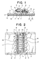
- the laminated synthetic resin film 4 With the laminated synthetic resin film 4 disposed such that the low melting point resin layer 12 faces a pair of the fastener tapes 3 on the rear face of the fastener chain 1 as shown in Fig. 1, the laminated synthetic resin film 4 is heated under pressure so as to be fused to an entire surface of the fastener tape 3. Then, the laminated synthetic resin film 4 disposed so as to span between the side edges 11 of the right and left fastener tapes 3 is cut between the side edges 11 so as to form the fastener chain 1.
- the cut laminated synthetic resin film 4 protrudes from the side edge 11 of each fastener tape 3. Further, when coupling heads 14 of the right and left coil-shaped fastener elements 5 couple with each other, the cut laminated synthetic resin films 4 protrude from a center point of the coupling. Therefore, when the coil-shaped fastener elements 5 of the right and left fastener stringers 2 couple with each other, the laminated synthetic resin films 4 protruding from the side edge 11 of the fastener tape 3 collide with the mating one thereby achieving waterproof function.
- this fastener chain is sewn onto an object to be attached, with a side in which the laminated synthetic resin film 4 is fused being a front side and the side in which the coil-shaped fastener elements 5 are attached being a rear side.
- the laminated synthetic resin film 4 may be transparent or semi-transparent and in this case, a color of the fastener tape 3 can be seen through the film. Further, it is also permissible to provide this laminated synthetic resin film 4 with unevenness pattern or fabric pattern by embossing the surface of the high melting point resin layer 13. As a result, the surface of the laminated synthetic resin film 4 can be matted and adhesion performance thereof to the object to be attached is improved.
- the fastener chain 1 is wound around a bobbin supported by a supporting shaft 31 acting as a fastener chain supplying portion 22 and introduced between a heating roller 25 journaled by a rotation shaft 29 and a pressure roller 26 journaled by a rotation shaft 28. Finally, the fastener chain 1 is wound up around a winding roller 24 journaled by a driving shaft 33.
- the laminated synthetic resin film 4 wound around a bobbin supported by a supporting shaft 32 provided as a laminated synthetic resin film supplying portion 23 separately from the fastener chain supplying portion 22 is transferred to between the heating roller 25 and pressure roller 26.
- the fastener chain 1 and the laminated synthetic resin film 4 pass between the heating roller 25 and pressure roller 26, with the fastener chain 1 and the low melting point resin layer 12 of the laminated synthetic resin film 4 opposing each other in contact, so that the low melting point resin layer 12 is melted by the heating roller 25 and the pressure roller 26 and fused to the fastener tape 3.
- the laminated synthetic resin film 4 is mounted to the fastener chain 1.
- the laminated synthetic resin film 4 which spans between the side edges 11 opposing each other of the fastener tapes 3 is cut in the center between the side edges 11 by a cutter 30 disposed in a cutting portion 21.
- the integral fastener chain 1 can be separated to right and left fastener stringers 2.
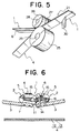
- a concave groove portion 27 is provided in the surface of the pressure roller 26 as shown in Fig. 5 so that the coupled coil-shaped fastener elements 5 of the fastener chain 1 are inserted therein and guided thereby. Further, because only the low melting point resin layer 12 is melted and bonded while the high melting pint resin layer 13 is not melted when the laminated synthetic resin film 4 is fused, the perforation phenomenon due to heating under pressure is not generated so that the surface is kept smooth.
- a step of fusing the laminated synthetic resin film 4 to the fastener chain 1 shown in Fig. 6 has a feature in that the fastener tape 3 and laminated synthetic resin film 4 are bonded together such that a slightly larger amount of the laminated synthetic resin film 4 exists between the side edges 11 opposing each other of the right and left fastener tapes 3 in the fastener chain 1 as compared to the above described example in order to intensify waterproof. That is, the surface of the pressure roller 26 shown in Fig. 5 is formed in a mountain shape which protrudes gradually toward the center of the surface and on the other hand, the surface of the heating roller 25, provided so as to oppose the pressure roller 26, is formed in a V shape which deepens gradually toward the center of the surface.
- an interval between the side edges 11 of the right and left fastener tapes 3 is expanded so that the laminated synthetic resin film 4 longer than an ordinary dimension of the interval between the side edges 11 can be disposed so as to span between the side edges 11.
- the cut ends of the laminated synthetic resin film 4 collide with each other firmly to close the gap thereby preventing water leakage between the cut ends. Consequently, the waterproof effect at the side edges 11 of the fastener tapes 3 can be intensified. Meanwhile, it is permissible to expand the interval between the side edges 11 of the fastener chain 1 by pulling the fastener tapes 3 to the right and left in the fastener chain 1 in which the right and left fastener stringers 2 couple with each other.
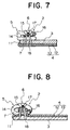
- Fig. 7 shows a modification of the linear fastener elements 5.
- synthetic resin monofilament is formed in zigzag shape and a center point of the elements is bent.
- so-called the zigzag type i.e., the zigzag shaped fastener elements 5 are sewn onto the surface of the side edge 11 of the fastener tape 3.
- the core thread 7 is interposed and held between upper and lower leg portions 15 and this core thread 7 is sewn with the sewing yarns 6 of the multi-thread chain stitch.
- the right and left fastener stringers 2 are coupled with each other to form the fastener chain 1 and then, the laminated synthetic resin film 4 is fused to the entire surface of the rear face of the fastener chain 1. Next, the fused laminated synthetic resin film 4 is cut between the side edges 11 of the right and left fastener tapes 3 so that the fastener chain 1 is separable to the right and left portions. In this fastener stringer 2 also, the side of the laminated synthetic resin film 4 is exposed outside.
- the laminated synthetic resin film 4 is fused on the side in which the coil-shaped fastener elements 5 are sewn.
- the two-layer laminated synthetic resin film 4 composed of the low melting point resin layer 12 and high melting point resin layer 13 is disposed on the surface of the fastener tape 3, and it is placed such that the low melting point resin layer 12 opposes the fastener tape 3 and fused thereto by heating under pressure.
- the laminated synthetic resin film 4 is fused such that it protrudes from the side edge 11 of the fastener tape 3.
- the fastener stringer 2 is completed.
- the coil-shaped fastener element 5 is attached to an object to be attached so that it is exposed on the front surface of the object.
- the coil-shaped fastener elements 5 are sewn onto the front surface of the side edge 11 of the fastener tape 3 with the sewing yarns 6, and the rear surface of the fastener tape 3 at a portion of the sewing yarns 6 is coated with synthetic resin sealing agent 9 or synthetic resin paint 9 to prevent water leakage along the sewing yarns 6 to the rear surface of the fastener tape 3.
- synthetic resin sealing agent 9 or synthetic resin paint 9 to prevent water leakage along the sewing yarns 6 to the rear surface of the fastener tape 3.
- the coil-shaped fastener elements 5 are sewn with the sewing yarns 6 onto the front surface of the side edge 11 of the fastener tape 3 whose surface is coated with the laminated synthetic resin film 4.
- a synthetic resin film 8 is bonded or fused to the rear surface of this fastener tape 3 at the portion of the sewing yarns 6 so as to intensify the waterproof effect. Meanwhile, it is permissible to make an end of the synthetic resin film 8 in contact with the laminated synthetic resin film 4.
- the laminated synthetic resin film 4 is disposed entirely on the front and rear surfaces of the fastener tape 3 and fused to the fastener tape 3 by heating under pressure. Then, the coil-shaped fastener elements 5 are sewn with the sewing yarns 6 onto the surface of the side edge 11 of the fastener tape 3 whose front and rear surfaces are covered with the laminated synthetic resin film 4. Then, the laminated synthetic resin film 4 is fused to the fastener tape 3 such that the ends thereof protrude across a center point in which the right and left coil-shaped fastener elements couple with each other, so as to prevent water leakage along a colliding face of the right and left fastener stringers 2.
- a hot melting yarn is used as a needle yarn 18 of the sewing yarns 6 of the multi-thread chain stitch.
- the needle yarn 18 is melted by heating so that it is fused to the laminated synthetic resin film 4 or the melted yarn buries a gap around the needle yarn 18 so as to prevent water leakage around the needle yarn 18. Meanwhile, it is permissible to use the hot melting yarn for a looper yarn 17.
- the laminated synthetic resin film 4 composed of the low melting point resin layer 12 and high melting point resin layer 13 is fused to the entire surface of the fastener tape 3.
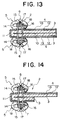
- a pair of the coil-shaped fastener elements 5 are disposed on the laminated synthetic resin film 4 fused to the fastener tape 3 so as to oppose each other across a predetermined interval, that is, sewn with the sewing yarns 6 of the multi-thread chain stitch such that the coupling heads 14 oppose each other with the predetermined interval.
- the fastener tape 3 is folded back in the gap between the pair of the coil-shaped fastener elements 5 so that the two folded portions are overlaid and the opposing faces of the fastener tape 3 are bonded to each other by synthetic resin adhesive agent 10.
- the coil-shaped fastener elements 5 exist on both the front and rear surfaces of the fastener stringer 2.
- the fastener stringer 2 of a modification of the third embodiment shown in Fig. 14 by restricting the overlaying portion of the fastener tape 3 in the fastener stringer 2 shown in Fig. 13 to a portion in which the coil-shaped fastener elements 5 are sewn, reduction of the material cost is intended. Further, the fastener stringer 2 of another modification shown in Fig. 15 is so formed that when the right and left coil-shaped fastener elements 5 couple with each other, the end edges of the laminated synthetic resin film 4 fused to the fastener tape 3 protrude slightly from the center point of the coupling.
- the coil-shaped linear fastener elements 5 are attached to the side edge 11 of the fastener tape 3 by weaving in at the time of weaving the fastener tape 3.
- the laminated synthetic resin film 4 composed of the low melting point resin layer 12 and high melting point resin layer 13 is fused to the rear surface of the fastener tape 3 such that it protrudes from the side edge 11 of the fastener tape 3. Meanwhile, it is permissible to attach the coil-shaped linear fastener elements 5 to the side edge 11 by knitting and fuse the laminated synthetic resin film 4 to the rear surface of the fastener tape 3.
- a swollen core portion 7a is formed on the side edge 11 of the fastener tape 3 and a metallic discrete fastener element 5 is attached by crimping to the core portion 7a.
- the laminated synthetic resin film 4 composed of the low melting point resin layer 12 and high melting point resin layer 13 is fused to the rear surface of the fastener tape 3 such that it protrudes from the side edge 11 of each of a pair of the fastener tapes 3.
- the laminated synthetic resin films 4 fused to each of the fastener tapes 3 collide with each other between the side edges 11. It is also permissible to attach a discrete fastener element of synthetic resin directly to the core portion 7a by injection molding means.
- Fig. 18 shows a modification of the laminated synthetic resin film 4.
- a synthetic resin layer 20 is further disposed on the surface of the high melting point resin layer 13.
- the melting point of the low melting point resin layer 12 is 100 °C - 150 °C
- that of the high melting point resin layer 13 is 150 °C - 200 °C
- that of the synthetic resin layer 20 is 200 °C - 220 °C.
- the synthetic resin layer 20 is disposed appropriately depending on an application of the fastener chain.
- the synthetic resin layer 20 may have a melting point higher than 220 °C, provided with unevenness pattern or fabric pattern on the surface thereof by embossing or the like or provided with a ultraviolet ray protecting function.
- the laminated synthetic resin film 4 composed of low melting point resin layer 12 and high melting point resin layer 13 is fused to at least one surface of the fastener tape 3 in the slide fastener such that the low melting point resin layer 12 is in contact with and opposes the surface of the fastener tape 3 while the fastener elements 5 are mounted on the side edge 11 of the fastener tape 3.
- the laminated synthetic resin film 4 can be fused to the fastener tape 3 securely so as to provide the fastener tape 3 with waterproofness and prevent an occurrence of a portion in which the synthetic resin film does not exist locally due to heating the surface of the synthetic resin film or due to threading of the sewing yarns, namely, an occurrence of perforation phenomenon.
- a slide fastener having an good appearance is obtained.
- the melting points of the low melting point resin layer 12 and high melting point resin layer 13 in the laminated synthetic resin film 4 are specified.
- the laminated synthetic resin film 4 never peels from the fastener tape 3 upon dry cleaning and can be fused to the fastener chain securely and easily.
- the laminated synthetic resin film 4 to be fused to the fastener tape 3 is formed so as to protrude from the side edge 11 of the fastener tape 3 and the center point of coupling of the fastener elements 5.
- waterproof function at the side edges 11 in which the right and left fastener tapes 3 collide with each other can be achieved with a simple structure.
- the fastener elements 5 are mounted on the front surface of the side edge 11 of the fastener tape 3 and the laminated synthetic resin film 4 is fused on the rear surface of the fastener tape 3.
- the fastener chain 1 in which the slide fastener is mounted on the rear surface thereof with waterproof function with a simple structure.
- the laminated synthetic resin film 4 is fused on the front surface of the fastener tape 3 and the fastener elements 5 are mounted on the front surface of the side edge 11 of the fastener tape 3.
- the fastener chain 1 in which the slide fastener is mounted on the front surface thereof with waterproof function with a simple structure.
- the laminated synthetic resin film 4 is fused on the front surface of the fastener tape 3 and linear fastener elements 5 are sewn onto the front surface of the side edge 11 of the fastener tape 3 while the rear surface of the portion to which the fastener elements 5 are sewn is treated with waterproof finish.
- the laminated synthetic resin film 4 is fused on the front surface of the fastener tape 3 and linear fastener elements 5 are sewn onto the front surface of the side edge 11 of the fastener tape 3 while sewing yarns 6 with which the fastener elements 5 are fixed are treated with waterproof finish.
- water leakage or water penetration along the portion of the sewing yarns 6 for fixing the fastener elements 5 in the fastener chain 1 in which the slide fastener is mounted on the front surface can be prevented securely and easily by modification on the sewing yarns so as to intensify the water resisting effect.
- the laminated synthetic resin film 4 is fused on the surface of the fastener tape 3, a pair of the linear fastener elements 5 are disposed on the surface such that they oppose with their coupling heads opposing each other across a predetermined interval, the fastener tape 3 is bent at the middle between the pair of the linear fastener elements 5 so that the bent portions overlap, while the overlapping faces of the fastener tape 3 are bonded to each other.
- this slide fastener has fastener elements 5 on both surfaces of the fastener tape 3. Water leakage or water penetration in the side edge 11 in which the fastener stringers 2 collide with each other can be prevented securely with a simple structure so that airtightness and watertightness can be secured.
- fastener elements 5 are mounted on the surface of the side edge 11 of each of the pair of fastener tapes 3; the right and left linear fastener elements 5 are coupled with each other, and then the laminated synthetic resin film 4 composed of low melting point resin layer 12 and high melting point resin layer 13 is heated under pressure onto the rear surface of each of the pair of combined fastener tapes, with the low melting point resin layer 12 being in contact with and opposing the fastener tape 3, so as to fuse the low melting point resin layer 12 to the fastener tape 3; the laminated synthetic resin film 4 is cut between the right and left fastener tapes 3 so as to produce a fastener chain 1.
- the laminated synthetic resin film 4 can be fused securely to the fastener tape 3, so that a slide fastener having a good appearance can be produced easily with a simple manufacturing process.
- the fastener elements 5 are kept with a gap between opposing side edges 11 thereof by pulling the right and left fastener tapes 3 to the right and left or arranging the fastener elements in a mountain shape to project toward the fastener tape side while the laminated synthetic resin film 4 is fused to the fastener tapes.
- the waterproof function between the side edges 11 of the fastener tape 3 can be intensified by a simple manufacturing process. That is, the effects of the present invention are quite remarkable.
Landscapes
- Slide Fasteners (AREA)
- Bag Frames (AREA)
- Laminated Bodies (AREA)
Applications Claiming Priority (2)
| Application Number | Priority Date | Filing Date | Title |
|---|---|---|---|
| JP12355799 | 1999-04-30 | ||
| JP12355799A JP3580725B2 (ja) | 1999-04-30 | 1999-04-30 | 防水性を有するスライドファスナーの製造方法 |
Publications (2)
| Publication Number | Publication Date |
|---|---|
| EP1048237A1 true EP1048237A1 (de) | 2000-11-02 |
| EP1048237B1 EP1048237B1 (de) | 2003-07-02 |
Family
ID=14863550
Family Applications (1)
| Application Number | Title | Priority Date | Filing Date |
|---|---|---|---|
| EP00107991A Expired - Lifetime EP1048237B1 (de) | 1999-04-30 | 2000-04-18 | Wasserdichter Reissverschluss und Verfahren zu dessen Herstellung |
Country Status (8)
| Country | Link |
|---|---|
| US (1) | US6427294B1 (de) |
| EP (1) | EP1048237B1 (de) |
| JP (1) | JP3580725B2 (de) |
| KR (1) | KR100385526B1 (de) |
| CN (1) | CN1150841C (de) |
| DE (1) | DE60003607T2 (de) |
| ES (1) | ES2200749T3 (de) |
| TR (1) | TR200001130A2 (de) |
Cited By (10)
| Publication number | Priority date | Publication date | Assignee | Title |
|---|---|---|---|---|
| EP1537801A4 (de) * | 2002-06-20 | 2006-11-29 | Ykk Corp | Anschlagst ck f r gleitverschluss und gleitverschluss mit einem derartigen anschlagst ck |
| EP1908365A1 (de) * | 2006-10-04 | 2008-04-09 | Riri Group S.A. | Fluiddichter Reißverschluss |
| EP1908364A1 (de) * | 2006-10-04 | 2008-04-09 | Riri Group S.A. | Luft- und wasserdichter Reissverschluss |
| EP2044855A1 (de) * | 2007-10-04 | 2009-04-08 | Riri Group S.A. | Fluiddichter Reißverschluss |
| WO2009068848A3 (en) * | 2007-11-30 | 2009-09-24 | Ykk Europe Limited | Zip fastener |
| ITTO20091041A1 (it) * | 2009-12-24 | 2011-06-25 | Ykk Italia S P A | Cerniera-lampo |
| EP2274997A3 (de) * | 2009-07-13 | 2014-04-30 | YKK Corporation | Reißverschluss |
| EP3384799A4 (de) * | 2015-12-02 | 2019-07-03 | YKK Corporation | Reissverschlussbandglied und bandgliedherstellungsverfahren |
| EP4046524A4 (de) * | 2019-10-16 | 2022-10-12 | Ykk Corporation | Verwobene verschlussleiste, reissverschluss und verfahren zum herstellen der verwobenen verschlussleiste |
| EP4151115A4 (de) * | 2020-09-18 | 2023-10-25 | Kee (Hubei) Zippers Manufacturing Limited | Verbesserter verschlussstringer, reissverschluss, hautprodukt und herstellungsverfahren dafür |
Families Citing this family (67)
| Publication number | Priority date | Publication date | Assignee | Title |
|---|---|---|---|---|
| US6936121B2 (en) * | 2002-06-25 | 2005-08-30 | Riri S.A. | Method of sealing the join between a zip and a garment with a lining |
| TWI220106B (en) * | 2003-05-27 | 2004-08-11 | Sun Yen Ping | Method for producing zipper with waterproof layer lined in the cloth belt and product thereof |
| US20070094852A1 (en) * | 2003-05-27 | 2007-05-03 | Yen-Ping Sun | Waterproof zipper |
| KR100557889B1 (ko) * | 2003-12-01 | 2006-03-10 | 차동준 | 방수성 재질로된 지퍼 체인의 제조방법 |
| US20060282995A1 (en) * | 2005-06-20 | 2006-12-21 | Eddy Liou | Water-tight and air-tight zipper |
| JP2007023421A (ja) * | 2005-07-15 | 2007-02-01 | Shimano Inc | 衣服 |
| US7392572B2 (en) * | 2006-04-03 | 2008-07-01 | Riri Group S.A. | Fluidtight slide fastener |
| CN100593377C (zh) * | 2007-01-23 | 2010-03-10 | 上海东龙服饰有限公司 | 防水拉链加工装置 |
| JP4689631B2 (ja) * | 2007-02-08 | 2011-05-25 | Ykk株式会社 | 液密スライドファスナー並びに液密スライドファスナーの製造方法 |
| US8001618B2 (en) | 2007-09-21 | 2011-08-23 | Sullivans, Inc. | Ventilated double-closure garment |
| US8336116B2 (en) | 2008-04-28 | 2012-12-25 | Angela Jodie Gomes Seguin | Garment closure system |
| US8397353B2 (en) * | 2008-11-26 | 2013-03-19 | Chao-Mu Chou | Continuous-coil type waterproof slide fastener and the structure impervious to fluid thereof |
| KR101372717B1 (ko) * | 2008-12-22 | 2014-03-11 | 컬럼비아 스포츠웨어 노스 아메리카, 인크. | 내후성 슬라이드 파스너 |
| US9089187B2 (en) * | 2009-09-11 | 2015-07-28 | Ykk Corporation | Fastener stringer for concealed slide fastener |
| KR101325441B1 (ko) * | 2009-11-30 | 2013-11-04 | 와이케이케이 가부시끼가이샤 | 액밀 슬라이드 파스너 및 그 제조 방법 |
| GB201012592D0 (en) | 2010-07-27 | 2010-09-08 | Ykk Europ Ltd | Zip fastener |
| CN103096750B (zh) * | 2010-09-17 | 2015-08-26 | Ykk株式会社 | 拉链以及拉链的制造方法 |
| US20130174767A1 (en) * | 2010-09-29 | 2013-07-11 | Ykk Corporation | Fastener Stringer Provided with Knit Tape |
| ES2644287T3 (es) * | 2010-12-17 | 2017-11-28 | Ykk Corporation | Banda de cierre y cadena de cierre de cremallera, y procedimiento de fabricación de la cadena de cierre de cremallera |
| JP5228147B2 (ja) * | 2011-02-07 | 2013-07-03 | リリ エッセ アー | 接合されるテープに溶着された歯を備える封止用スライドファスナ |
| KR101236339B1 (ko) * | 2011-03-23 | 2013-03-04 | 윤여산 | 퍼커링홀이 형성된 슬라이드파스너의 제조방법 및 퍼커링홀 성형장치 |
| JP5813122B2 (ja) * | 2011-09-21 | 2015-11-17 | Ykk株式会社 | スライドファスナー |
| ITTO20111070A1 (it) * | 2011-11-22 | 2013-05-23 | Ykk Italia S P A | Cerniera lampo. |
| JP6047285B2 (ja) * | 2011-12-20 | 2016-12-21 | Ykk株式会社 | ファスナーストリンガー、カバン用スライドファスナー、及びカバン |
| CN102697254A (zh) * | 2012-04-17 | 2012-10-03 | 立兆股份有限公司 | 防水拉链及其制作工艺 |
| JP5981547B2 (ja) | 2012-07-09 | 2016-08-31 | Ykk株式会社 | ファスナーテープ、当該ファスナーテープを備えたスライドファスナー、及びファスナーテープの製造方法 |
| JP3179861U (ja) * | 2012-09-10 | 2012-11-22 | Ykk株式会社 | スライドファスナー |
| WO2014118948A1 (ja) * | 2013-01-31 | 2014-08-07 | Ykk株式会社 | スライドファスナー付き物品及びスライドファスナー付き物品の製造方法 |
| CN103271517B (zh) * | 2013-06-04 | 2015-06-24 | 芊茂(浙江)拉链有限公司 | 三防的高强度双层齿拉链及其制作方法 |
| JP3186907U (ja) * | 2013-08-19 | 2013-10-31 | ▲せん▼茂拉鏈股▲ふん▼有限公司 | 防水、気密、破裂防止、割裂防止機能を備える横方向強度が極めて高い二層務歯ファスナー |
| ITTO20130789A1 (it) | 2013-10-02 | 2015-04-03 | Ykk Europ Ltd | Nastri per cerniere lampo e procedimento per la loro fabbricazione |
| TWI507145B (zh) * | 2013-10-24 | 2015-11-11 | Fabrication method and structure of double - layer tooth opening zipper and triple play zipper | |
| KR101370778B1 (ko) * | 2013-11-15 | 2014-03-06 | 정지옹 | 유연성이 높고 지퍼 물림성이 양호한 합성수지제 지퍼 |
| JP6281899B2 (ja) * | 2013-12-27 | 2018-02-21 | グローブライド株式会社 | 上着 |
| US10781028B2 (en) * | 2014-02-07 | 2020-09-22 | Yeti Coolers, Llc | Insulating device backpack |
| US10384855B2 (en) | 2014-02-07 | 2019-08-20 | Yeti Coolers, Llc | Insulating device and method for forming insulating device |
| US9139352B2 (en) | 2014-02-07 | 2015-09-22 | Yeti Coolers, Llc | Insulating container |
| USD787187S1 (en) | 2014-09-23 | 2017-05-23 | Yeti Coolers, Llc | Insulating device |
| JP6340435B2 (ja) * | 2014-12-25 | 2018-06-06 | Ykk株式会社 | スライドファスナーチェーン、当該ファスナーチェーンを備えたスライドファスナー及びスライドファスナーチェーンの製造方法 |
| WO2017079315A1 (en) * | 2015-11-02 | 2017-05-11 | Yeti Coolers, Llc | Closure systems and insulating devices having closure systems |
| US10981716B2 (en) | 2016-02-05 | 2021-04-20 | Yeti Coolers, Llc | Insulating device |
| US12012274B2 (en) | 2016-02-05 | 2024-06-18 | Yeti Coolers, Llc | Insulating device backpack |
| US9918527B2 (en) | 2016-03-31 | 2018-03-20 | Ykk Corporation | Concealable slide fastener |
| USD805851S1 (en) | 2016-06-01 | 2017-12-26 | Yeti Coolers, Llc | Cooler |
| CN109195475B (zh) * | 2016-07-01 | 2021-08-03 | Ykk株式会社 | 拉链带、具备该拉链带的拉链以及拉链带的制造方法 |
| US10264858B2 (en) * | 2016-08-26 | 2019-04-23 | Win-Chain Knitting Co., Ltd. | Waterproof zipper and process of manufacturing same |
| TW201815310A (zh) * | 2016-10-24 | 2018-05-01 | 周朝木 | 具連續式扣合元件之拉鏈 |
| CN108244774B (zh) * | 2016-12-29 | 2021-06-11 | Ykk株式会社 | 薄膜分割器、拉链链条的制造装置和方法及薄膜分割方法 |
| TWI616155B (zh) * | 2017-01-23 | 2018-03-01 | 冠宇拉鍊股份有限公司 | 阻水拉鍊及其製造方法 |
| CN110545689B (zh) * | 2017-03-09 | 2022-03-25 | Ykk株式会社 | 带拉链的产品及带拉链的产品的制造方法 |
| CN107157031B (zh) * | 2017-06-20 | 2021-03-05 | 刘科军 | 双锁式防水防风拉链 |
| TWI619445B (zh) * | 2017-08-07 | 2018-04-01 | 冠宇拉鍊股份有限公司 | 防水拉鍊布及其防水拉鍊 |
| JP6980557B2 (ja) * | 2018-02-19 | 2021-12-15 | Ykk株式会社 | ファスナーストリンガー、スライドファスナーおよびファスナーストリンガー取付構造 |
| TWI662915B (zh) * | 2018-03-12 | 2019-06-21 | 日商Ykk股份有限公司 | zipper |
| CN108497630A (zh) * | 2018-04-03 | 2018-09-07 | 上海金星拉链有限公司 | 拉链剥面机 |
| TWI680729B (zh) * | 2018-09-13 | 2020-01-01 | 日商Ykk股份有限公司 | 隱藏式拉鏈半成品、隱藏式拉鏈安裝成品以及隱藏式拉鏈安裝成品的製造方法 |
| WO2020054015A1 (ja) * | 2018-09-13 | 2020-03-19 | Ykk株式会社 | 隠しスライドファスナー半製品、隠しスライドファスナー取付製品及び隠しスライドファスナー取付製品を製造する方法 |
| CN111374399A (zh) * | 2018-12-26 | 2020-07-07 | Ykk株式会社 | 拉链链牙带和拉链链牙带的制造方法 |
| JP6876110B2 (ja) * | 2019-10-04 | 2021-05-26 | Ykk株式会社 | スライドファスナー |
| TWI791908B (zh) | 2019-10-09 | 2023-02-11 | 周朝木 | 防滲拉鏈及其製法 |
| US11242189B2 (en) | 2019-11-15 | 2022-02-08 | Yeti Coolers, Llc | Insulating device |
| US11363860B2 (en) | 2019-11-23 | 2022-06-21 | Talon Technologies, Inc. | Waterproof curved zippers |
| EP4061178A4 (de) | 2019-11-23 | 2023-12-13 | Talon Technologies Inc. | Gekrümmter reissverschluss |
| JP7762568B2 (ja) * | 2019-12-12 | 2025-10-30 | Ykk株式会社 | 止水ファスナとその製造方法 |
| US20240341416A1 (en) * | 2021-07-27 | 2024-10-17 | Ykk Corporation | Fastener chain and sliding fastener |
| JP2024053380A (ja) | 2022-10-03 | 2024-04-15 | Ykk株式会社 | スライドファスナー及び止水チェーンの製造方法 |
| JP2024053379A (ja) * | 2022-10-03 | 2024-04-15 | Ykk株式会社 | スライドファスナー及び止水チェーンの製造方法 |
Citations (6)
| Publication number | Priority date | Publication date | Assignee | Title |
|---|---|---|---|---|
| US4233099A (en) * | 1978-12-20 | 1980-11-11 | Textron Inc. | Slide fastener method of manufacture |
| EP0111889A2 (de) * | 1982-12-15 | 1984-06-27 | Yoshida Kogyo K.K. | Wasserdichter Reissverschluss und Verfahren zur Herstellung |
| EP0111788A2 (de) * | 1982-12-14 | 1984-06-27 | Yoshida Kogyo K.K. | Wasserdichter Reissverschluss und Verfahren zur Herstellung |
| EP0162350A2 (de) * | 1984-05-19 | 1985-11-27 | Yoshida Kogyo K.K. | Verfahren zum Herstellen eines luftdichten und wasserdichten Reissverschlusses |
| EP0164610A2 (de) * | 1984-06-13 | 1985-12-18 | Yoshida Kogyo K.K. | Flüssigkeitsdichter Reissverschluss |
| WO2000018270A1 (en) * | 1998-09-25 | 2000-04-06 | Hoder, Harold | Water resistant slide fastener and process for preparing same |
Family Cites Families (9)
| Publication number | Priority date | Publication date | Assignee | Title |
|---|---|---|---|---|
| NO119295B (de) * | 1966-10-15 | 1970-04-27 | Opti Holding Ag | |
| GB1167778A (en) * | 1967-08-18 | 1969-10-22 | Opti Holding Ag | Improvements in or relating to stringers for sliding clasp fasteners. |
| JPS5578905A (en) * | 1978-12-07 | 1980-06-14 | Yoshida Kogyo Kk | Slide fastener |
| US4350721A (en) * | 1981-11-17 | 1982-09-21 | Nagase Rubber Co., Ltd. | Collapsible indoor sports mats |
| JPS5921208U (ja) * | 1982-08-02 | 1984-02-09 | ワイケイケイ株式会社 | スライドフアスナ− |
| JPS6175712U (de) * | 1984-10-25 | 1986-05-22 | ||
| JP3463114B2 (ja) * | 1995-04-29 | 2003-11-05 | Ykk株式会社 | スライドファスナーの補強テープ |
| US6231979B1 (en) * | 1996-11-22 | 2001-05-15 | Kaneka Corporation | Self-fusible insulated wire |
| JPH10243807A (ja) * | 1997-03-07 | 1998-09-14 | Ykk Corp | スライドファスナーの補強テープ |
-
1999
- 1999-04-30 JP JP12355799A patent/JP3580725B2/ja not_active Expired - Lifetime
-
2000
- 2000-04-11 US US09/547,062 patent/US6427294B1/en not_active Expired - Lifetime
- 2000-04-18 EP EP00107991A patent/EP1048237B1/de not_active Expired - Lifetime
- 2000-04-18 ES ES00107991T patent/ES2200749T3/es not_active Expired - Lifetime
- 2000-04-18 DE DE60003607T patent/DE60003607T2/de not_active Expired - Lifetime
- 2000-04-26 TR TR2000/01130A patent/TR200001130A2/xx unknown
- 2000-04-26 CN CNB00108268XA patent/CN1150841C/zh not_active Expired - Lifetime
- 2000-04-26 KR KR10-2000-0022104A patent/KR100385526B1/ko not_active Expired - Fee Related
Patent Citations (6)
| Publication number | Priority date | Publication date | Assignee | Title |
|---|---|---|---|---|
| US4233099A (en) * | 1978-12-20 | 1980-11-11 | Textron Inc. | Slide fastener method of manufacture |
| EP0111788A2 (de) * | 1982-12-14 | 1984-06-27 | Yoshida Kogyo K.K. | Wasserdichter Reissverschluss und Verfahren zur Herstellung |
| EP0111889A2 (de) * | 1982-12-15 | 1984-06-27 | Yoshida Kogyo K.K. | Wasserdichter Reissverschluss und Verfahren zur Herstellung |
| EP0162350A2 (de) * | 1984-05-19 | 1985-11-27 | Yoshida Kogyo K.K. | Verfahren zum Herstellen eines luftdichten und wasserdichten Reissverschlusses |
| EP0164610A2 (de) * | 1984-06-13 | 1985-12-18 | Yoshida Kogyo K.K. | Flüssigkeitsdichter Reissverschluss |
| WO2000018270A1 (en) * | 1998-09-25 | 2000-04-06 | Hoder, Harold | Water resistant slide fastener and process for preparing same |
Cited By (17)
| Publication number | Priority date | Publication date | Assignee | Title |
|---|---|---|---|---|
| US7231697B2 (en) | 2002-06-20 | 2007-06-19 | Ykk Corporation | End stop for slide fastener and slide fastener having the same |
| EP1537801A4 (de) * | 2002-06-20 | 2006-11-29 | Ykk Corp | Anschlagst ck f r gleitverschluss und gleitverschluss mit einem derartigen anschlagst ck |
| CN100479691C (zh) * | 2002-06-20 | 2009-04-22 | Ykk株式会社 | 用于拉链的止码部和具有该止码部的拉链 |
| RU2429771C2 (ru) * | 2006-10-04 | 2011-09-27 | Рири Груп С.А. | Герметичная застежка-молния |
| EP1908365A1 (de) * | 2006-10-04 | 2008-04-09 | Riri Group S.A. | Fluiddichter Reißverschluss |
| EP1908364A1 (de) * | 2006-10-04 | 2008-04-09 | Riri Group S.A. | Luft- und wasserdichter Reissverschluss |
| AU2007221736B2 (en) * | 2006-10-04 | 2013-05-23 | Riri Sa | A fluid-tight slide fastener |
| EP2044855A1 (de) * | 2007-10-04 | 2009-04-08 | Riri Group S.A. | Fluiddichter Reißverschluss |
| WO2009068848A3 (en) * | 2007-11-30 | 2009-09-24 | Ykk Europe Limited | Zip fastener |
| EP2274997A3 (de) * | 2009-07-13 | 2014-04-30 | YKK Corporation | Reißverschluss |
| ITTO20091041A1 (it) * | 2009-12-24 | 2011-06-25 | Ykk Italia S P A | Cerniera-lampo |
| EP3384799A4 (de) * | 2015-12-02 | 2019-07-03 | YKK Corporation | Reissverschlussbandglied und bandgliedherstellungsverfahren |
| US10863801B2 (en) | 2015-12-02 | 2020-12-15 | Ykk Corporation | Tape member for slide fastener and manufacturing method of tape member |
| EP4046524A4 (de) * | 2019-10-16 | 2022-10-12 | Ykk Corporation | Verwobene verschlussleiste, reissverschluss und verfahren zum herstellen der verwobenen verschlussleiste |
| US12016435B2 (en) | 2019-10-16 | 2024-06-25 | Ykk Corporation | Knitted fastener stringer, fastener chain, and method for manufacturing knitted fastener stringer |
| EP4151115A4 (de) * | 2020-09-18 | 2023-10-25 | Kee (Hubei) Zippers Manufacturing Limited | Verbesserter verschlussstringer, reissverschluss, hautprodukt und herstellungsverfahren dafür |
| US12022918B2 (en) | 2020-09-18 | 2024-07-02 | Kee (Hubei) Zippers Manufacturing Limited | Fastener tape, slide fastener, skin product, and method of forming fastener tape |
Also Published As
| Publication number | Publication date |
|---|---|
| JP2000312604A (ja) | 2000-11-14 |
| JP3580725B2 (ja) | 2004-10-27 |
| US6427294B1 (en) | 2002-08-06 |
| CN1272346A (zh) | 2000-11-08 |
| DE60003607D1 (de) | 2003-08-07 |
| KR100385526B1 (ko) | 2003-05-27 |
| KR20010049294A (ko) | 2001-06-15 |
| CN1150841C (zh) | 2004-05-26 |
| TR200001130A2 (tr) | 2000-12-21 |
| DE60003607T2 (de) | 2004-06-09 |
| EP1048237B1 (de) | 2003-07-02 |
| ES2200749T3 (es) | 2004-03-16 |
| HK1029901A1 (en) | 2001-04-20 |
Similar Documents
| Publication | Publication Date | Title |
|---|---|---|
| EP1048237B1 (de) | Wasserdichter Reissverschluss und Verfahren zu dessen Herstellung | |
| US11089846B2 (en) | Slide fastener-attached product, element member and manufacturing method of slide fastener-attached product | |
| US6877192B2 (en) | Slide fastener and manufacturing method thereof | |
| EP0053639B1 (de) | Warmanklebende Bänder zur Beendigung der Säume von Bekleidung oder anderen Artikeln | |
| KR100475322B1 (ko) | 슬라이드 패스너 | |
| JPS59108502A (ja) | 防水性を有するスライドファスナ− | |
| US20050235466A1 (en) | Slide fastener | |
| EP1537801B1 (de) | Verfahren zur Herstellung eines Gleitverschlusses | |
| US5956818A (en) | Retroreflective filament slide fastner | |
| US6516499B2 (en) | Linear slide fastener and manufacturing method thereof | |
| US20060016052A1 (en) | Slide fastener stringer and method of manufacturing the same | |
| US3874036A (en) | Sliding clasp fasteners | |
| CA2100023C (en) | Top end stop for concealed slide fastener | |
| US7386893B2 (en) | Laminated sewing-free concealed zipper closure for an outwear having one-piece-fabric-slit body and method of making same | |
| US3866275A (en) | Slide fastener installation | |
| JPS5929527Y2 (ja) | スライドフアスナ−用テ−プ | |
| CA1104328A (en) | Slide fastener stringer | |
| HK1029901B (en) | Waterproof slide fastener and manufacturing method thereof |
Legal Events
| Date | Code | Title | Description |
|---|---|---|---|
| PUAI | Public reference made under article 153(3) epc to a published international application that has entered the european phase |
Free format text: ORIGINAL CODE: 0009012 |
|
| AK | Designated contracting states |
Kind code of ref document: A1 Designated state(s): DE ES FR GB IT SE |
|
| AX | Request for extension of the european patent |
Free format text: AL;LT;LV;MK;RO;SI |
|
| 17P | Request for examination filed |
Effective date: 20010208 |
|
| AKX | Designation fees paid |
Free format text: DE ES FR GB IT SE |
|
| GRAH | Despatch of communication of intention to grant a patent |
Free format text: ORIGINAL CODE: EPIDOS IGRA |
|
| GRAH | Despatch of communication of intention to grant a patent |
Free format text: ORIGINAL CODE: EPIDOS IGRA |
|
| GRAA | (expected) grant |
Free format text: ORIGINAL CODE: 0009210 |
|
| AK | Designated contracting states |
Designated state(s): DE ES FR GB IT SE |
|
| REG | Reference to a national code |
Ref country code: GB Ref legal event code: FG4D |
|
| REF | Corresponds to: |
Ref document number: 60003607 Country of ref document: DE Date of ref document: 20030807 Kind code of ref document: P |
|
| REG | Reference to a national code |
Ref country code: SE Ref legal event code: TRGR |
|
| REG | Reference to a national code |
Ref country code: ES Ref legal event code: FG2A Ref document number: 2200749 Country of ref document: ES Kind code of ref document: T3 |
|
| PLBQ | Unpublished change to opponent data |
Free format text: ORIGINAL CODE: EPIDOS OPPO |
|
| PLBI | Opposition filed |
Free format text: ORIGINAL CODE: 0009260 |
|
| PLAB | Opposition data, opponent's data or that of the opponent's representative modified |
Free format text: ORIGINAL CODE: 0009299OPPO |
|
| PLAZ | Examination of admissibility of opposition: despatch of communication + time limit |
Free format text: ORIGINAL CODE: EPIDOSNOPE2 |
|
| ET | Fr: translation filed | ||
| 26 | Opposition filed |
Opponent name: ORTTLEB SPORTARTIKEL GMBH Effective date: 20040401 Opponent name: ARDMEL AUTOMATION LIMITED Effective date: 20040401 |
|
| R26 | Opposition filed (corrected) |
Opponent name: ARDMEL AUTOMATION LIMITED Effective date: 20040401 Opponent name: ORTLIEB SPORTARTIKEL GMBH Effective date: 20040401 |
|
| PLAX | Notice of opposition and request to file observation + time limit sent |
Free format text: ORIGINAL CODE: EPIDOSNOBS2 |
|
| PLBA | Examination of admissibility of opposition: reply received |
Free format text: ORIGINAL CODE: EPIDOSNOPE4 |
|
| PLAX | Notice of opposition and request to file observation + time limit sent |
Free format text: ORIGINAL CODE: EPIDOSNOBS2 |
|
| PLBB | Reply of patent proprietor to notice(s) of opposition received |
Free format text: ORIGINAL CODE: EPIDOSNOBS3 |
|
| PLAB | Opposition data, opponent's data or that of the opponent's representative modified |
Free format text: ORIGINAL CODE: 0009299OPPO |
|
| PLBP | Opposition withdrawn |
Free format text: ORIGINAL CODE: 0009264 |
|
| PLCK | Communication despatched that opposition was rejected |
Free format text: ORIGINAL CODE: EPIDOSNREJ1 |
|
| PLBN | Opposition rejected |
Free format text: ORIGINAL CODE: 0009273 |
|
| STAA | Information on the status of an ep patent application or granted ep patent |
Free format text: STATUS: OPPOSITION REJECTED |
|
| 27O | Opposition rejected |
Effective date: 20110411 |
|
| REG | Reference to a national code |
Ref country code: DE Ref legal event code: R100 Ref document number: 60003607 Country of ref document: DE Effective date: 20110411 |
|
| REG | Reference to a national code |
Ref country code: FR Ref legal event code: PLFP Year of fee payment: 17 |
|
| REG | Reference to a national code |
Ref country code: FR Ref legal event code: PLFP Year of fee payment: 18 |
|
| PGFP | Annual fee paid to national office [announced via postgrant information from national office to epo] |
Ref country code: FR Payment date: 20170313 Year of fee payment: 18 |
|
| PGFP | Annual fee paid to national office [announced via postgrant information from national office to epo] |
Ref country code: ES Payment date: 20170316 Year of fee payment: 18 |
|
| PGFP | Annual fee paid to national office [announced via postgrant information from national office to epo] |
Ref country code: GB Payment date: 20170412 Year of fee payment: 18 |
|
| PGFP | Annual fee paid to national office [announced via postgrant information from national office to epo] |
Ref country code: SE Payment date: 20170411 Year of fee payment: 18 Ref country code: IT Payment date: 20170420 Year of fee payment: 18 |
|
| REG | Reference to a national code |
Ref country code: SE Ref legal event code: EUG |
|
| GBPC | Gb: european patent ceased through non-payment of renewal fee |
Effective date: 20180418 |
|
| PG25 | Lapsed in a contracting state [announced via postgrant information from national office to epo] |
Ref country code: SE Free format text: LAPSE BECAUSE OF NON-PAYMENT OF DUE FEES Effective date: 20180419 |
|
| PG25 | Lapsed in a contracting state [announced via postgrant information from national office to epo] |
Ref country code: GB Free format text: LAPSE BECAUSE OF NON-PAYMENT OF DUE FEES Effective date: 20180418 |
|
| PG25 | Lapsed in a contracting state [announced via postgrant information from national office to epo] |
Ref country code: IT Free format text: LAPSE BECAUSE OF NON-PAYMENT OF DUE FEES Effective date: 20180418 Ref country code: FR Free format text: LAPSE BECAUSE OF NON-PAYMENT OF DUE FEES Effective date: 20180430 |
|
| PGFP | Annual fee paid to national office [announced via postgrant information from national office to epo] |
Ref country code: DE Payment date: 20190402 Year of fee payment: 20 |
|
| REG | Reference to a national code |
Ref country code: ES Ref legal event code: FD2A Effective date: 20190912 |
|
| PG25 | Lapsed in a contracting state [announced via postgrant information from national office to epo] |
Ref country code: ES Free format text: LAPSE BECAUSE OF NON-PAYMENT OF DUE FEES Effective date: 20180419 |
|
| REG | Reference to a national code |
Ref country code: DE Ref legal event code: R071 Ref document number: 60003607 Country of ref document: DE |