EP1048489A1 - Pneumatique pourvu d'une protubérance pour dévier les projections latérales - Google Patents
Pneumatique pourvu d'une protubérance pour dévier les projections latérales Download PDFInfo
- Publication number
- EP1048489A1 EP1048489A1 EP00107344A EP00107344A EP1048489A1 EP 1048489 A1 EP1048489 A1 EP 1048489A1 EP 00107344 A EP00107344 A EP 00107344A EP 00107344 A EP00107344 A EP 00107344A EP 1048489 A1 EP1048489 A1 EP 1048489A1
- Authority
- EP
- European Patent Office
- Prior art keywords
- protuberance
- tire
- profile
- point
- holes
- Prior art date
- Legal status (The legal status is an assumption and is not a legal conclusion. Google has not performed a legal analysis and makes no representation as to the accuracy of the status listed.)
- Granted
Links
- 230000002787 reinforcement Effects 0.000 claims abstract description 34
- 238000005096 rolling process Methods 0.000 claims abstract description 15
- 239000011324 bead Substances 0.000 claims abstract description 14
- 239000007788 liquid Substances 0.000 claims description 5
- XLYOFNOQVPJJNP-UHFFFAOYSA-N water Substances O XLYOFNOQVPJJNP-UHFFFAOYSA-N 0.000 abstract description 11
- 230000003014 reinforcing effect Effects 0.000 abstract description 4
- 239000000203 mixture Substances 0.000 description 7
- 238000009423 ventilation Methods 0.000 description 3
- 238000010438 heat treatment Methods 0.000 description 2
- 238000000465 moulding Methods 0.000 description 2
- 238000004088 simulation Methods 0.000 description 2
- 229920000297 Rayon Polymers 0.000 description 1
- 238000004026 adhesive bonding Methods 0.000 description 1
- -1 compound compounds Chemical class 0.000 description 1
- 238000007599 discharging Methods 0.000 description 1
- 230000001681 protective effect Effects 0.000 description 1
- 239000002964 rayon Substances 0.000 description 1
- 239000002689 soil Substances 0.000 description 1
- 238000004073 vulcanization Methods 0.000 description 1
Images


Classifications
-
- B—PERFORMING OPERATIONS; TRANSPORTING
- B60—VEHICLES IN GENERAL
- B60C—VEHICLE TYRES; TYRE INFLATION; TYRE CHANGING; CONNECTING VALVES TO INFLATABLE ELASTIC BODIES IN GENERAL; DEVICES OR ARRANGEMENTS RELATED TO TYRES
- B60C13/00—Tyre sidewalls; Protecting, decorating, marking, or the like, thereof
- B60C13/02—Arrangement of grooves or ribs
-
- B—PERFORMING OPERATIONS; TRANSPORTING
- B60—VEHICLES IN GENERAL
- B60C—VEHICLE TYRES; TYRE INFLATION; TYRE CHANGING; CONNECTING VALVES TO INFLATABLE ELASTIC BODIES IN GENERAL; DEVICES OR ARRANGEMENTS RELATED TO TYRES
- B60C11/00—Tyre tread bands; Tread patterns; Anti-skid inserts
- B60C11/01—Shape of the shoulders between tread and sidewall, e.g. rounded, stepped or cantilevered
-
- B—PERFORMING OPERATIONS; TRANSPORTING
- B60—VEHICLES IN GENERAL
- B60C—VEHICLE TYRES; TYRE INFLATION; TYRE CHANGING; CONNECTING VALVES TO INFLATABLE ELASTIC BODIES IN GENERAL; DEVICES OR ARRANGEMENTS RELATED TO TYRES
- B60C19/00—Tyre parts or constructions not otherwise provided for
- B60C19/001—Tyres requiring an asymmetric or a special mounting
-
- B—PERFORMING OPERATIONS; TRANSPORTING
- B60—VEHICLES IN GENERAL
- B60C—VEHICLE TYRES; TYRE INFLATION; TYRE CHANGING; CONNECTING VALVES TO INFLATABLE ELASTIC BODIES IN GENERAL; DEVICES OR ARRANGEMENTS RELATED TO TYRES
- B60C3/00—Tyres characterised by the transverse section
- B60C3/04—Tyres characterised by the transverse section characterised by the relative dimensions of the section, e.g. low profile
-
- B—PERFORMING OPERATIONS; TRANSPORTING
- B60—VEHICLES IN GENERAL
- B60C—VEHICLE TYRES; TYRE INFLATION; TYRE CHANGING; CONNECTING VALVES TO INFLATABLE ELASTIC BODIES IN GENERAL; DEVICES OR ARRANGEMENTS RELATED TO TYRES
- B60C3/00—Tyres characterised by the transverse section
- B60C3/06—Tyres characterised by the transverse section asymmetric
-
- B—PERFORMING OPERATIONS; TRANSPORTING
- B60—VEHICLES IN GENERAL
- B60C—VEHICLE TYRES; TYRE INFLATION; TYRE CHANGING; CONNECTING VALVES TO INFLATABLE ELASTIC BODIES IN GENERAL; DEVICES OR ARRANGEMENTS RELATED TO TYRES
- B60C11/00—Tyre tread bands; Tread patterns; Anti-skid inserts
- B60C11/01—Shape of the shoulders between tread and sidewall, e.g. rounded, stepped or cantilevered
- B60C2011/013—Shape of the shoulders between tread and sidewall, e.g. rounded, stepped or cantilevered provided with a recessed portion
-
- Y—GENERAL TAGGING OF NEW TECHNOLOGICAL DEVELOPMENTS; GENERAL TAGGING OF CROSS-SECTIONAL TECHNOLOGIES SPANNING OVER SEVERAL SECTIONS OF THE IPC; TECHNICAL SUBJECTS COVERED BY FORMER USPC CROSS-REFERENCE ART COLLECTIONS [XRACs] AND DIGESTS
- Y10—TECHNICAL SUBJECTS COVERED BY FORMER USPC
- Y10T—TECHNICAL SUBJECTS COVERED BY FORMER US CLASSIFICATION
- Y10T152/00—Resilient tires and wheels
- Y10T152/10—Tires, resilient
- Y10T152/10018—Tires, resilient with splash guards
Definitions
- the invention relates to tires for road vehicles of the heavy goods vehicle type and in particular those of tires which are provided with a device for deflecting projections water side when a vehicle equipped with said tires is traveling on a covered road of water.
- a truck tire is generally composed of two beads intended for be in contact with a mounting rim, a top provided with a tread having a rolling surface intended to come into contact with the ground during taxiing and two sides ensuring the connection between this tread and the beads.
- Such a tire is reinforced by a carcass reinforcement extending from one bead to the other and a crown reinforcement frame located radially outside the carcass reinforcement, this crown reinforcement comprising at least two plies stacked reinforcements, that is to say placed one on top of the other.
- Each ply of the crown reinforcement is generally composed of a plurality of reinforcements arranged so as to make an angle ranging from 0 ° to 70 ° with the circumferential direction, but it is however not excluded that the angle of the reinforcements can be greater than 70 ° .
- the tread of a truck tire is provided with a shaped tread relief elements delimited by cutouts (grooves and / or incisions) intended to ensure, among other things, the tire's grip performance on wet roads.
- the tire has a maximum width dimension L measured at its sidewalls when it is mounted on its mounting wheel and subjected to its nominal conditions of pressure and load use ( L represents the maximum distance between the points of the sidewalls axially furthest apart).
- the objective of the tire according to the invention is to reconcile a good deflection of the flow of liquid sprayed laterally during driving on water-covered ground without causing increase in the operating temperature of the tire in the tread and in particular in the vicinity of the ends of the crown reinforcement plies.
- the proposed solution optimizes the efficiency couple vis-à-vis the projections lateral water and endurance of the top of the tire.
- only the sidewall intended to be mounted on the exterior side of the vehicle is provided with a protuberance according to the invention.
- the angle ⁇ of the protuberance is between 32 ° and 37 ° .
- a truck tire is fitted with a strip of bearing itself provided with a sculpture composed of a plurality of cutouts, the depth is defined according to the desired performance and in particular according to the acceptable wear limit of said strip.
- the distance between the rolling surface of the tire subjected to its nominal conditions of use and the point of the upper profile of each protuberance located radially outermost is at least equal to the maximum admissible depth of wear of the tread.
- the effectiveness of the proposed solution is all the greater as the portion of the tread located in the vicinity of the end of the working plies has the possibility of discharging the calories produced in this region during the rolling of the tire.
- the upper profile of the protuberance is, from the point of connection K with the sidewall profile, formed of a first curvilinear part extending said sidewall profile. radially inwards from said point K so that said profile of the protuberance is, at least in part, located radially inside the extension of the mean profile of the last crown ply.
- the mean direction of the flank profile radially outside said connection point K corresponds to a direction tangent to the flank and passing through the same point K.
- FIG. 1 represents a partial section of a truck tire according to the invention produced in a meridian plane containing the axis of rotation of said tire.
- This tire 1 of dimension 315/70 R 22.5 comprises a crown region 2 connected to a bead part 3 by a sidewall 4 .
- a thickness h of rubber mixture 65 is provided for spacing said ends.
- the reinforcing structure 6 is covered radially outside a tread 21 having a rolling surface 22 of axial width W having, in the cutting plane, an average transverse profile of circular shape whose axially most point outside B corresponds to the connection point with the side profile.
- This protuberance 7 is in the present case produced by molding at the time of molding and vulcanization of the tire 1 ; as a variant, provision could be made to attach this protuberance by gluing to a sidewall of a molded tire without said protuberance.
- the protuberance 7 is limited by an upper surface 71 radially on the outside and by a lower surface 72 radially on the inside, the intersection of said two surfaces taking place along a line whose trace on the cutting plane corresponds to a point C corresponding to the point of the profile of the protuberance 7 located furthest axially (that is to say in a direction parallel to the axis of rotation).
- connection point K is defined as the point of intersection of the flank profile with the extension of the average profile of the last ply 64 of the crown reinforcement; when, as in the example described, there are several intersection points, point K is the axially innermost point.
- the line D1 passing through the point K and tangent to the upper profile of the protuberance 7 makes an angle ⁇ of 123 ° with the line D2 passing through the point K and tangent to the profile of the flank extending the profile radially outwards. of protuberance.
- FIG. 2 a partial view of a variant of a truck tire according to the invention is shown in a meridian section plane.
- the tire 1 ' shown has a crown 2' reinforced by a carcass reinforcement 5 ' , a reinforcement reinforcement 6' surmounted radially outwards by a tread 21 ' .
- the reinforcing frame 6 ′ is constituted by a stack of the same type as that used in the variant described with FIG. 1 and comprising four plies 61 ′ , 62 ′ , 63 ′ , 64 ′ .
- the ply 64 ′ located radially outermost of the crown reinforcement follows an almost circular average profile 11 ′ and passing half the thickness of said ply.
- the tread surface 22 ' of the tread 21' extends axially between two points B ' (corresponding to the axially furthest points which can come into contact with the ground during running under nominal pressure and load conditions).
- the sidewall profile 4 ' is connected to the running surface by an upper part 42' formed by a curved part 421 ' originating at point B' extending radially inwards by a straight part 422 ' making an angle of 35 ° with a direction parallel to the axis of rotation.
- a protuberance 7 ′ is provided on one of the sides 4 ′ to deflect the lateral projections of water during rolling on ground covered with water.
- This protuberance 7 ′ has an upper profile 71 ′ connecting to point K ′ on the upper profile 42 ′ of the sidewall by an arc of a circle 711 ′ of radius r ′ , said upper profile extending axially towards the outside by a part almost straight 712 ' .
- the point K ' is defined as the point of intersection, axially innermost, of the flank profile with the extension of the average profile 11' of the last ply 64 ' of the crown reinforcement.
- the extension of the mean profile 11 ′ with the flank profile also cuts the exterior profile of the protuberance at two other points P1 and P2 situated axially outside relative to the point K ′ .
- the angle ⁇ between the line D2 ' passing through the point K' and tangent to the upper profile 42 ' of the flank and the line D1' passing through the same point K ' and tangent to the upper profile 71' of the protrusion 7 ' is equal to 60 ° .
- the axially outermost point C ' of the protuberance 7' is at a distance from the equatorial plane XX at most equal to half the distance L ' separating the points M' from the axially furthest sidewalls when the tire is subjected to its nominal conditions of pressure and load.
- the distance from point C' to the axis of rotation is strictly greater than the distance from said points M ' relative to the same axis.
- the point of the upper profile of said protrusion located radially outermost is located, when the tire is flattened under its nominal conditions of use, at a distance from the ground at least equal to the depth maximum allowable wear of said tread.
- This maximum depth being in generally less than the maximum depth of the cutouts, it is preferable that the point of the upper profile of each radially outermost protuberance is distant from the ground an amount at least equal to the maximum depth of the carvings.
- each protrusion opening out only on a single upper or lower wall of each protuberance in order to avoid that during rolling on soil covered with water, it can pass through said protuberance.
- each protuberance can be provided with a first series and with a second series of holes, the first series of holes opening only on the upper wall of said protuberance and the second series of holes opening out only on the bottom wall of said protuberance to further increase ventilation and thereby obtain a lowering of the temperature in the protuberance and also in the parts of the tread at near the ends of the top layers.
- excellent ventilation is obtained by performing in each protrusion a plurality of holes opening onto the upper wall and a second plurality of holes opening on the bottom wall, each hole of the first series opening in at minus a hole from the second series.
- the holes opening on the upper wall of the protuberance are oriented in a first medium orientation and the holes opening onto the lower wall of the protuberance are oriented in a second medium orientation, said mean directions being different so as to limit the possibility of the passage of water to the interior of said holes.
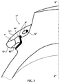
- FIG. 3 shows a partial perspective view of a variant tire 1 '' according to the invention provided with a protuberance 7 '' comprising channels 8 '' opening both on the upper wall 71 '' and the wall lower 72 '' of said protrusion 7 '' .
- Each channel 8 '' consists of a first channel 81 '' of substantially circular cross-section opening onto the upper wall 71 '' , and of a second channel 82 '' also of circular cross-section opening onto the lower wall 72 '' , said two channels 81'' and 82'' being connected together so as to form a bend in the plane of the figure to prevent water from circulating easily inside said channel (the wall limiting each channel forming a screen) .
- this can be formed of a plurality of relief elements regularly spaced in the direction circumferential of the tire, the length of said elements measured in the direction circumferential being at least equal to the distance separating each of said elements in the circumferential direction.
- a protuberance Preferably, only the outer side of a tire intended to be mounted on a heavy-duty vehicle is provided with a protuberance according to the invention. It can also be envisaged equipping only the front axle of a heavy goods vehicle with a tire provided of a protuberance according to the invention.
Landscapes
- Engineering & Computer Science (AREA)
- Mechanical Engineering (AREA)
- Tires In General (AREA)
Abstract
Description
- deux bourrelets destinés à être en contact avec une jante de montage,
- un sommet pourvu d'une bande de roulement présentant une surface de roulement destinée à venir en contact avec le sol pendant le roulage,
- deux flancs assurant la liaison entre cette bande de roulement et les bourrelets,
- une armature de carcasse s'étendant d'un bourrelet à l'autre,
- une armature de renforcement du sommet située radialement à l'extérieur de l'armature de carcasse, cette armature de sommet comprenant au moins deux nappes superposées, chaque nappe étant pourvue de renforts sous la forme de fils ou câbles,
- une protubérance faisant saillie sur au moins l'un des flancs, cette protubérance étant limitée par une paroi supérieure située radialement à l'extérieur et une paroi inférieure située radialement à l'intérieur, l'intersection desdites parois se faisant suivant une ligne joignant les points C de cette protubérance situés axialement le plus à l'extérieur de ladite protubérance, l'angle α, mesuré dans un plan contenant l'axe du pneumatique, entre la direction axiale et une droite tangente à la fois au bord de la bande de roulement et à la protubérance étant inférieur à 45°.
- le point d'intersection C des profils des parois supérieure et inférieure de la protubérance est situé à une distance du plan équatorial XX au plus égale à la moitié de la distance L séparant les points M des flancs axialement les plus éloignés lorsque le pneumatique est soumis à ses conditions nominales de pression et de charge, et la distance du point C à l'axe de rotation est strictement supérieure à la distance desdits points M par rapport au même axe,
- le profil supérieur de la protubérance coupe le profil flanc en un point K, ledit point étant défini comme l'intersection du profil extérieur du pneumatique avec le prolongement du profil moyen de la dernière nappe de l'armature de sommet,
- l'angle δ entre une première droite D1 et une deuxième droite D2 est supérieur ou égal à 60°, la première droite D1 étant définie comme la droite passant par le point K et tangente au profil supérieur de la protubérance et la deuxième droite D2 étant définie comme la droite passant par le point K et tangente au profil du flanc prolongeant radialement vers l'extérieur le profil supérieur de la protubérance à partir dudit point K.
- partie du profil du flanc reliée à l'un des bourrelets,
- partie du profil du flanc reliée à la surface de roulement de la bande de roulement
- profil extérieur de la protubérance situé entre les deux précédents profils.
- la figure 1 montre une coupe méridienne partielle d'un pneumatique pour poids lourd selon l'invention;
- la figure 2 montre une variante de pneumatique selon l'invention;
- la figure 3 montre une variante selon laquelle la protubérance selon l'invention est pourvue d'une pluralité de trous.
- une nappe 63, dite de triangulation, formée d'une pluralité de câbles orientés selon un angle moyen de 65° avec la direction circonférentielle, entre la première nappe de travail 61 et l'armature de carcasse 5, et
- une nappe 64, dite de protection, composée d'une pluralité de câbles orientés selon un angle moyen de 18° avec la direction circonférentielle, ladite nappe 64 étant placée radialement à l'extérieur des nappes de travail. Cette nappe de protection est la nappe située radialement le plus à l'extérieur de l'armature de sommet et suit un profil moyen 11 circulaire passant à mi épaisseur de ladite nappe.
- une partie 42 quasiment rectiligne prenant naissance au point B et s'étendant radialement vers l'intérieur et axialement vers l'extérieur,
- une partie 41 du profil du flanc reliée à l'un des bourrelets 3,
- le profil extérieur de la protubérance 7 reliant les deux précédentes parties de profil flanc.
- une droite passant par le point B axialement le plus à l'extérieur de la surface de roulement 22 et tangente au profil de la protubérance 7 fait avec la direction axiale un angle α égal à 33°;
- le profil méridien de la partie supérieure 71 se raccorde au point K à la partie rectiligne 42 du flanc par un arc de cercle 711 de rayon r égal à 20 mm, ledit arc 711 se prolongeant axialement vers l'extérieur par une partie curviligne 712 parallèle au profil transversal moyen de la surface de roulement 22 du pneumatique à l'état neuf.
- pression : 8.5 bars,
- charge : 3482 daN
- vitesse de roulage : 80 km/h.
| cas A | cas B | cas C |
| 96.6°C | 95.5°C | 98°C |
| cas A | cas B | cas C |
| 110°C | 107°C | 112°C |
Claims (10)
- Pneumatique (1, 1') pour véhicule poids lourd comportant :deux bourrelets (3, 3') destinés à être en contact avec une jante de montage,un sommet (2, 2') pourvu d'une bande de roulement (21, 21') présentant une surface de roulement (22, 22') destinée à venir en contact avec le sol pendant le roulage,deux flancs (4, 4') assurant la liaison entre cette bande de roulement et les bourrelets,une armature de carcasse (5, 5') s'étendant d'un bourrelet à l'autre,une armature de renforcement (6, 6') du sommet située radialement à l'extérieur de l'armature de carcasse, cette armature de sommet comprenant au moins deux nappes de travail (61, 62, 61', 62') pourvues de renforts,une protubérance (7, 7') faisant saillie sur au moins l'un des flancs, cette protubérance étant limitée par une paroi supérieure (71, 71') radialement à l'extérieur et une paroi inférieure (72, 72') radialement à l'intérieur, l'intersection desdites parois se faisant suivant une ligne joignant les points C situés axialement le plus à l'extérieur de ladite protubérance, l'angle α entre la direction axiale et une droite tangente à la fois au bord de la bande de roulement et à la protubérance étant inférieur à 45°,
le pneumatique, vu en coupe méridienne, est caractérisé en ce que :le point d'intersection C des profils des parois supérieure et inférieure (71, 72, 71', 72') de la protubérance (7, 7') est situé à une distance du plan équatorial XX au plus égale à la moitié de la distance L séparant les points M des flancs axialement les plus éloignés lorsque le pneumatique est soumis à ses conditions nominales de pression et de charge, et la distance du point C à l'axe de rotation est strictement supérieure à la distance desdits points M par rapport au même axe,le profil supérieur de la protubérance coupe le profil flanc en un point K défini comme l'intersection du profil extérieur du pneumatique avec le prolongement du profil moyen de la dernière nappe de l'armature de sommet,l'angle δ entre une première droite D1 et une deuxième droite D2 est supérieur ou égal à 60°, la première droite D1 étant définie comme la droite passant par le point K et tangente au profil supérieur de la protubérance et la deuxième droite D2 étant définie comme la droite passant par le point K et tangente au profil du flanc prolongeant radialement vers l'extérieur le profil supérieur de la protubérance à partir dudit point K. - Pneumatique (1, 1') pour véhicule poids lourd selon la revendication 1 caractérisé en ce que, vu dans un plan de coupe méridien contenant l'axe de rotation, la protubérance (7, 7') est telle que l'angle α est compris entre 32° et 37°.
- Pneumatique (1, 1') pour véhicule poids lourd selon la revendication 1 ou la revendication 2 caractérisé en ce que sa bande de roulement (21, 21') est pourvue d'une sculpture formée par une pluralité de découpures et en ce que la distance entre la surface de roulement (22, 22') du pneumatique soumis à ses conditions nominales d'utilisation et le point du profil supérieur de chaque protubérance situé radialement le plus à l'extérieur est au moins égale à la profondeur maximale des découpures de la sculpture.
- Pneumatique (1) pour véhicule poids lourd selon la revendication 3 caractérisé en ce que le profil supérieur (71) de la protubérance (7) est, à partir du point de raccordement K avec le profil flanc, formé d'un premier arc de cercle (711) de rayon r prolongé axialement vers l'extérieur par un profil (712) quasiment parallèle au profil moyen transversal de la surface de roulement (22) de la bande de roulement (21).
- Pneumatique (1'') pour véhicule poids lourd selon l'une des revendications 1 à 4 caractérisé en ce que chaque protubérance (7'') est pourvue d'une pluralité de trous (8''), chacun desdits trous ne débouchant que sur une seule paroi supérieure ou inférieure de ladite protubérance afin de réduire le poids supplémentaire lié à la présence de ladite protubérance.
- Pneumatique (7'') pour véhicule poids lourd selon la revendication 5 caractérisé en ce qu'une première série (81'') et une deuxième série (82'') de trous sont prévues sur au moins une protubérance (7''), la première série de trous (81'') débouchant uniquement sur la paroi supérieure (71'') de ladite protubérance et la deuxième série de trous (82'') débouchant uniquement sur la paroi inférieure (72'') de ladite protubérance.
- Pneumatique pour véhicule poids lourd selon la revendication 6 caractérisé en ce que chaque trou (81'') de la première série débouche dans au moins un trou (82'') de la deuxième série de trous, les trous débouchant sur la paroi supérieure (71'') de la protubérance étant orientés suivant une première orientation moyenne et les trous débouchant sur la paroi inférieure (72'') de la protubérance étant orientés suivant une deuxième orientation moyenne, lesdites directions moyennes étant différentes de façon à limiter le passage de liquide à l'intérieur desdits trous pendant le roulage.
- Pneumatique pour véhicule poids lourd selon l'une des revendications 1 à 7 caractérisé en ce qu'au moins une protubérance est formée d'une pluralité d'éléments de relief régulièrement espacés dans la direction circonférentielle du pneumatique, la longueur desdits éléments mesurés dans la direction circonférentielle étant au moins égale à la distance séparant chacun desdits éléments dans la direction circonférentielle.
- Pneumatique pour véhicule poids lourd selon l'une des revendications 1 à 8 caractérisé en ce qu'il est pourvu d'une seule protubérance disposée sur le côté du pneumatique destiné à être placé côté extérieur d'un véhicule.
- Pneumatique pour véhicule poids lourd selon l'une des revendications 1 à 9 caractérisé en ce que le pneumatique est destiné à être monté sur un essieu avant d'un véhicule poids lourd.
Applications Claiming Priority (2)
| Application Number | Priority Date | Filing Date | Title |
|---|---|---|---|
| FR9905590 | 1999-04-29 | ||
| FR9905590A FR2792877A1 (fr) | 1999-04-29 | 1999-04-29 | Pneumatique pourvu d'une protuberance pour devier les projections laterales |
Publications (2)
| Publication Number | Publication Date |
|---|---|
| EP1048489A1 true EP1048489A1 (fr) | 2000-11-02 |
| EP1048489B1 EP1048489B1 (fr) | 2003-03-12 |
Family
ID=9545148
Family Applications (1)
| Application Number | Title | Priority Date | Filing Date |
|---|---|---|---|
| EP00107344A Expired - Lifetime EP1048489B1 (fr) | 1999-04-29 | 2000-04-05 | Pneumatique pourvu d'une protubérance pour dévier les projections latérales |
Country Status (8)
| Country | Link |
|---|---|
| US (1) | US6460584B1 (fr) |
| EP (1) | EP1048489B1 (fr) |
| JP (1) | JP4589481B2 (fr) |
| AT (1) | ATE234208T1 (fr) |
| BR (1) | BR0002394A (fr) |
| DE (1) | DE60001593T2 (fr) |
| ES (1) | ES2192160T3 (fr) |
| FR (1) | FR2792877A1 (fr) |
Cited By (8)
| Publication number | Priority date | Publication date | Assignee | Title |
|---|---|---|---|---|
| WO2006040331A1 (fr) * | 2004-10-12 | 2006-04-20 | Société de Technologie Michelin | Pneumatique pourvu de deux protuberances pour devier les projections laterales |
| WO2008145751A1 (fr) * | 2007-06-01 | 2008-12-04 | Société de Technologie Michelin | Dispositif reducteur de projection d'eau pour pneu |
| WO2008145752A1 (fr) * | 2007-06-01 | 2008-12-04 | Société de Technologie Michelin | Pneu pourvu d'un dispositif deviateur de projections |
| CN102862443A (zh) * | 2012-08-31 | 2013-01-09 | 樊荣 | 一种防溅水轮胎 |
| WO2014095600A1 (fr) * | 2012-12-20 | 2014-06-26 | Compagnie Generale Des Etablissements Michelin | Pneumatique a carcasse radiale ou a carcasse croisee |
| CN103974836A (zh) * | 2011-11-29 | 2014-08-06 | 米其林集团总公司 | 用于飞机轮胎的胎冠 |
| WO2015019134A1 (fr) | 2013-08-05 | 2015-02-12 | Compagnie Générale Des Établissements Michelin | Moule pour pneumatique comportant un insert annulaire demontable |
| WO2015019136A1 (fr) | 2013-08-05 | 2015-02-12 | Compagnie Generale Des Etablissements Michelin | Moule pour pneumatique comportant un insert annulaire avec rainure concentrique |
Families Citing this family (19)
| Publication number | Priority date | Publication date | Assignee | Title |
|---|---|---|---|---|
| US20040007303A1 (en) * | 2002-07-10 | 2004-01-15 | Jordan Fishman | Tire with enhanced sidewall |
| USD509179S1 (en) * | 2002-10-22 | 2005-09-06 | Toyo Tire & Rubber Co., Ltd. | Tire and wheel rim assembly for automobile |
| US20040112493A1 (en) * | 2002-12-13 | 2004-06-17 | Warchol Thomas Stephen | Truck steer tire |
| EP2311663B1 (fr) | 2006-03-16 | 2012-07-18 | The Yokohama Rubber Co., Ltd. | Pneu |
| US20070267115A1 (en) * | 2006-05-18 | 2007-11-22 | Continental Tire North America, Inc. | Pneumatic tire with decoupling groove |
| KR100889213B1 (ko) * | 2007-10-25 | 2009-03-17 | 금호타이어 주식회사 | 물비산방지 타이어 |
| EP1918129B1 (fr) * | 2006-10-31 | 2010-12-15 | Kumho Tire Co., Inc. | Pneu radial pneumatique doté d'une nervure de contrôle anti-éclaboussement |
| WO2009054408A1 (fr) * | 2007-10-23 | 2009-04-30 | The Yokohama Rubber Co., Ltd. | Pneu |
| JP5385528B2 (ja) * | 2007-12-28 | 2014-01-08 | 株式会社ブリヂストン | 空気入りタイヤ |
| JP5222551B2 (ja) * | 2007-12-28 | 2013-06-26 | 株式会社ブリヂストン | 空気入りタイヤ |
| JP2009208579A (ja) * | 2008-03-04 | 2009-09-17 | Bridgestone Corp | 空気入りタイヤ |
| US8074690B2 (en) * | 2008-11-11 | 2011-12-13 | The Goodyear Tire & Rubber Company | Decoupling groove for pneumatic tire tread |
| JP4886812B2 (ja) | 2009-05-18 | 2012-02-29 | 東洋ゴム工業株式会社 | 空気入りタイヤ |
| JP5494246B2 (ja) * | 2010-06-01 | 2014-05-14 | 横浜ゴム株式会社 | タイヤ設計方法、タイヤ設計装置およびプログラム |
| JP6136133B2 (ja) * | 2012-07-11 | 2017-05-31 | 横浜ゴム株式会社 | 空気入りタイヤ |
| KR101870539B1 (ko) * | 2016-12-12 | 2018-06-25 | 한국타이어 주식회사 | 공기입 타이어 |
| KR101843303B1 (ko) * | 2017-01-03 | 2018-03-29 | 한국타이어 주식회사 | 타이어 |
| KR102731124B1 (ko) * | 2022-08-01 | 2024-11-18 | 금호타이어 주식회사 | 저소음용 공기입 타이어 |
| KR102784998B1 (ko) * | 2022-10-24 | 2025-03-25 | 한국타이어앤테크놀로지 주식회사 | 타이어의 다기능 숄더 프로텍터 및 이를 구비한 타이어 |
Citations (6)
| Publication number | Priority date | Publication date | Assignee | Title |
|---|---|---|---|---|
| FR1266628A (fr) * | 1960-06-01 | 1961-07-17 | Kleber Colombes | Pneumatique anti-éclaboussures pour avions rapides |
| FR2214602A1 (en) * | 1973-01-24 | 1974-08-19 | Dunlop Ltd | Aircraft tyres with spray deflectors - having sidewall flanges to keep circumferential spray at low heights |
| FR2336266A1 (fr) * | 1975-12-23 | 1977-07-22 | Kleber Colombes | Pneumatique, notamment pour avion |
| US4356985A (en) * | 1981-02-26 | 1982-11-02 | The Goodyear Tire & Rubber Company | Aircraft tire |
| US4926918A (en) * | 1989-02-21 | 1990-05-22 | The Goodyear Tire & Rubber Company | Pneumatic tire |
| JPH06143931A (ja) * | 1992-11-05 | 1994-05-24 | Sumitomo Rubber Ind Ltd | 二輪車用タイヤ |
Family Cites Families (22)
| Publication number | Priority date | Publication date | Assignee | Title |
|---|---|---|---|---|
| FR476457A (fr) * | 1914-04-23 | 1915-08-05 | Eugene Lapointe | Enveloppe pare-boue pour bandages pneumatiques de véhicules |
| IT472985A (fr) * | 1951-01-09 | |||
| IT525772A (fr) * | 1954-11-11 | |||
| US3400745A (en) * | 1966-07-15 | 1968-09-10 | Du Pont | Pneumatic tire |
| GB1226325A (fr) * | 1967-04-08 | 1971-03-24 | ||
| JPS4887703U (fr) * | 1972-01-28 | 1973-10-23 | ||
| JPS5211801B2 (fr) * | 1972-08-05 | 1977-04-02 | ||
| US3976115A (en) * | 1974-07-18 | 1976-08-24 | Uniroyal, S.A. | Pneumatic tire |
| FR2280519B1 (fr) * | 1974-07-31 | 1977-01-07 | Michelin & Cie | Perfectionnements aux enveloppes de pneumatiques |
| JPS52160903U (fr) * | 1976-05-31 | 1977-12-06 | ||
| JPS52163801U (fr) * | 1976-06-04 | 1977-12-12 | ||
| JPS5555005A (en) * | 1978-10-17 | 1980-04-22 | Bridgestone Corp | Radial tire for heavy vehicle restrained in wandering phenomenon |
| JPS5639303U (fr) * | 1979-09-01 | 1981-04-13 | ||
| DE3132310A1 (de) * | 1981-08-17 | 1983-03-03 | Bayer Ag, 5090 Leverkusen | Luftreifen fuer schwere belastung |
| DE3430501A1 (de) * | 1984-08-18 | 1986-03-13 | Continental Gummi-Werke Ag, 3000 Hannover | Fahrzeugluftreifen |
| JP2511444B2 (ja) * | 1987-02-28 | 1996-06-26 | オ−ツタイヤ株式会社 | オ−ルテライン用空気入りタイヤ |
| JPH0268210A (ja) * | 1988-09-01 | 1990-03-07 | Sumitomo Rubber Ind Ltd | 空気入りタイヤ |
| CA2010482C (fr) * | 1989-04-18 | 1998-08-25 | Gardy Cadet | Processus de fabrication de dispositifs utilisant des gaz electrochimiques |
| US5769978A (en) * | 1990-07-27 | 1998-06-23 | Compagnie Generale Des Etablissments Michelin - Michelin & Cie | Tire having a thread with lateral ribs the surface of which is radially recessed with respect to the other ribs |
| JPH0490904A (ja) * | 1990-08-03 | 1992-03-24 | Yokohama Rubber Co Ltd:The | 空気入りタイヤ |
| JP3344794B2 (ja) * | 1993-12-15 | 2002-11-18 | 横浜ゴム株式会社 | 空気入りラジアルタイヤ |
| JPH11348514A (ja) * | 1998-06-12 | 1999-12-21 | Yokohama Rubber Co Ltd:The | 建設車両用空気入りタイヤ |
-
1999
- 1999-04-29 FR FR9905590A patent/FR2792877A1/fr active Pending
-
2000
- 2000-04-05 EP EP00107344A patent/EP1048489B1/fr not_active Expired - Lifetime
- 2000-04-05 DE DE60001593T patent/DE60001593T2/de not_active Expired - Lifetime
- 2000-04-05 AT AT00107344T patent/ATE234208T1/de not_active IP Right Cessation
- 2000-04-05 ES ES00107344T patent/ES2192160T3/es not_active Expired - Lifetime
- 2000-04-25 US US09/558,112 patent/US6460584B1/en not_active Expired - Lifetime
- 2000-04-28 BR BR0002394-9A patent/BR0002394A/pt not_active IP Right Cessation
- 2000-05-01 JP JP2000131970A patent/JP4589481B2/ja not_active Expired - Fee Related
Patent Citations (6)
| Publication number | Priority date | Publication date | Assignee | Title |
|---|---|---|---|---|
| FR1266628A (fr) * | 1960-06-01 | 1961-07-17 | Kleber Colombes | Pneumatique anti-éclaboussures pour avions rapides |
| FR2214602A1 (en) * | 1973-01-24 | 1974-08-19 | Dunlop Ltd | Aircraft tyres with spray deflectors - having sidewall flanges to keep circumferential spray at low heights |
| FR2336266A1 (fr) * | 1975-12-23 | 1977-07-22 | Kleber Colombes | Pneumatique, notamment pour avion |
| US4356985A (en) * | 1981-02-26 | 1982-11-02 | The Goodyear Tire & Rubber Company | Aircraft tire |
| US4926918A (en) * | 1989-02-21 | 1990-05-22 | The Goodyear Tire & Rubber Company | Pneumatic tire |
| JPH06143931A (ja) * | 1992-11-05 | 1994-05-24 | Sumitomo Rubber Ind Ltd | 二輪車用タイヤ |
Non-Patent Citations (1)
| Title |
|---|
| PATENT ABSTRACTS OF JAPAN vol. 018, no. 453 (M - 1662) 24 August 1994 (1994-08-24) * |
Cited By (21)
| Publication number | Priority date | Publication date | Assignee | Title |
|---|---|---|---|---|
| CN100519233C (zh) * | 2004-10-12 | 2009-07-29 | 米其林技术公司 | 具有两个可以改变水流横向喷溅方向的突起的轮胎 |
| WO2006040331A1 (fr) * | 2004-10-12 | 2006-04-20 | Société de Technologie Michelin | Pneumatique pourvu de deux protuberances pour devier les projections laterales |
| EA015186B1 (ru) * | 2007-06-01 | 2011-06-30 | Сосьете Де Текноложи Мишлен | Шина, снабженная средством снижения энергии вытесняемой воды |
| FR2916681A1 (fr) * | 2007-06-01 | 2008-12-05 | Michelin Soc Tech | Dispositif reducteur de projection d'eau pour pneu |
| FR2916682A1 (fr) * | 2007-06-01 | 2008-12-05 | Michelin Soc Tech | Pneu pourvu d'un dispositif deviateur de projections. |
| WO2008145752A1 (fr) * | 2007-06-01 | 2008-12-04 | Société de Technologie Michelin | Pneu pourvu d'un dispositif deviateur de projections |
| EA015375B1 (ru) * | 2007-06-01 | 2011-08-30 | Сосьете Де Текноложи Мишлен | Шина, снабженная средством для изменения направления вытесняемой воды |
| CN101772431B (zh) * | 2007-06-01 | 2012-06-20 | 米其林技术公司 | 用于轮胎的降低水喷溅的装置 |
| CN101772428B (zh) * | 2007-06-01 | 2012-10-10 | 米其林企业总公司 | 带有排出水偏转装置的轮胎 |
| WO2008145751A1 (fr) * | 2007-06-01 | 2008-12-04 | Société de Technologie Michelin | Dispositif reducteur de projection d'eau pour pneu |
| US8448680B2 (en) | 2007-06-01 | 2013-05-28 | Compagnie Generale Des Etablissements Michelin | Tyre provided with an expelled-water deflector device |
| CN103974836A (zh) * | 2011-11-29 | 2014-08-06 | 米其林集团总公司 | 用于飞机轮胎的胎冠 |
| CN103974836B (zh) * | 2011-11-29 | 2016-10-12 | 米其林集团总公司 | 用于飞机轮胎的胎冠 |
| CN102862443A (zh) * | 2012-08-31 | 2013-01-09 | 樊荣 | 一种防溅水轮胎 |
| FR2999986A1 (fr) * | 2012-12-20 | 2014-06-27 | Michelin & Cie | Pneumatique a carcasse radiale ou a carcasse croisee |
| WO2014095600A1 (fr) * | 2012-12-20 | 2014-06-26 | Compagnie Generale Des Etablissements Michelin | Pneumatique a carcasse radiale ou a carcasse croisee |
| WO2015019134A1 (fr) | 2013-08-05 | 2015-02-12 | Compagnie Générale Des Établissements Michelin | Moule pour pneumatique comportant un insert annulaire demontable |
| WO2015019136A1 (fr) | 2013-08-05 | 2015-02-12 | Compagnie Generale Des Etablissements Michelin | Moule pour pneumatique comportant un insert annulaire avec rainure concentrique |
| CN105451974A (zh) * | 2013-08-05 | 2016-03-30 | 米其林企业总公司 | 具有可移除的环形插入件的轮胎的模具 |
| US9561631B2 (en) | 2013-08-05 | 2017-02-07 | Compagnie Generale Des Etablissements Michelin | Mold for tire having an annular insert with a concentric groove |
| US9597849B2 (en) | 2013-08-05 | 2017-03-21 | Compagnie Generale Des Etablissements Michelin | Mold for tire having a removable annular insert |
Also Published As
| Publication number | Publication date |
|---|---|
| DE60001593T2 (de) | 2003-12-18 |
| DE60001593D1 (de) | 2003-04-17 |
| FR2792877A1 (fr) | 2000-11-03 |
| US6460584B1 (en) | 2002-10-08 |
| ATE234208T1 (de) | 2003-03-15 |
| ES2192160T3 (es) | 2003-10-01 |
| JP2000318410A (ja) | 2000-11-21 |
| JP4589481B2 (ja) | 2010-12-01 |
| BR0002394A (pt) | 2000-11-07 |
| EP1048489B1 (fr) | 2003-03-12 |
Similar Documents
| Publication | Publication Date | Title |
|---|---|---|
| EP1048489B1 (fr) | Pneumatique pourvu d'une protubérance pour dévier les projections latérales | |
| EP1264713B1 (fr) | Bande de roulement comportant des nervures pourvues d'incisions d'inclinaison variable | |
| EP2533986B1 (fr) | Pneumatique pour vehicules a deux roues comportant une bande de roulement presentant une decoupe circonferentiellement continue | |
| EP0485778B1 (fr) | Bande de roulement d'enveloppe de pneumatique à carcasse radiale pour véhicules poids lourds | |
| WO2018158546A1 (fr) | Bande de roulement de pneu pour vehicule remorque poids lourd | |
| EP1351830B1 (fr) | Bande de roulement directionnelle presentant des incisions d'inclinaison variable | |
| EP1802474B1 (fr) | Pneumatique pourvu de deux protuberances pour devier les projections laterales | |
| EP2167331B1 (fr) | Dispositif reducteur de projection d'eau pour pneu | |
| EP3230090A1 (fr) | Dispositif attenuateur de bruit en roulage pour pneu | |
| FR3036652A1 (fr) | Bande de roulement amelioree pour pneu | |
| EP4426569B1 (fr) | Pneumatique pour un vehicule poids lourd avec bande de roulement a sculpture complexe | |
| EP2158097B1 (fr) | Pneu pourvu d'un dispositif deviateur de projections | |
| EP0262551B1 (fr) | Pneumatique à armature de carcasse radiale, ayant au moins une paroi latérale pourvue d'une nervure protectrice | |
| FR2986741A1 (fr) | Pneumatique allege renforce. | |
| EP0827460B1 (fr) | Bande de roulement pour pneu "poids-lourds" | |
| WO2018211194A1 (fr) | Dispositif de protection dun flanc de pneu | |
| EP4359229A1 (fr) | Bande de roulement de pneumatique pour un véhicule lourd de génie civil avec un compromis robustesse/ thermique amélioré | |
| FR3116763A1 (fr) | Bande de roulement de pneumatique pour un véhicule poids lourd ayant une résistance aux agressions améliorée | |
| EP2254760B1 (fr) | Systeme de suspension de vehicule et pneumatique pour vehicule | |
| FR3154344A1 (fr) | Pneumatique pour véhicule poids lourd avec une bande de roulement à usure améliorée |
Legal Events
| Date | Code | Title | Description |
|---|---|---|---|
| PUAI | Public reference made under article 153(3) epc to a published international application that has entered the european phase |
Free format text: ORIGINAL CODE: 0009012 |
|
| AK | Designated contracting states |
Kind code of ref document: A1 Designated state(s): AT BE CH CY DE DK ES FI FR GB GR IE IT LI LU MC NL PT SE |
|
| AX | Request for extension of the european patent |
Free format text: AL;LT;LV;MK;RO;SI |
|
| 17P | Request for examination filed |
Effective date: 20010502 |
|
| AKX | Designation fees paid |
Free format text: AT BE CH CY DE DK ES FI FR GB GR IE IT LI LU MC NL PT SE |
|
| GRAG | Despatch of communication of intention to grant |
Free format text: ORIGINAL CODE: EPIDOS AGRA |
|
| 17Q | First examination report despatched |
Effective date: 20020502 |
|
| GRAG | Despatch of communication of intention to grant |
Free format text: ORIGINAL CODE: EPIDOS AGRA |
|
| GRAH | Despatch of communication of intention to grant a patent |
Free format text: ORIGINAL CODE: EPIDOS IGRA |
|
| GRAH | Despatch of communication of intention to grant a patent |
Free format text: ORIGINAL CODE: EPIDOS IGRA |
|
| GRAA | (expected) grant |
Free format text: ORIGINAL CODE: 0009210 |
|
| AK | Designated contracting states |
Designated state(s): AT BE CH CY DE DK ES FI FR GB GR IE IT LI LU MC NL PT SE |
|
| PG25 | Lapsed in a contracting state [announced via postgrant information from national office to epo] |
Ref country code: AT Free format text: LAPSE BECAUSE OF FAILURE TO SUBMIT A TRANSLATION OF THE DESCRIPTION OR TO PAY THE FEE WITHIN THE PRESCRIBED TIME-LIMIT Effective date: 20030312 Ref country code: FI Free format text: LAPSE BECAUSE OF FAILURE TO SUBMIT A TRANSLATION OF THE DESCRIPTION OR TO PAY THE FEE WITHIN THE PRESCRIBED TIME-LIMIT Effective date: 20030312 Ref country code: NL Free format text: LAPSE BECAUSE OF FAILURE TO SUBMIT A TRANSLATION OF THE DESCRIPTION OR TO PAY THE FEE WITHIN THE PRESCRIBED TIME-LIMIT Effective date: 20030312 Ref country code: GR Free format text: LAPSE BECAUSE OF FAILURE TO SUBMIT A TRANSLATION OF THE DESCRIPTION OR TO PAY THE FEE WITHIN THE PRESCRIBED TIME-LIMIT Effective date: 20030312 Ref country code: IE Free format text: LAPSE BECAUSE OF FAILURE TO SUBMIT A TRANSLATION OF THE DESCRIPTION OR TO PAY THE FEE WITHIN THE PRESCRIBED TIME-LIMIT Effective date: 20030312 |
|
| REG | Reference to a national code |
Ref country code: GB Ref legal event code: FG4D Free format text: NOT ENGLISH |
|
| REG | Reference to a national code |
Ref country code: CH Ref legal event code: EP |
|
| PG25 | Lapsed in a contracting state [announced via postgrant information from national office to epo] |
Ref country code: CY Free format text: LAPSE BECAUSE OF FAILURE TO SUBMIT A TRANSLATION OF THE DESCRIPTION OR TO PAY THE FEE WITHIN THE PRESCRIBED TIME-LIMIT Effective date: 20030405 Ref country code: LU Free format text: LAPSE BECAUSE OF NON-PAYMENT OF DUE FEES Effective date: 20030405 |
|
| REG | Reference to a national code |
Ref country code: IE Ref legal event code: FG4D Free format text: FRENCH |
|
| REF | Corresponds to: |
Ref document number: 60001593 Country of ref document: DE Date of ref document: 20030417 Kind code of ref document: P |
|
| PG25 | Lapsed in a contracting state [announced via postgrant information from national office to epo] |
Ref country code: BE Free format text: LAPSE BECAUSE OF NON-PAYMENT OF DUE FEES Effective date: 20030430 Ref country code: MC Free format text: LAPSE BECAUSE OF NON-PAYMENT OF DUE FEES Effective date: 20030430 |
|
| PG25 | Lapsed in a contracting state [announced via postgrant information from national office to epo] |
Ref country code: SE Free format text: LAPSE BECAUSE OF FAILURE TO SUBMIT A TRANSLATION OF THE DESCRIPTION OR TO PAY THE FEE WITHIN THE PRESCRIBED TIME-LIMIT Effective date: 20030612 Ref country code: DK Free format text: LAPSE BECAUSE OF FAILURE TO SUBMIT A TRANSLATION OF THE DESCRIPTION OR TO PAY THE FEE WITHIN THE PRESCRIBED TIME-LIMIT Effective date: 20030612 |
|
| PG25 | Lapsed in a contracting state [announced via postgrant information from national office to epo] |
Ref country code: PT Free format text: LAPSE BECAUSE OF FAILURE TO SUBMIT A TRANSLATION OF THE DESCRIPTION OR TO PAY THE FEE WITHIN THE PRESCRIBED TIME-LIMIT Effective date: 20030616 |
|
| GBT | Gb: translation of ep patent filed (gb section 77(6)(a)/1977) | ||
| NLV1 | Nl: lapsed or annulled due to failure to fulfill the requirements of art. 29p and 29m of the patents act | ||
| REG | Reference to a national code |
Ref country code: ES Ref legal event code: FG2A Ref document number: 2192160 Country of ref document: ES Kind code of ref document: T3 |
|
| REG | Reference to a national code |
Ref country code: IE Ref legal event code: FD4D Ref document number: 1048489E Country of ref document: IE |
|
| BERE | Be: lapsed |
Owner name: S.A. *MICHELIN RECHERCHE ET TECHNIQUE Effective date: 20030430 Owner name: SOC. DE TECHNOLOGIE *MICHELIN Effective date: 20030430 |
|
| PLBE | No opposition filed within time limit |
Free format text: ORIGINAL CODE: 0009261 |
|
| STAA | Information on the status of an ep patent application or granted ep patent |
Free format text: STATUS: NO OPPOSITION FILED WITHIN TIME LIMIT |
|
| 26N | No opposition filed |
Effective date: 20031215 |
|
| PG25 | Lapsed in a contracting state [announced via postgrant information from national office to epo] |
Ref country code: CH Free format text: LAPSE BECAUSE OF NON-PAYMENT OF DUE FEES Effective date: 20040430 Ref country code: LI Free format text: LAPSE BECAUSE OF NON-PAYMENT OF DUE FEES Effective date: 20040430 |
|
| REG | Reference to a national code |
Ref country code: CH Ref legal event code: PL |
|
| REG | Reference to a national code |
Ref country code: FR Ref legal event code: PLFP Year of fee payment: 17 |
|
| PGFP | Annual fee paid to national office [announced via postgrant information from national office to epo] |
Ref country code: GB Payment date: 20160421 Year of fee payment: 17 Ref country code: ES Payment date: 20160413 Year of fee payment: 17 |
|
| REG | Reference to a national code |
Ref country code: FR Ref legal event code: PLFP Year of fee payment: 18 |
|
| GBPC | Gb: european patent ceased through non-payment of renewal fee |
Effective date: 20170405 |
|
| PG25 | Lapsed in a contracting state [announced via postgrant information from national office to epo] |
Ref country code: GB Free format text: LAPSE BECAUSE OF NON-PAYMENT OF DUE FEES Effective date: 20170405 |
|
| REG | Reference to a national code |
Ref country code: FR Ref legal event code: PLFP Year of fee payment: 19 |
|
| REG | Reference to a national code |
Ref country code: ES Ref legal event code: FD2A Effective date: 20180626 |
|
| PG25 | Lapsed in a contracting state [announced via postgrant information from national office to epo] |
Ref country code: ES Free format text: LAPSE BECAUSE OF NON-PAYMENT OF DUE FEES Effective date: 20170406 |
|
| PGFP | Annual fee paid to national office [announced via postgrant information from national office to epo] |
Ref country code: DE Payment date: 20180420 Year of fee payment: 19 |
|
| PGFP | Annual fee paid to national office [announced via postgrant information from national office to epo] |
Ref country code: IT Payment date: 20180423 Year of fee payment: 19 Ref country code: FR Payment date: 20180420 Year of fee payment: 19 |
|
| REG | Reference to a national code |
Ref country code: DE Ref legal event code: R119 Ref document number: 60001593 Country of ref document: DE |
|
| PG25 | Lapsed in a contracting state [announced via postgrant information from national office to epo] |
Ref country code: DE Free format text: LAPSE BECAUSE OF NON-PAYMENT OF DUE FEES Effective date: 20191101 |
|
| PG25 | Lapsed in a contracting state [announced via postgrant information from national office to epo] |
Ref country code: FR Free format text: LAPSE BECAUSE OF NON-PAYMENT OF DUE FEES Effective date: 20190430 |
|
| PG25 | Lapsed in a contracting state [announced via postgrant information from national office to epo] |
Ref country code: IT Free format text: LAPSE BECAUSE OF NON-PAYMENT OF DUE FEES Effective date: 20190405 |