EP1048784A2 - Voie pour véhicule à lévitation magnétique - Google Patents
Voie pour véhicule à lévitation magnétique Download PDFInfo
- Publication number
- EP1048784A2 EP1048784A2 EP00108482A EP00108482A EP1048784A2 EP 1048784 A2 EP1048784 A2 EP 1048784A2 EP 00108482 A EP00108482 A EP 00108482A EP 00108482 A EP00108482 A EP 00108482A EP 1048784 A2 EP1048784 A2 EP 1048784A2
- Authority
- EP
- European Patent Office
- Prior art keywords
- support
- prestressed concrete
- guideway
- track according
- concrete
- Prior art date
- Legal status (The legal status is an assumption and is not a legal conclusion. Google has not performed a legal analysis and makes no representation as to the accuracy of the status listed.)
- Granted
Links
Images


Classifications
-
- E—FIXED CONSTRUCTIONS
- E01—CONSTRUCTION OF ROADS, RAILWAYS, OR BRIDGES
- E01B—PERMANENT WAY; PERMANENT-WAY TOOLS; MACHINES FOR MAKING RAILWAYS OF ALL KINDS
- E01B25/00—Tracks for special kinds of railways
- E01B25/30—Tracks for magnetic suspension or levitation vehicles
- E01B25/305—Rails or supporting constructions
-
- B—PERFORMING OPERATIONS; TRANSPORTING
- B28—WORKING CEMENT, CLAY, OR STONE
- B28B—SHAPING CLAY OR OTHER CERAMIC COMPOSITIONS; SHAPING SLAG; SHAPING MIXTURES CONTAINING CEMENTITIOUS MATERIAL, e.g. PLASTER
- B28B1/00—Producing shaped prefabricated articles from the material
- B28B1/20—Producing shaped prefabricated articles from the material by centrifugal or rotational casting
-
- E—FIXED CONSTRUCTIONS
- E01—CONSTRUCTION OF ROADS, RAILWAYS, OR BRIDGES
- E01D—CONSTRUCTION OF BRIDGES, ELEVATED ROADWAYS OR VIADUCTS; ASSEMBLY OF BRIDGES
- E01D2/00—Bridges characterised by the cross-section of their bearing spanning structure
-
- E—FIXED CONSTRUCTIONS
- E01—CONSTRUCTION OF ROADS, RAILWAYS, OR BRIDGES
- E01D—CONSTRUCTION OF BRIDGES, ELEVATED ROADWAYS OR VIADUCTS; ASSEMBLY OF BRIDGES
- E01D2101/00—Material constitution of bridges
- E01D2101/20—Concrete, stone or stone-like material
- E01D2101/24—Concrete
- E01D2101/26—Concrete reinforced
- E01D2101/28—Concrete reinforced prestressed
Definitions
- the invention relates to a driveway for land transport routes, preferably for magnetic levitation trains, e.g. B. TRANSRAPID, with on-site concrete or precast construction manufactured substructures arranged prefabricated guideway girders, which have at least one hollow reinforced prestressed concrete longitudinal member, and with the prestressed concrete side member running across the carriageway on both sides cantilevered guideway slabs manufactured as separate components.
- B. TRANSRAPID magnetic levitation trains
- Such a guideway is known from DE 298 09 580 U1, the guideway side members there are made of steel.
- the previous precast concrete guideway girders are environmentally harmful steel structures - cf. for this, for example, DE 41 15 936 A1 - in principle constructed in such a way that a hollow reinforced prestressed longitudinal member with a trapezoidal shape Cross section is provided, the larger base leg located above left and right is extended.
- the extension is usually up to the total width of the route is designed so that only the route side Components of the supporting and guiding system of the guideway (side guide rails, Slide rails and stator packs) must be attached.
- Such a prestressed concrete longitudinal beam can only be reasonably economical produce as a shaken concrete part that has a special one at the ends fanned reinforcement is required. This in turn requires a practical one full cross section in the end area to accommodate the reinforcement bars and even in the hollow and middle areas there are still wall thicknesses of at least 30 to 40 cm required to achieve the necessary in shaken concrete construction To ensure strength.
- these difficulties also apply with a hybrid construction, with the lateral arms of the prestressed concrete side members are not designed for the full width of the route, but are somewhat shortened. On the shortened arms are screwed onto dimensionally stable steel elements, which in turn are the trackside components of the support and Form or maintain a management system.
- the prestressed concrete side member must be used with the shortened arms made by shaking in a mold be, which in turn the difficulties described above with the brings with it increased weight, not only in view of the increased material expenditure, but especially because of the difficult handling the finished parts are undesirable when installed on site.
- the invention is therefore based on the object of a guideway for magnetic levitation trains of the type mentioned in such a way that the prestressed concrete longitudinal beams easier, cheaper and with smaller wall thicknesses and thus lower weights can be manufactured.
- the invention provides that the one or more Prestressed concrete longitudinal beams as manufactured by means of centrifugal concrete production Prestressed concrete support pipes with flat upper support shoulders for the guideway slabs are trained.
- the guideway slabs be both reinforced concrete slabs and sheet steel constructions can, d. H. by not using the prestressed concrete side member on the side the prestressed concrete side member can be concreted with the support legs for the track as a substantially tubular symmetrical spun concrete component manufacture.
- This centrifugal concrete production not only enables less Wall thicknesses and thus lower weights, but you get this way and way a continuously hollow support member that has a large inside provides continuous space for laying cables and supply lines.
- the support shoulders should, among other things, laterally over the in essentially cylindrical tubular shape projecting reinforcing ribs be, these reinforcing ribs with the order of magnitude stronger cantilevered flanges of the previous guideway girders cannot be compared are.
- These protruding ribs to achieve a slightly larger one
- the support surface becomes the unbalance of the wearer - which, incidentally, during manufacture can be compensated for by other measures, but what to be discussed further below - kept small enough so that one simple centrifugal concrete production is possible.
- the guideway panels are made of a plurality of short spaced Track slab segments are preferably approximately 6 m in length.
- These plate segments can be exchanged much faster and in maintenance or Repairs can be dismantled individually from the type holder and thus also easy to repair, especially in the preferred production as a sheet steel construction, In contrast, it is easy to mill in machines and can therefore be machined precisely to the existing concrete slabs.
- the plate segments To form a guideway slab, screw connections, similar as with existing threshold systems, simply and permanently on the Prestressed concrete support pipes are attached. Another advantage is that the segments can be assembled exactly.
- the division of the guideway slab of a prefabricated guideway girder of about 20 m - 31 m length in a plurality of plate segments not only has the advantage of one easier and also more precise machinability of these plate segments and easier handling.
- the guideway slab does not yet need prestressed concrete support pipe when laying it be screwed on so that the weight - regardless of the already considerable Weight saving through the centrifugal concrete production - is reduced again.
- the division of the guideway slab into individual slab segments offers the advantage that an easier cross slope of the road in curves can be achieved and in particular the transition areas between the different Slope sections can be made easier.
- Prestressed concrete support pipe with retrofitted concrete brackets for storage be provided on the pillars.
- Prestressed concrete support pipes Threaded bushings for screwing in protruding into a support bracket Anchor rods can be embedded and in addition, the Prestressed concrete support pipes in the support console's support area also have a roughened Have surface, so that this also results in a better connection between the prestressed concrete support pipe and the support bracket is guaranteed.
- Intermediate wedges can be used to elevate the travel path laterally in curve sections between the support shoulders of the prestressed concrete support pipes and the track slabs be introduced, or - especially in the case of very strong cant Curve sections - the prestressed concrete support pipes twisted onto the support brackets his.
- the inventive design of a driveway with the way of spun concrete production manufactured prestressed concrete support pipes can also be Excellent use of track with ground-level routing.
- Cross support walls provided - a protrusion of about 80 to 100 cm above the Soil is because of the overlap of the Transrapid carriage construction around Sidewalls of the driveway also with the so-called ground-level guideway required on which the precast track beams are seated.
- the guideway is at ground level provided that two connected to each other in parallel at a distance in the support area
- Prestressed concrete support pipes which together made the one as a separate component
- Wear guideway slab preferably in the form of individual slab segments, are supported directly on the ground foundations.
- the prestressed concrete support pipes provided with side flats next to the upper support shoulders be at a height of about 80 cm despite the juxtaposition at a distance only have an overall width that is clearly below the width of the route remains.
- the construction according to the invention has a sound development from hurled, pre-tensioned, interconnected rectangular tubes with a height of 60 to 80 cm, which is supported directly on the ground foundations are the advantage that you have a lot less foundations per stretch needs. While there were three foundations per 6.20 m track slab had to provide, two ends are sufficient in the construction according to the invention arranged foundations on the total length of the prestressed concrete support pipes from 20 m - 31 m. This means a significant simplification when creating the Driveway.
- the space between the flung rectangular tubes is also suitable for the protected reception of cables and supply lines.
- the in can be designed essentially as rectangular pipes with particular advantage on the side of a square profile, in turn steel frame screwable to the base foundations in the support area be screwed on.
- centrifuged prestressed concrete rectangular pipes can do this via an intermediate wedge carrier be supported on the ground foundations, so that you can not stand for each slope needs special guideway supports, which in turn require special ones Make centrifuge molds necessary.
- the disadvantageous effect of bending over large sections can be provided on the one hand be that the prestressed concrete support pipes with a slight curvature after are manufactured in such a way that they are in the stored state due to the Own weight and the weight of the guideway slab on it exactly Take up a horizontal, flat position.
- the curvature can go up be dimensioned so that the horizontal position even under traffic load is achieved.
- a centrifugal concrete mold is provided, in which the outer shape of the prestressed concrete support pipe with asymmetrical about the axis of rotation distributed support ribs is provided such that in connection with the asymmetrically distributed prestressing steel due to the increased The proportion of concrete in the area of the support shoulders compensates for any imbalance becomes.
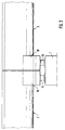
- Fig. 1 - The guideway construction shown in Figures 1 and 2 for an elevated Route guidance - the several meter high support 1 is only hinted at in FIG. 2 shown and completely omitted in Fig. 1 - consists in essentially from a prestressed concrete support pipe 2 and as separate components manufactured guideway slabs 3, these guideway slabs not being of the same length how the prestressed concrete support tube 2 are formed, but from individual plate segments be produced with a correspondingly shorter length. This makes possible, regardless of the production of these track slabs 3 as reinforced concrete slabs or, as shown, as a sheet steel construction, a considerably easier processing of the track slabs.
- the guideway slabs and the actual side member are designed as Longitudinal beam as, at least approximately symmetrical and therefore only slight Unbalancing pipe, which consequently by means of centrifugal concrete production can be manufactured.
- the entire superstructure was the track slab 3 shows, together with the supporting longitudinal tube, which has hitherto been customary had a trapezoidal, enlarged cross-section as a one-piece Component has been made, which makes a meaningful centrifugal concrete production almost impossible made.
- this component had to be independent in every case be handled as a whole by its type of manufacture.
- centrifugal concrete results in a large, continuous interior Cavity 7, which are used to lay cables and supply lines can.
- the prestressed concrete support pipe 2 are in the support area on the pillars 1, generally at the ends at 20 m - 31 m long prestressed concrete support pipes threaded bushings 8 inserted into which anchoring rods 9 can be screwed. These are used for anchoring in Support brackets 10 with the help of which the prestressed concrete support pipe 2 with the track slab 3 is supported on the supports 1.
- the additionally provided, preferably spring-loaded, support feet 11 are known per se and therefore need this Not be described in more detail.
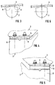
- Track slabs from the prestressed concrete support pipes 2 enable a very simple Elevation of the carriageway in curves, as shown in FIGS. 3 to 5.
- the prestressed concrete support tube rotates about its longitudinal axis is, for example, concreted accordingly to the console 10 is.
- the split design of the guideway slabs is particularly advantageous as individual short plate segments especially for this cant track increase 3 to 5, as this means that the inclination is not constant within one Precast track with 20 m - 31 m length must remain the same, but the Plate segments of approximately 6.20 m each have different inclinations could.
- FIG. 7 and 8 is a schematic view or a section through a Route shown at ground level route guidance.
- one or several guideway slabs 3 with a length of about 6.20 m, which are parallel over two Distance from each other and through a rectangular steel tube 14 with each other Prestressed concrete pipes 2 'screwed to the support directly on the floor foundation 15 is supported.
- Floor foundations 15, which also have anchoring piers 16 can only be provided at a distance that the Length of a prefabricated guideway girder, i.e. in the exemplary embodiment shown about 20 m - 31 m can be provided, while previously supporting the Prefabricated guideway girders with the help of transverse support walls arranged at 3-meter intervals almost ten times as many foundations were required.
- the inner continuous cavity 7 ' which is essentially a rectangular tube trained pre-stressed concrete support pipes 2 ', the space is also particularly suitable between the prestressed concrete rectangular beams to hold cables and supply lines.
- Fig. 9 a section corresponding to Fig. 7 is shown, with a through the wedge plate 17 arranged on the foundation 15 has a path inclination as curve elevation is achieved.
- FIG. 10 shows an enlarged section through a prestressed concrete support pipe 2, in which also arranged in different circular cylindrical planes 18 and 19 Prestressing steels 20 and 21 are also indicated.
- the prestressing steels are in the lower, the support shoulders 4 remote half of the prestressed concrete support pipe 2 packed more densely, possibly also more trained to be in this the lower ones are particularly stressed by tension due to the weight Area to achieve increased reinforcement.
- This asymmetrical distribution the reinforcement can now be combined with an asymmetrical distribution of the Supporting ribs 22 for stiffening the shaped plate 23 within a spun concrete form 24 according to FIG.
Landscapes
- Engineering & Computer Science (AREA)
- Mechanical Engineering (AREA)
- Architecture (AREA)
- Civil Engineering (AREA)
- Structural Engineering (AREA)
- Manufacturing & Machinery (AREA)
- Chemical & Material Sciences (AREA)
- Ceramic Engineering (AREA)
- Manufacturing Of Tubular Articles Or Embedded Moulded Articles (AREA)
- On-Site Construction Work That Accompanies The Preparation And Application Of Concrete (AREA)
- Railway Tracks (AREA)
- Control Of Vehicles With Linear Motors And Vehicles That Are Magnetically Levitated (AREA)
Applications Claiming Priority (3)
| Application Number | Priority Date | Filing Date | Title |
|---|---|---|---|
| DE19919703A DE19919703C2 (de) | 1999-04-30 | 1999-04-30 | Fahrweg für Transrapid |
| DE19919703 | 1999-04-30 | ||
| CA002323977A CA2323977A1 (fr) | 1999-04-30 | 2000-10-19 | Passage pour reseaux de transport terrestre |
Publications (3)
| Publication Number | Publication Date |
|---|---|
| EP1048784A2 true EP1048784A2 (fr) | 2000-11-02 |
| EP1048784A3 EP1048784A3 (fr) | 2000-12-27 |
| EP1048784B1 EP1048784B1 (fr) | 2006-05-24 |
Family
ID=25682175
Family Applications (1)
| Application Number | Title | Priority Date | Filing Date |
|---|---|---|---|
| EP00108482A Expired - Lifetime EP1048784B1 (fr) | 1999-04-30 | 2000-04-19 | Voie pour circulation à lévitation magétique, par exemple TRANSRAPID |
Country Status (3)
| Country | Link |
|---|---|
| EP (1) | EP1048784B1 (fr) |
| CA (1) | CA2323977A1 (fr) |
| DE (1) | DE19919703C2 (fr) |
Cited By (11)
| Publication number | Priority date | Publication date | Assignee | Title |
|---|---|---|---|---|
| KR20020031674A (ko) * | 2000-10-23 | 2002-05-03 | 추후제출 | 경량궤도차용 차도 |
| WO2002075051A3 (fr) * | 2001-02-12 | 2003-01-09 | Lina Lichius | Piste de circulation pour vehicules guides sur piste |
| WO2003023144A1 (fr) * | 2001-09-07 | 2003-03-20 | Shanghai Maglev Transportation Development Co., Ltd | Structure de voie pour transport a grande vitesse |
| WO2003025285A1 (fr) * | 2001-09-21 | 2003-03-27 | Shanghai Maglev Transportation Development Co., Ltd. | Structure de voie pour le transit par voie rapide |
| WO2003102304A1 (fr) | 2002-05-28 | 2003-12-11 | Thyssenkrupp Technologies Ag | Voie de communication pour vehicules a sustentation magnetique |
| WO2004001766A3 (fr) * | 2002-06-25 | 2004-03-18 | Polygro Trading Ag | Systeme de contenants pour le transport et le stockage de materiaux fortement radioactifs |
| WO2004022852A1 (fr) * | 2002-08-14 | 2004-03-18 | Pfleiderer Infrastrukturtechnik Gmbh & Co. Kg | Voie pour trains magnetiques |
| EP1441066A1 (fr) * | 2003-01-17 | 2004-07-28 | Ed. Züblin Ag | Dalle de support, préfabriquée en béton, pour train à lévitation magnétique |
| WO2004063466A1 (fr) * | 2003-01-14 | 2004-07-29 | Schmitt Stumpf Frühauf und Partner Ingenieurgesellschaft im Bauwesen mbH | Piste pour trains a sustentation magnetique, et son procede de production |
| WO2005049921A1 (fr) * | 2003-11-18 | 2005-06-02 | Max Bögl Bauunternehmung GmbH & Co. KG | Procede de positionnement precis d'un support de voie et voie |
| CN107756600A (zh) * | 2017-11-20 | 2018-03-06 | 上海师范大学 | 水泥管片圆弧面自动收水抹平装置 |
Families Citing this family (13)
| Publication number | Priority date | Publication date | Assignee | Title |
|---|---|---|---|---|
| DE10038851A1 (de) | 2000-08-04 | 2002-02-14 | Boegl Max Bauunternehmung Gmbh | Verfahren zum Herstellen einer Verbindungsstelle an einem Fahrweg |
| US6951433B2 (en) | 2000-08-04 | 2005-10-04 | Dieter Reichel | Device for nonpositively fixing a bracket to a supporting base body |
| JP2004509247A (ja) | 2000-09-12 | 2004-03-25 | マクス、ベグル、バウウンテルネームング、ゲゼルシャフト、ミット、ベシュレンクテル、ハフツング、ウント、コンパニー、コマンディトゲゼルシャフト | 走行路支持体 |
| DE10110613B4 (de) * | 2001-03-06 | 2009-06-10 | Otmar Fahrion | Fahrwegsegment für eine Magnetschwebebahn |
| DE10215668A1 (de) * | 2002-04-10 | 2003-10-30 | Zueblin Ag | Fahrweg für Magnetschwebebahn |
| DE10217460C1 (de) * | 2002-04-19 | 2003-12-24 | Pfleiderer Infrastrukturt Gmbh | In Schleuderbeton hergestelltes Spannbetontragrohr, insbesondere für Fahrwege von Magnetschwebebahnen |
| DE20210554U1 (de) * | 2002-07-08 | 2003-11-20 | Wilcken, Alexander von, 80939 München | Kopplungsvorrichtung, insbesondere für einen Fahrweg für eine Magnetschwebebahn, und Fahrweg für eine Magnetschwebebahn |
| DE10239661A1 (de) * | 2002-08-24 | 2004-03-18 | Walter Bau-Ag | Fahrweg in modularer Bauweise, inbesondere für eine Magnetbahn |
| DE10240808A1 (de) * | 2002-08-30 | 2004-03-11 | Walter Bau-Ag | Magnetbahnfahrweg aus Stahlträgern im Verbund mit Fahrwegelementen aus Betonfertigteilen |
| DE102005011838A1 (de) * | 2005-03-15 | 2006-09-21 | Pfleiderer Europoles Gmbh & Co. Kg | Schilderbrücke |
| DE102005057380B4 (de) * | 2005-11-30 | 2009-12-03 | Walter Sobolewski | Röhrenartiger, hohler, fester Fahrwegträger |
| DE102010026586A1 (de) | 2010-07-08 | 2012-01-12 | Roland Lipp | Fahrbahn für eine Magnetschwebebahn |
| DE102010048819A1 (de) | 2010-10-20 | 2012-04-26 | Roland Lipp | Hochgeschwindigkeits-Fernverkehrssystem zum Transport von Personen und/oder Lasten |
Citations (2)
| Publication number | Priority date | Publication date | Assignee | Title |
|---|---|---|---|---|
| DE4115936A1 (de) | 1991-05-16 | 1992-11-19 | Dyckerhoff & Widmann Ag | Aus stahl- oder spannbeton bestehender traeger fuer einen fahrweg fuer magnetschwebefahrzeuge |
| DE29809580U1 (de) | 1998-05-28 | 1998-08-20 | Noell Stahl- und Maschinenbau GmbH, 97080 Würzburg | Fahrwegplatte für die Fahrbahn von Magnetbahnzügen |
Family Cites Families (7)
| Publication number | Priority date | Publication date | Assignee | Title |
|---|---|---|---|---|
| GB561400A (en) * | 1942-11-09 | 1944-05-18 | Paul William Abeles | Improvements in reinforced concrete construction and in methods of, and apparatus for, their production |
| FR1045807A (fr) * | 1951-06-18 | 1953-12-01 | Procédés et appareils de fabrication d'éléments de construction en béton centrifugé et éléments ainsi obtenus | |
| DE1180387B (de) * | 1961-04-21 | 1964-10-29 | Johannes Doernen Fa | Metallene zweigleisige Eisenbahnbruecke |
| JPH01160610A (ja) * | 1987-12-18 | 1989-06-23 | Sumitomo Constr Co Ltd | 多角形中空コンクリート部材の製造用型枠装置 |
| JPH07113435B2 (ja) * | 1989-03-31 | 1995-12-06 | 中川ヒューム管工業株式会社 | 遠心成形コンクリート管 |
| FR2746824A1 (fr) * | 1996-03-27 | 1997-10-03 | Baudin Chateauneuf Sa | Caissons precontraints pour tablier de pont |
| DE19619866C2 (de) * | 1996-05-17 | 2003-10-02 | Boegl Max Bauunternehmung Gmbh | Fahrweg für Magnetbahnzüge |
-
1999
- 1999-04-30 DE DE19919703A patent/DE19919703C2/de not_active Expired - Fee Related
-
2000
- 2000-04-19 EP EP00108482A patent/EP1048784B1/fr not_active Expired - Lifetime
- 2000-10-19 CA CA002323977A patent/CA2323977A1/fr not_active Abandoned
Patent Citations (2)
| Publication number | Priority date | Publication date | Assignee | Title |
|---|---|---|---|---|
| DE4115936A1 (de) | 1991-05-16 | 1992-11-19 | Dyckerhoff & Widmann Ag | Aus stahl- oder spannbeton bestehender traeger fuer einen fahrweg fuer magnetschwebefahrzeuge |
| DE29809580U1 (de) | 1998-05-28 | 1998-08-20 | Noell Stahl- und Maschinenbau GmbH, 97080 Würzburg | Fahrwegplatte für die Fahrbahn von Magnetbahnzügen |
Cited By (14)
| Publication number | Priority date | Publication date | Assignee | Title |
|---|---|---|---|---|
| KR20020031674A (ko) * | 2000-10-23 | 2002-05-03 | 추후제출 | 경량궤도차용 차도 |
| WO2002075051A3 (fr) * | 2001-02-12 | 2003-01-09 | Lina Lichius | Piste de circulation pour vehicules guides sur piste |
| WO2003023144A1 (fr) * | 2001-09-07 | 2003-03-20 | Shanghai Maglev Transportation Development Co., Ltd | Structure de voie pour transport a grande vitesse |
| US7357084B2 (en) | 2001-09-07 | 2008-04-15 | Shanghai Maglev Transportation Development Co., Ltd. | Guideway structure for high-speed track- bound transportation |
| US7182023B2 (en) | 2001-09-21 | 2007-02-27 | Shanghai Maglev Transportation Development Co., Ltd. | Track structure of the rapid track transit |
| WO2003025285A1 (fr) * | 2001-09-21 | 2003-03-27 | Shanghai Maglev Transportation Development Co., Ltd. | Structure de voie pour le transit par voie rapide |
| WO2003102304A1 (fr) | 2002-05-28 | 2003-12-11 | Thyssenkrupp Technologies Ag | Voie de communication pour vehicules a sustentation magnetique |
| WO2004001766A3 (fr) * | 2002-06-25 | 2004-03-18 | Polygro Trading Ag | Systeme de contenants pour le transport et le stockage de materiaux fortement radioactifs |
| WO2004022852A1 (fr) * | 2002-08-14 | 2004-03-18 | Pfleiderer Infrastrukturtechnik Gmbh & Co. Kg | Voie pour trains magnetiques |
| WO2004063466A1 (fr) * | 2003-01-14 | 2004-07-29 | Schmitt Stumpf Frühauf und Partner Ingenieurgesellschaft im Bauwesen mbH | Piste pour trains a sustentation magnetique, et son procede de production |
| EP1441066A1 (fr) * | 2003-01-17 | 2004-07-28 | Ed. Züblin Ag | Dalle de support, préfabriquée en béton, pour train à lévitation magnétique |
| WO2005049921A1 (fr) * | 2003-11-18 | 2005-06-02 | Max Bögl Bauunternehmung GmbH & Co. KG | Procede de positionnement precis d'un support de voie et voie |
| CN107756600A (zh) * | 2017-11-20 | 2018-03-06 | 上海师范大学 | 水泥管片圆弧面自动收水抹平装置 |
| CN107756600B (zh) * | 2017-11-20 | 2024-05-24 | 上海师范大学 | 水泥管片圆弧面自动收水抹平装置 |
Also Published As
| Publication number | Publication date |
|---|---|
| CA2323977A1 (fr) | 2002-04-19 |
| EP1048784B1 (fr) | 2006-05-24 |
| EP1048784A3 (fr) | 2000-12-27 |
| DE19919703C2 (de) | 2001-05-23 |
| DE19919703A1 (de) | 2000-11-16 |
Similar Documents
| Publication | Publication Date | Title |
|---|---|---|
| DE19919703C2 (de) | Fahrweg für Transrapid | |
| EP2088244B1 (fr) | Pont en béton armé ou pont de construction composite et methode pour sa fabrication | |
| DE2233518A1 (de) | Brueckenkonstruktion | |
| EP2623670A2 (fr) | Voie sans ballast pour véhicules ferroviaires | |
| EP3303707A1 (fr) | Procédé de fabrication d'une dalle de tablier pour un pont | |
| EP0556609B1 (fr) | Quai ferroviaire | |
| DE2247609B1 (de) | Verfahren zum herstellen eines brueckenbauwerks aus spannbeton im abschnittsweisen freien vorbau | |
| DE1286529B (de) | Bruecke od. dgl. mit Stuetzen und von diesen getragenen UEberbauabschnitten | |
| DE2338926A1 (de) | Tragwerk einer schnellbahn | |
| DE102011102987A1 (de) | Das Taktschiebeverfahren mit Stützweitenreduzierung für Strassen- und Bahnbrücken mit Plattenbalkenquerschnitt | |
| EP2166149B2 (fr) | Unité de pièce de structure de voie ferrée | |
| DE2216484A1 (de) | Verfahren zum herstellen einer fahrbahn aus stahl- oder spannbeton | |
| DE19831984C2 (de) | Bauteil mit externen Spanngliedern | |
| DE102017131351A1 (de) | Trogförmiger Überbau für eine Brücke, Brücke, Fertigteil für eine Trogwange einer Brücke sowie Verfahren zur Herstellung einer Brücke | |
| AT380502B (de) | Verfahren und vorrichtung zum verbreitern von fahrbahnplatten, brueckenfahrbahnen od.dgl. | |
| DE2747049C2 (fr) | ||
| DE3203980C2 (de) | Unterführungsbauwerk sowie Verfahren zu seiner Herstellung | |
| AT388004B (de) | Abstuetzeinrichtung fuer gleise | |
| EP0056422A1 (fr) | Procédé et faux-oeuvre pour la construction de ponts en béton armé | |
| DE10221626A1 (de) | Fahrweg für eine Magnetschwebebahn und Verfahren zur Herstellung eines Fahrwegs für eine Magnetschwebebahn | |
| AT344780B (de) | Spannbeton-fahrbahnplatte | |
| DE10305576A1 (de) | Fahrweg für ein spurgebundenes Fahrzeug, insbesondere eine Magnetschwebebahn | |
| DE19944783A1 (de) | Feste-Fahrbahn-System | |
| AT412734B (de) | Verkehrsfläche | |
| DE1220879B (de) | Unterfuehrungsbauwerk und Verfahren zu seinem nachtraeglichen Einbau |
Legal Events
| Date | Code | Title | Description |
|---|---|---|---|
| PUAI | Public reference made under article 153(3) epc to a published international application that has entered the european phase |
Free format text: ORIGINAL CODE: 0009012 |
|
| AK | Designated contracting states |
Kind code of ref document: A2 Designated state(s): AT BE CH CY DE DK ES FI FR GB GR IE IT LI LU MC NL PT SE |
|
| AX | Request for extension of the european patent |
Free format text: AL;LT;LV;MK;RO;SI |
|
| PUAL | Search report despatched |
Free format text: ORIGINAL CODE: 0009013 |
|
| RIC1 | Information provided on ipc code assigned before grant |
Free format text: 7E 01B 25/00 A, 7E 01D 2/00 B, 7B 28B 21/30 B |
|
| AK | Designated contracting states |
Kind code of ref document: A3 Designated state(s): AT BE CH CY DE DK ES FI FR GB GR IE IT LI LU MC NL PT SE |
|
| AX | Request for extension of the european patent |
Free format text: AL;LT;LV;MK;RO;SI |
|
| 17P | Request for examination filed |
Effective date: 20010606 |
|
| AKX | Designation fees paid |
Free format text: AT BE CH CY DE DK ES FI FR GB GR IE IT LI LU MC NL PT SE |
|
| AXX | Extension fees paid |
Free format text: AL PAYMENT 20010606;LT PAYMENT 20010606;LV PAYMENT 20010606;MK PAYMENT 20010606;RO PAYMENT 20010606;SI PAYMENT 20010606 |
|
| 17Q | First examination report despatched |
Effective date: 20031114 |
|
| GRAP | Despatch of communication of intention to grant a patent |
Free format text: ORIGINAL CODE: EPIDOSNIGR1 |
|
| RTI1 | Title (correction) |
Free format text: TRACK FOR MAGNETIC LEVITATION TRAFFIC, FOR EXAMPLE TRANSRAPID |
|
| GRAS | Grant fee paid |
Free format text: ORIGINAL CODE: EPIDOSNIGR3 |
|
| GRAA | (expected) grant |
Free format text: ORIGINAL CODE: 0009210 |
|
| AK | Designated contracting states |
Kind code of ref document: B1 Designated state(s): AT BE CH CY DE DK ES FI FR GB GR IE IT LI LU MC NL PT SE |
|
| AX | Request for extension of the european patent |
Extension state: AL LT LV MK RO SI |
|
| PG25 | Lapsed in a contracting state [announced via postgrant information from national office to epo] |
Ref country code: IT Free format text: LAPSE BECAUSE OF FAILURE TO SUBMIT A TRANSLATION OF THE DESCRIPTION OR TO PAY THE FEE WITHIN THE PRESCRIBED TIME-LIMIT;WARNING: LAPSES OF ITALIAN PATENTS WITH EFFECTIVE DATE BEFORE 2007 MAY HAVE OCCURRED AT ANY TIME BEFORE 2007. THE CORRECT EFFECTIVE DATE MAY BE DIFFERENT FROM THE ONE RECORDED. Effective date: 20060524 Ref country code: FI Free format text: LAPSE BECAUSE OF FAILURE TO SUBMIT A TRANSLATION OF THE DESCRIPTION OR TO PAY THE FEE WITHIN THE PRESCRIBED TIME-LIMIT Effective date: 20060524 Ref country code: IE Free format text: LAPSE BECAUSE OF FAILURE TO SUBMIT A TRANSLATION OF THE DESCRIPTION OR TO PAY THE FEE WITHIN THE PRESCRIBED TIME-LIMIT Effective date: 20060524 |
|
| REG | Reference to a national code |
Ref country code: GB Ref legal event code: FG4D Free format text: NOT ENGLISH |
|
| REG | Reference to a national code |
Ref country code: CH Ref legal event code: EP |
|
| REG | Reference to a national code |
Ref country code: IE Ref legal event code: FG4D Free format text: LANGUAGE OF EP DOCUMENT: GERMAN |
|
| REF | Corresponds to: |
Ref document number: 50012800 Country of ref document: DE Date of ref document: 20060629 Kind code of ref document: P |
|
| PG25 | Lapsed in a contracting state [announced via postgrant information from national office to epo] |
Ref country code: SE Free format text: LAPSE BECAUSE OF FAILURE TO SUBMIT A TRANSLATION OF THE DESCRIPTION OR TO PAY THE FEE WITHIN THE PRESCRIBED TIME-LIMIT Effective date: 20060824 Ref country code: DK Free format text: LAPSE BECAUSE OF FAILURE TO SUBMIT A TRANSLATION OF THE DESCRIPTION OR TO PAY THE FEE WITHIN THE PRESCRIBED TIME-LIMIT Effective date: 20060824 |
|
| PG25 | Lapsed in a contracting state [announced via postgrant information from national office to epo] |
Ref country code: ES Free format text: LAPSE BECAUSE OF FAILURE TO SUBMIT A TRANSLATION OF THE DESCRIPTION OR TO PAY THE FEE WITHIN THE PRESCRIBED TIME-LIMIT Effective date: 20060904 |
|
| GBT | Gb: translation of ep patent filed (gb section 77(6)(a)/1977) |
Effective date: 20060905 |
|
| PG25 | Lapsed in a contracting state [announced via postgrant information from national office to epo] |
Ref country code: PT Free format text: LAPSE BECAUSE OF FAILURE TO SUBMIT A TRANSLATION OF THE DESCRIPTION OR TO PAY THE FEE WITHIN THE PRESCRIBED TIME-LIMIT Effective date: 20061024 |
|
| LTIE | Lt: invalidation of european patent or patent extension |
Effective date: 20060524 |
|
| REG | Reference to a national code |
Ref country code: IE Ref legal event code: FD4D |
|
| PLBE | No opposition filed within time limit |
Free format text: ORIGINAL CODE: 0009261 |
|
| STAA | Information on the status of an ep patent application or granted ep patent |
Free format text: STATUS: NO OPPOSITION FILED WITHIN TIME LIMIT |
|
| NLS | Nl: assignments of ep-patents |
Owner name: RAIL.ONE GMBH Effective date: 20070131 |
|
| 26N | No opposition filed |
Effective date: 20070227 |
|
| EN | Fr: translation not filed | ||
| REG | Reference to a national code |
Ref country code: GB Ref legal event code: 732E |
|
| REG | Reference to a national code |
Ref country code: CH Ref legal event code: PL |
|
| BERE | Be: lapsed |
Owner name: PFLEIDERER INFRASTRUKTURTECHNIK G.M.B.H. & CO. KG Effective date: 20070430 |
|
| PG25 | Lapsed in a contracting state [announced via postgrant information from national office to epo] |
Ref country code: CH Free format text: LAPSE BECAUSE OF NON-PAYMENT OF DUE FEES Effective date: 20070430 Ref country code: LI Free format text: LAPSE BECAUSE OF NON-PAYMENT OF DUE FEES Effective date: 20070430 |
|
| PG25 | Lapsed in a contracting state [announced via postgrant information from national office to epo] |
Ref country code: BE Free format text: LAPSE BECAUSE OF NON-PAYMENT OF DUE FEES Effective date: 20070430 |
|
| PG25 | Lapsed in a contracting state [announced via postgrant information from national office to epo] |
Ref country code: GR Free format text: LAPSE BECAUSE OF FAILURE TO SUBMIT A TRANSLATION OF THE DESCRIPTION OR TO PAY THE FEE WITHIN THE PRESCRIBED TIME-LIMIT Effective date: 20060825 Ref country code: FR Free format text: LAPSE BECAUSE OF FAILURE TO SUBMIT A TRANSLATION OF THE DESCRIPTION OR TO PAY THE FEE WITHIN THE PRESCRIBED TIME-LIMIT Effective date: 20070309 |
|
| PG25 | Lapsed in a contracting state [announced via postgrant information from national office to epo] |
Ref country code: AT Free format text: LAPSE BECAUSE OF NON-PAYMENT OF DUE FEES Effective date: 20070419 |
|
| PG25 | Lapsed in a contracting state [announced via postgrant information from national office to epo] |
Ref country code: FR Free format text: LAPSE BECAUSE OF FAILURE TO SUBMIT A TRANSLATION OF THE DESCRIPTION OR TO PAY THE FEE WITHIN THE PRESCRIBED TIME-LIMIT Effective date: 20060524 |
|
| PG25 | Lapsed in a contracting state [announced via postgrant information from national office to epo] |
Ref country code: MC Free format text: LAPSE BECAUSE OF NON-PAYMENT OF DUE FEES Effective date: 20070430 |
|
| PG25 | Lapsed in a contracting state [announced via postgrant information from national office to epo] |
Ref country code: LU Free format text: LAPSE BECAUSE OF NON-PAYMENT OF DUE FEES Effective date: 20070419 Ref country code: CY Free format text: LAPSE BECAUSE OF FAILURE TO SUBMIT A TRANSLATION OF THE DESCRIPTION OR TO PAY THE FEE WITHIN THE PRESCRIBED TIME-LIMIT Effective date: 20060524 |
|
| PGFP | Annual fee paid to national office [announced via postgrant information from national office to epo] |
Ref country code: DE Payment date: 20100427 Year of fee payment: 11 Ref country code: NL Payment date: 20100421 Year of fee payment: 11 |
|
| PGFP | Annual fee paid to national office [announced via postgrant information from national office to epo] |
Ref country code: GB Payment date: 20100401 Year of fee payment: 11 |
|
| REG | Reference to a national code |
Ref country code: DE Ref legal event code: R119 Ref document number: 50012800 Country of ref document: DE |
|
| REG | Reference to a national code |
Ref country code: DE Ref legal event code: R119 Ref document number: 50012800 Country of ref document: DE |
|
| REG | Reference to a national code |
Ref country code: NL Ref legal event code: V1 Effective date: 20111101 |
|
| GBPC | Gb: european patent ceased through non-payment of renewal fee |
Effective date: 20110419 |
|
| PG25 | Lapsed in a contracting state [announced via postgrant information from national office to epo] |
Ref country code: NL Free format text: LAPSE BECAUSE OF NON-PAYMENT OF DUE FEES Effective date: 20111101 |
|
| PG25 | Lapsed in a contracting state [announced via postgrant information from national office to epo] |
Ref country code: GB Free format text: LAPSE BECAUSE OF NON-PAYMENT OF DUE FEES Effective date: 20110419 |
|
| PG25 | Lapsed in a contracting state [announced via postgrant information from national office to epo] |
Ref country code: DE Free format text: LAPSE BECAUSE OF NON-PAYMENT OF DUE FEES Effective date: 20111031 |