EP1048839A1 - Wärme tauscher aus Plastik und Stahl zum Einbau in einem Stromkreis des Lufteinlasses einer Brennkraftmaschine - Google Patents
Wärme tauscher aus Plastik und Stahl zum Einbau in einem Stromkreis des Lufteinlasses einer Brennkraftmaschine Download PDFInfo
- Publication number
- EP1048839A1 EP1048839A1 EP00401061A EP00401061A EP1048839A1 EP 1048839 A1 EP1048839 A1 EP 1048839A1 EP 00401061 A EP00401061 A EP 00401061A EP 00401061 A EP00401061 A EP 00401061A EP 1048839 A1 EP1048839 A1 EP 1048839A1
- Authority
- EP
- European Patent Office
- Prior art keywords
- heat exchanger
- chamber
- opening
- intake
- partition
- Prior art date
- Legal status (The legal status is an assumption and is not a legal conclusion. Google has not performed a legal analysis and makes no representation as to the accuracy of the status listed.)
- Granted
Links
Images


Classifications
-
- F—MECHANICAL ENGINEERING; LIGHTING; HEATING; WEAPONS; BLASTING
- F28—HEAT EXCHANGE IN GENERAL
- F28F—DETAILS OF HEAT-EXCHANGE AND HEAT-TRANSFER APPARATUS, OF GENERAL APPLICATION
- F28F9/00—Casings; Header boxes; Auxiliary supports for elements; Auxiliary members within casings
- F28F9/02—Header boxes; End plates
- F28F9/0219—Arrangements for sealing end plates into casing or header box; Header box sub-elements
-
- F—MECHANICAL ENGINEERING; LIGHTING; HEATING; WEAPONS; BLASTING
- F02—COMBUSTION ENGINES; HOT-GAS OR COMBUSTION-PRODUCT ENGINE PLANTS
- F02M—SUPPLYING COMBUSTION ENGINES IN GENERAL WITH COMBUSTIBLE MIXTURES OR CONSTITUENTS THEREOF
- F02M26/00—Engine-pertinent apparatus for adding exhaust gases to combustion-air, main fuel or fuel-air mixture, e.g. by exhaust gas recirculation [EGR] systems
- F02M26/11—Manufacture or assembly of EGR systems; Materials or coatings specially adapted for EGR systems
-
- F—MECHANICAL ENGINEERING; LIGHTING; HEATING; WEAPONS; BLASTING
- F02—COMBUSTION ENGINES; HOT-GAS OR COMBUSTION-PRODUCT ENGINE PLANTS
- F02M—SUPPLYING COMBUSTION ENGINES IN GENERAL WITH COMBUSTIBLE MIXTURES OR CONSTITUENTS THEREOF
- F02M26/00—Engine-pertinent apparatus for adding exhaust gases to combustion-air, main fuel or fuel-air mixture, e.g. by exhaust gas recirculation [EGR] systems
- F02M26/13—Arrangement or layout of EGR passages, e.g. in relation to specific engine parts or for incorporation of accessories
- F02M26/22—Arrangement or layout of EGR passages, e.g. in relation to specific engine parts or for incorporation of accessories with coolers in the recirculation passage
- F02M26/29—Constructional details of the coolers, e.g. pipes, plates, ribs, insulation or materials
- F02M26/30—Connections of coolers to other devices, e.g. to valves, heaters, compressors or filters; Coolers characterised by their location on the engine
-
- F—MECHANICAL ENGINEERING; LIGHTING; HEATING; WEAPONS; BLASTING
- F02—COMBUSTION ENGINES; HOT-GAS OR COMBUSTION-PRODUCT ENGINE PLANTS
- F02M—SUPPLYING COMBUSTION ENGINES IN GENERAL WITH COMBUSTIBLE MIXTURES OR CONSTITUENTS THEREOF
- F02M26/00—Engine-pertinent apparatus for adding exhaust gases to combustion-air, main fuel or fuel-air mixture, e.g. by exhaust gas recirculation [EGR] systems
- F02M26/13—Arrangement or layout of EGR passages, e.g. in relation to specific engine parts or for incorporation of accessories
- F02M26/22—Arrangement or layout of EGR passages, e.g. in relation to specific engine parts or for incorporation of accessories with coolers in the recirculation passage
- F02M26/29—Constructional details of the coolers, e.g. pipes, plates, ribs, insulation or materials
- F02M26/32—Liquid-cooled heat exchangers
-
- F—MECHANICAL ENGINEERING; LIGHTING; HEATING; WEAPONS; BLASTING
- F28—HEAT EXCHANGE IN GENERAL
- F28D—HEAT-EXCHANGE APPARATUS, NOT PROVIDED FOR IN ANOTHER SUBCLASS, IN WHICH THE HEAT-EXCHANGE MEDIA DO NOT COME INTO DIRECT CONTACT
- F28D7/00—Heat-exchange apparatus having stationary tubular conduit assemblies for both heat-exchange media, the media being in contact with different sides of a conduit wall
- F28D7/16—Heat-exchange apparatus having stationary tubular conduit assemblies for both heat-exchange media, the media being in contact with different sides of a conduit wall the conduits being arranged in parallel spaced relation
-
- F—MECHANICAL ENGINEERING; LIGHTING; HEATING; WEAPONS; BLASTING
- F28—HEAT EXCHANGE IN GENERAL
- F28D—HEAT-EXCHANGE APPARATUS, NOT PROVIDED FOR IN ANOTHER SUBCLASS, IN WHICH THE HEAT-EXCHANGE MEDIA DO NOT COME INTO DIRECT CONTACT
- F28D9/00—Heat-exchange apparatus having stationary plate-like or laminated conduit assemblies for both heat-exchange media, the media being in contact with different sides of a conduit wall
-
- F—MECHANICAL ENGINEERING; LIGHTING; HEATING; WEAPONS; BLASTING
- F28—HEAT EXCHANGE IN GENERAL
- F28F—DETAILS OF HEAT-EXCHANGE AND HEAT-TRANSFER APPARATUS, OF GENERAL APPLICATION
- F28F21/00—Constructions of heat-exchange apparatus characterised by the selection of particular materials
- F28F21/06—Constructions of heat-exchange apparatus characterised by the selection of particular materials of plastics material
- F28F21/067—Details
-
- F—MECHANICAL ENGINEERING; LIGHTING; HEATING; WEAPONS; BLASTING
- F28—HEAT EXCHANGE IN GENERAL
- F28D—HEAT-EXCHANGE APPARATUS, NOT PROVIDED FOR IN ANOTHER SUBCLASS, IN WHICH THE HEAT-EXCHANGE MEDIA DO NOT COME INTO DIRECT CONTACT
- F28D21/00—Heat-exchange apparatus not covered by any of the groups F28D1/00 - F28D20/00
- F28D21/0001—Recuperative heat exchangers
- F28D21/0003—Recuperative heat exchangers the heat being recuperated from exhaust gases
-
- F—MECHANICAL ENGINEERING; LIGHTING; HEATING; WEAPONS; BLASTING
- F28—HEAT EXCHANGE IN GENERAL
- F28F—DETAILS OF HEAT-EXCHANGE AND HEAT-TRANSFER APPARATUS, OF GENERAL APPLICATION
- F28F2265/00—Safety or protection arrangements; Arrangements for preventing malfunction
- F28F2265/26—Safety or protection arrangements; Arrangements for preventing malfunction for allowing differential expansion between elements
-
- F—MECHANICAL ENGINEERING; LIGHTING; HEATING; WEAPONS; BLASTING
- F28—HEAT EXCHANGE IN GENERAL
- F28F—DETAILS OF HEAT-EXCHANGE AND HEAT-TRANSFER APPARATUS, OF GENERAL APPLICATION
- F28F2275/00—Fastening; Joining
- F28F2275/08—Fastening; Joining by clamping or clipping
- F28F2275/085—Fastening; Joining by clamping or clipping with snap connection
-
- F—MECHANICAL ENGINEERING; LIGHTING; HEATING; WEAPONS; BLASTING
- F28—HEAT EXCHANGE IN GENERAL
- F28F—DETAILS OF HEAT-EXCHANGE AND HEAT-TRANSFER APPARATUS, OF GENERAL APPLICATION
- F28F9/00—Casings; Header boxes; Auxiliary supports for elements; Auxiliary members within casings
- F28F9/007—Auxiliary supports for elements
- F28F9/013—Auxiliary supports for elements for tubes or tube-assemblies
-
- Y—GENERAL TAGGING OF NEW TECHNOLOGICAL DEVELOPMENTS; GENERAL TAGGING OF CROSS-SECTIONAL TECHNOLOGIES SPANNING OVER SEVERAL SECTIONS OF THE IPC; TECHNICAL SUBJECTS COVERED BY FORMER USPC CROSS-REFERENCE ART COLLECTIONS [XRACs] AND DIGESTS
- Y02—TECHNOLOGIES OR APPLICATIONS FOR MITIGATION OR ADAPTATION AGAINST CLIMATE CHANGE
- Y02T—CLIMATE CHANGE MITIGATION TECHNOLOGIES RELATED TO TRANSPORTATION
- Y02T10/00—Road transport of goods or passengers
- Y02T10/10—Internal combustion engine [ICE] based vehicles
- Y02T10/12—Improving ICE efficiencies
Definitions
- the present invention relates to elements of the air intake circuit for a combustion engine internal arranged in communication with the engine head to supply air to the different cylinders of the engine, e.g. intake manifold, filter or tube of connection between the filter and the distributor.
- This kind of elements of the intake circuit in particular a distributor, generally comprises a body, in particular of material plastic, defining an air intake chamber, having an inlet for air and an outlet for communication with the engine head.
- the present invention also relates to heat exchangers intended to be arranged in the air intake circuit of a combustion engine.
- the aim is to overcome these disadvantages thanks to an element of the intake circuit for an internal combustion engine, in particular a distributor intake system, which allows exhaust gas recycling which is nevertheless easy to manufacture, both in terms of cost than labor, by reducing the number of connections by welding to be carried out on the heat exchanger, and which provides an element of the intake circuit for a particularly efficient internal combustion engine which concerns the recycling of exhaust gases without harming provided its integrity, in particular in the case of plastic intake manifolds, which have tendency to deteriorate by melting plastic under the effect of high exhaust gas temperatures.
- a locking device in particular by latching, to fix the assembly to the circuit element intake, in its operating position in the auxiliary room.
- the second metal element is also interposed between the assembly forming the hot part located in the second end compartment and the chamber wall auxiliary or grille.
- the first metallic element is directly in contact with the coldest part of the coolant, which keeps it at the lowest possible temperature by conduction on all its part, which allows to thermally separate from efficiently the hottest part of the assembly of the plastic partition.
- the second metallic element is plumb with the fourth opening, which allows also to cool in the same way as the first metal element through the third opening, the second metallic element by conduction as a whole, which ensures good thermal separation between the hot part of the outlet side heat exchanger and the partition defining the auxiliary chamber.
- the auxiliary chamber is cylindrical
- the heat exchanger is a cylindrical heat exchanger consisting of first funnel and a second funnel between which extends a bundle of tubes
- the two elements metallic are in the form of a cylindrical bell consisting of two rings arranged side by side with spokes and connected to each other by a step or rim, the ring with the smallest radius just below the third opening, while the ring of larger diameter fits snugly to the cylindrical-circular partition of the auxiliary chamber.
- a seal in particular an annular seal in the case of a cylindrical heat exchanger.
- a seal is also provided between the second metal element and the room partition auxiliary.
- the outlet of the hot part of the heat exchanger heat is formed by a bent tube whose distal end coincides with the second opening of the chamber auxiliary.
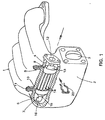
- FIG 1 there is shown a distributor of admission, which is intended to be in communication with the head of an engine to transmit air intake for the engine combustion cycle.
- This intake manifold in Figure 1 consists of a hollow body 1 defining an inlet chamber 2.
- the chamber 2 formed in the body 1 has an opening 3 in communication with the throttle body, through which fresh intake air.
- Bedroom 2 also has four openings each in communication with the head of the engine and through which the intake air comes out after been distributed in the intake manifold.
- the body 1 hollow present in the vicinity of the four openings (which are not shown in the figure because hidden by the perspective) the shape of four conduits arranged one at a side of the others that allow air distribution intake through the opening 3.
- the auxiliary bedroom 5 includes a first opening 6 in communication with outside, a second opening 7 making it possible to make communicate auxiliary room 5 with room 2 intake, a third opening 8 communicating with a cooling fluid supply channel 9, in connection with a cooling system, for example the engine.
- Chamber 5 further includes a fourth opening 10 in communication with a fluid outlet channel 11 of cooling to send it back to the system engine coolant supply.
- the auxiliary chamber 5 is of substantially cylindrical-circular shape. It is the grille (i.e.
- This heat exchanger is intended to cool gases exhaust to be able to recycle them in the room intake manifold. These gases exhaust will flow in what's called the hot part of the heat exchanger being cooled by the coolant arriving via channel 9 coolant inlet and coming out through the coolant outlet channel 11. It is by opening 7 that the cooled exhaust gases are going ability to enter intake room 1 for return to the engine after being distributed among different ducts of the intake manifold.
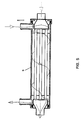
- the hot part of the heat exchanger is consisting of a set of stainless steel parts, which are assembled by strong soldering. They include a inlet flange (any other connection system that can also be considered) for the gas supply exhaust, this flange 12 being connected to a funnel 13 which distributes the exhaust gases over the whole tubes 14 of a bundle of tubes.
- the set of tubes 14 is connected on the other side to another funnel 15 which is intended to collect all the exhaust gases from different tubes 14 for conducting these exhaust gases through the opening 7 via a bent conduit 16.
- the coolant after entering through the opening 8 circulates around the tubes 14 to cool the exhaust gas that is inside these tubes 14 and circulating there, then the coolant a slightly heated, comes out through the opening 10 through the channel 11 in direction of a fluid supply system of cooling, especially in cooling water, with a view to of its recycling to return via channel 9 of water supply.
- This bell 17 is constituted of two annular rings 18 and 19 connected by a rung 20 annular, one of the annular rings 19 being of diameter lower than the other annular ring 18.
- the diameter of the annular ring 18 of bell 17 is chosen so as to match the diameter of the cross section circular of the auxiliary chamber 5, so that the connection between the wall 6 of the auxiliary chamber 5 and the bell 17, via its annular ring 18 of larger diameter, be sealed, when the introduction of the hot part of the heat exchanger in the auxiliary chamber 5.
- annular ring 19 of the bell 17 applies tightly to the funnel 13 on the large diameter thereof.
- the ring 19 of the bell 17 is maintained at a coldest possible cold temperature and by conduction, the bell 17 which is made of metallic material especially in stainless steel, is maintained at a temperature cold enough not to melt the partition 6 in plastic of the auxiliary chamber 5, with which it is in contact at the level of the larger annular ring 18 diameter.
- the bell 17 is arranged on the funnel 13 of so as not to allow the exit of the fluid from cooling through opening 6 of chamber 5 auxiliary.
- the length (1) of the axial extent of the ring 19 ring of bell 17 is to be determined according to characteristics of the exchanger.
- a 21 O-ring seal helps strengthen sealing of the connection between the plastic partition 6 and the bell 17 made of metallic material.
- the same layout a bell is made around the funnel 15 on the side of the cooled part of the exhaust gases.
- the gas inlet temperature is 480 ° and outlet 400 °
- the water is 80 ° in inlet and 81 ° in outlet.
- a heat exchanger formed is shown here a grille which is constituted by the partition 6 of the auxiliary chamber 5 and by a hot part which is cylindrical shape.
- a grille which is constituted by the partition 6 of the auxiliary chamber 5 and by a hot part which is cylindrical shape.
- any other form is suitable also for example a square shape, a shape rectangular, or even oval, as in the case of an exchanger plate heat rather than tube bundle.
- a clip 22 can be provided to come snap onto the fitting of the hot part of heat exchanger and thus prevent removal not the hot part of the heat exchanger.
- the interest of the device as presented is the fact that we can manufacture separately on the one hand the intake distributor part which forms also the grille of the heat exchanger and which is plastic and on the other hand the metal part or stainless steel and which is the hot part of the heat exchanger heat.
- This hot part has parts cylindrical or other simple to assemble by brazing, the number of these solders being limited compared to exchangers known and used today, thereby reducing risk of leaks and touch-ups during manufacturing.
- O-rings allow threading the whole along the axis in the plastic and come lock using the steel wire clip for example very quickly. This can be done at the plastic maker.
- the rigid non-assembly of the two parts cold and hot also allows the elements to expand during temperature variations without causing damage to the system as a whole.
- plastic cylinder also allows to integrate the external grille of the cold part which is plastic in another part of the motor made of the same material, for example in our case here, the intake dispatcher.
- plastic engine parts can be chosen to serve as a plastic radiator grille heat to cool the front exhaust to recycle them in the intake chamber.
- a independent plastic part can be produced for its fixing in the exhaust gas circuit.
- Figure 4 is a perspective view of another embodiment of a following intake manifold the invention. Identical elements or functions identical to those of the embodiment of FIG. 1 are designated by the same reference numerals.
- the heat exchanger is, in this mode of realization, a plate exchanger.
- Coolant circulates in this auxiliary room 25 when entering, cold, via an entry 27 coolant and coming out somewhat warmed up in contact with the exhaust gas, through an outlet 28.
- the transverse plates are arranged one above the other. Gas exhaust penetrate after passing between the plates transverse, in chamber 2 through an opening in the last plate of the heat exchanger, last plate which is constituted by a part 29 in the form of plate of the outer wall of the body 1 made of plastic. As the gases have been sufficiently cooled previously by the network of metal plates, exhaust gases do not damage this plate-shaped part 29 of the plastic outer wall of the body 1.
- the rest of the partition, which constitutes the chamber 25, is therefore metallic.
- the last metal plate adjacent to the plastic plate 29 therefore constitutes, with the walls metal of the chamber 25 the metallic elements dividing the auxiliary chamber 25 into a first compartment end, a central compartment and a second end compartment.
- the first end compartment is made up by the space between the last metal plate and part 29 in the form of a plastic plate of the body 1 hollow.
- the second end compartment is made up by the space formed between entry 12 and the first plate plate heat exchanger and compartment central consists of the space between the first plate metallic and the last, which also plays the role of metallic elements.
- FIG 5 is a side view of a heat exchanger heat according to the invention. This one is intended to be arranged in the air intake circuit of a internal combustion, in particular by being integrated therein element of the intake circuit, for example as described for the intake manifold in Figures 1 to 3 or 4.
- the heat exchanger consists of a grille 5 of cylindrical shape. This grille 5 corresponds to the auxiliary chamber 5 of the intake manifold of the Figures 1 to 3. The rest of the parts of the heat exchanger is identical to what is depicted in Figure 2.
- hot gas flows in a straight line, passing through the tubes
- cold gas via channels 9 and 11 and passing around the tubes
Landscapes
- Engineering & Computer Science (AREA)
- Mechanical Engineering (AREA)
- General Engineering & Computer Science (AREA)
- Physics & Mathematics (AREA)
- Thermal Sciences (AREA)
- Chemical & Material Sciences (AREA)
- Combustion & Propulsion (AREA)
- Manufacturing & Machinery (AREA)
- Heat-Exchange Devices With Radiators And Conduit Assemblies (AREA)
- Exhaust Silencers (AREA)
Applications Claiming Priority (2)
| Application Number | Priority Date | Filing Date | Title |
|---|---|---|---|
| FR9905453 | 1999-04-29 | ||
| FR9905453A FR2792968B1 (fr) | 1999-04-29 | 1999-04-29 | Echangeur thermique en plastique et acier destine a etre dispose dans un circuit d'admission d'air d'un moteur, notamment dans un repartiteur comportant deux chambres et element du circuit d'admission d'air d'un moteur |
Publications (2)
| Publication Number | Publication Date |
|---|---|
| EP1048839A1 true EP1048839A1 (de) | 2000-11-02 |
| EP1048839B1 EP1048839B1 (de) | 2003-09-03 |
Family
ID=9545030
Family Applications (1)
| Application Number | Title | Priority Date | Filing Date |
|---|---|---|---|
| EP00401061A Expired - Lifetime EP1048839B1 (de) | 1999-04-29 | 2000-04-17 | Wärme tauscher aus Plastik und Stahl zum Einbau in einem Stromkreis des Lufteinlasses einer Brennkraftmaschine |
Country Status (6)
| Country | Link |
|---|---|
| US (1) | US6311678B1 (de) |
| EP (1) | EP1048839B1 (de) |
| AT (1) | ATE248986T1 (de) |
| DE (1) | DE60004919T2 (de) |
| ES (1) | ES2206156T3 (de) |
| FR (1) | FR2792968B1 (de) |
Cited By (13)
| Publication number | Priority date | Publication date | Assignee | Title |
|---|---|---|---|---|
| EP1059435A3 (de) * | 1999-06-11 | 2001-06-20 | Pierburg Aktiengesellschaft | Luftansaugkanalanordnung für eine Brennkraftmaschine |
| FR2827949A1 (fr) * | 2001-07-26 | 2003-01-31 | Denso Corp | Echangeur thermique des gaz d'echappement |
| DE10153033A1 (de) * | 2001-10-26 | 2003-05-08 | Bayerische Motoren Werke Ag | Abgas-Rückführ-Wärmetauscher für eine flüssigkeitsgekühlte Brennkraftmaschine |
| EP1479902A1 (de) * | 2003-05-14 | 2004-11-24 | Pierburg GmbH | Luftansaugkanalsystem für eine Verbrennungskraftmaschine |
| EP1770271A1 (de) * | 2005-09-28 | 2007-04-04 | Kubota Corporation | Brennkraftmaschine mit mehreren Zylindern und EGR-Kühler |
| WO2008003486A1 (de) * | 2006-07-06 | 2008-01-10 | Behr Gmbh & Co. Kg | Abgaskühler, insbesondere für ein kraftfahrzeug |
| EP1900931A1 (de) * | 2006-09-05 | 2008-03-19 | Honeywell International Inc. | Wärmeausdehnungsfunktion für einen Abgaskühler |
| WO2008092677A1 (de) * | 2007-01-31 | 2008-08-07 | Behr Gmbh & Co. Kg | Wärmetauscher |
| EP2055921A1 (de) * | 2007-10-31 | 2009-05-06 | Behr GmbH & Co. KG | Ansaugluft-Einlassmodul, Ansaugluft-Einlasssystem, Ansaugluft-Einlasstrakt, Abgasrückführsystem, Verbrennungsmotor |
| EP1895258A3 (de) * | 2006-08-31 | 2010-11-24 | Mahle International GmbH | Wärmeübertragereinrichtung |
| EP2722516A1 (de) * | 2012-10-19 | 2014-04-23 | Systèmes Moteurs (Société par Actions Simplifiée) | Ansaugkrümmer mit integriertem Wärmetauscher und Verfahren zu seiner Herstellung |
| EP2227667B1 (de) | 2007-11-27 | 2016-02-10 | Valeo Termico S.A. | Wärmetauscher für gase, insbesondere für das abgas aus einem motor |
| FR3062173A1 (fr) * | 2017-01-24 | 2018-07-27 | Renault S.A.S | Moteur comprenant une ligne d'alimentation en gaz d'admission pourvu d'au moins un echangeur thermique |
Families Citing this family (36)
| Publication number | Priority date | Publication date | Assignee | Title |
|---|---|---|---|---|
| JP2001059458A (ja) * | 1999-06-16 | 2001-03-06 | Aichi Mach Ind Co Ltd | 内燃機関用吸気マニホールド |
| JP3991786B2 (ja) * | 2002-06-28 | 2007-10-17 | 株式会社デンソー | 排気熱交換装置 |
| US7171956B2 (en) * | 2002-08-28 | 2007-02-06 | T. Rad Co., Ltd. | EGR cooler |
| DE10247837A1 (de) * | 2002-10-14 | 2004-04-22 | Behr Gmbh & Co. | Wärmeübertrager |
| US7107765B2 (en) * | 2003-05-09 | 2006-09-19 | Fults Steven P | System for improving motor vehicle performance |
| DE10341393B3 (de) * | 2003-09-05 | 2004-09-23 | Pierburg Gmbh | Luftansaugkanalsystem für eine Verbrennungskraftmaschine |
| DE20316688U1 (de) * | 2003-10-29 | 2004-03-11 | Behr Gmbh & Co. Kg | Wärmetauscher |
| JP4192763B2 (ja) * | 2003-11-07 | 2008-12-10 | 株式会社日立製作所 | 電子式egrガス制御装置 |
| DE102004018197A1 (de) * | 2004-04-15 | 2005-11-03 | Modine Manufacturing Co., Racine | Abgaswärmetauscher |
| KR20050101895A (ko) * | 2004-04-20 | 2005-10-25 | 현대자동차주식회사 | Egr 시스템의 egr 챔버 |
| DE102004025185B4 (de) * | 2004-05-21 | 2008-04-03 | Pierburg Gmbh | Luftansaugkanalsystem für Verbrennungskraftmaschinen |
| DE102004025187B3 (de) * | 2004-05-21 | 2005-11-03 | Pierburg Gmbh | Luftansaugkanalsystem für Verbrennungskraftmaschinen |
| FR2870893B1 (fr) * | 2004-05-25 | 2008-08-08 | Mark Iv Systemes Moteurs Sa | Module d'admission d'air integre et son procede de fabrication |
| US6899169B1 (en) | 2004-07-02 | 2005-05-31 | Richard D. Cox | Plastic heat exchanger |
| FR2875540B1 (fr) * | 2004-09-20 | 2007-03-16 | Mark Iv Systemes Moteurs Sa | Module multifonctionnel, vehicule a moteur comportant un tel module et procede de fabrication d'un tel module |
| AT501798B1 (de) * | 2005-04-25 | 2006-11-15 | Man Nutzfahrzeuge Oesterreich | Aufgeladene brennkraftmaschine |
| WO2007045406A1 (de) * | 2005-10-20 | 2007-04-26 | Behr Gmbh & Co. Kg | Wärmetauscher |
| WO2007048603A2 (de) | 2005-10-26 | 2007-05-03 | Behr Gmbh & Co. Kg | Wärmetauscher, verfahren zur herstellung eines wärmetauschers |
| DE102005053500B3 (de) * | 2005-11-09 | 2007-05-10 | Siemens Ag | Ansaugrohr für einen Kraftfahrzeugmotor |
| ES2296514B1 (es) * | 2006-04-05 | 2009-03-16 | Valeo Termico, S.A. | Intercambiador de calor para gases, en especial de los gases de escape de un motor. |
| EP2218897B1 (de) * | 2009-02-12 | 2014-07-09 | Behr GmbH & Co. KG | Vorrichtung zur Abgasrückführung für einen Verbrennungsmotor |
| FR2968719B1 (fr) * | 2010-12-10 | 2012-12-21 | Valeo Systemes Thermiques | Dispositif de canalisation d'un flux de gaz d'alimentation d'un moteur a combustion interne |
| US9217610B2 (en) * | 2012-07-16 | 2015-12-22 | Caterpillar Inc. | Heat exchanger for exhaust gas recirculation |
| US20140311466A1 (en) * | 2013-04-17 | 2014-10-23 | Caterpillar Inc. | Coolant Inlet Structures for Heat Exchangers for Exhaust Gas Recirculation Systems |
| DE102013221932A1 (de) | 2013-10-29 | 2015-04-30 | MAHLE Behr GmbH & Co. KG | Wärmetauscher und Verfahren zur Herstellung eines Wärmetauschers |
| DE102014202447A1 (de) * | 2014-02-11 | 2015-08-13 | MAHLE Behr GmbH & Co. KG | Abgaswärmeübertrager |
| US9897046B2 (en) * | 2014-07-23 | 2018-02-20 | Hyundai Motor Company | Integrated short path equal distribution EGR system |
| US9879591B2 (en) | 2015-02-20 | 2018-01-30 | Pratt & Whitney Canada Corp. | Engine intake assembly with selector valve |
| US9896998B2 (en) | 2015-02-20 | 2018-02-20 | Pratt & Whitney Canada Corp. | Compound engine assembly with modulated flow |
| US9797297B2 (en) | 2015-02-20 | 2017-10-24 | Pratt & Whitney Canada Corp. | Compound engine assembly with common inlet |
| US9932892B2 (en) | 2015-02-20 | 2018-04-03 | Pratt & Whitney Canada Corp. | Compound engine assembly with coaxial compressor and offset turbine section |
| KR101816356B1 (ko) * | 2015-11-13 | 2018-01-08 | 현대자동차주식회사 | 차량용 엔진의 냉각 장치 |
| US10352278B2 (en) * | 2016-08-19 | 2019-07-16 | Ge Global Sourcing Llc | Method and systems for an exhaust gas recirculation cooler including two sections |
| CN108827035A (zh) * | 2018-06-22 | 2018-11-16 | 孙菊萍 | 一种组合式高效节能热交换器 |
| US10876445B2 (en) * | 2019-02-01 | 2020-12-29 | Caterpillar Inc. | Heated inlet of a crankcase ventilation system |
| EP3845755B1 (de) * | 2019-12-31 | 2025-07-16 | Kubota Corporation | Motorabgaskrümmer |
Citations (4)
| Publication number | Priority date | Publication date | Assignee | Title |
|---|---|---|---|---|
| US3937196A (en) * | 1975-02-05 | 1976-02-10 | Ford Motor Company | Intake manifold for an internal combustion engine having an internally contained exhaust gas recirculation cooler |
| US4258687A (en) * | 1979-10-09 | 1981-03-31 | Ford Motor Company | Engine with integral mounted EGR cooler |
| JPH10331724A (ja) * | 1997-05-29 | 1998-12-15 | Calsonic Corp | Egrガス冷却装置 |
| JPH1113554A (ja) * | 1997-06-25 | 1999-01-19 | Calsonic Corp | Egrガス冷却装置 |
Family Cites Families (6)
| Publication number | Priority date | Publication date | Assignee | Title |
|---|---|---|---|---|
| US4291760A (en) * | 1978-06-22 | 1981-09-29 | Borg-Warner Corporation | Two fluid heat exchanger |
| US4267812A (en) * | 1979-10-09 | 1981-05-19 | Ford Motor Company | Engine EGR cooler |
| JPH07691Y2 (ja) * | 1988-07-12 | 1995-01-11 | 日産自動車株式会社 | 内燃機関のegrバルブ取付構造 |
| US5970960A (en) * | 1996-09-18 | 1999-10-26 | Nissan Motor Co., Ltd. | Exhaust gas recirculation system of internal combustion engine |
| US5732688A (en) * | 1996-12-11 | 1998-03-31 | Cummins Engine Company, Inc. | System for controlling recirculated exhaust gas temperature in an internal combustion engine |
| DE19750588B4 (de) * | 1997-11-17 | 2016-10-13 | MAHLE Behr GmbH & Co. KG | Vorrichtung zur Abgasrückführung für einen Verbrennungsmotor |
-
1999
- 1999-04-29 FR FR9905453A patent/FR2792968B1/fr not_active Expired - Fee Related
-
2000
- 2000-04-17 ES ES00401061T patent/ES2206156T3/es not_active Expired - Lifetime
- 2000-04-17 AT AT00401061T patent/ATE248986T1/de not_active IP Right Cessation
- 2000-04-17 DE DE60004919T patent/DE60004919T2/de not_active Expired - Fee Related
- 2000-04-17 EP EP00401061A patent/EP1048839B1/de not_active Expired - Lifetime
- 2000-04-20 US US09/553,096 patent/US6311678B1/en not_active Expired - Fee Related
Patent Citations (4)
| Publication number | Priority date | Publication date | Assignee | Title |
|---|---|---|---|---|
| US3937196A (en) * | 1975-02-05 | 1976-02-10 | Ford Motor Company | Intake manifold for an internal combustion engine having an internally contained exhaust gas recirculation cooler |
| US4258687A (en) * | 1979-10-09 | 1981-03-31 | Ford Motor Company | Engine with integral mounted EGR cooler |
| JPH10331724A (ja) * | 1997-05-29 | 1998-12-15 | Calsonic Corp | Egrガス冷却装置 |
| JPH1113554A (ja) * | 1997-06-25 | 1999-01-19 | Calsonic Corp | Egrガス冷却装置 |
Non-Patent Citations (2)
| Title |
|---|
| PATENT ABSTRACTS OF JAPAN vol. 1999, no. 03 31 March 1999 (1999-03-31) * |
| PATENT ABSTRACTS OF JAPAN vol. 1999, no. 04 30 April 1999 (1999-04-30) * |
Cited By (16)
| Publication number | Priority date | Publication date | Assignee | Title |
|---|---|---|---|---|
| EP1059435A3 (de) * | 1999-06-11 | 2001-06-20 | Pierburg Aktiengesellschaft | Luftansaugkanalanordnung für eine Brennkraftmaschine |
| FR2827949A1 (fr) * | 2001-07-26 | 2003-01-31 | Denso Corp | Echangeur thermique des gaz d'echappement |
| DE10153033B4 (de) * | 2001-10-26 | 2018-03-01 | Bayerische Motoren Werke Aktiengesellschaft | Abgas-Rückführ-Wärmetauscher für eine flüssigkeitsgekühlte Brennkraftmaschine |
| DE10153033A1 (de) * | 2001-10-26 | 2003-05-08 | Bayerische Motoren Werke Ag | Abgas-Rückführ-Wärmetauscher für eine flüssigkeitsgekühlte Brennkraftmaschine |
| EP1479902A1 (de) * | 2003-05-14 | 2004-11-24 | Pierburg GmbH | Luftansaugkanalsystem für eine Verbrennungskraftmaschine |
| EP1770271A1 (de) * | 2005-09-28 | 2007-04-04 | Kubota Corporation | Brennkraftmaschine mit mehreren Zylindern und EGR-Kühler |
| WO2008003486A1 (de) * | 2006-07-06 | 2008-01-10 | Behr Gmbh & Co. Kg | Abgaskühler, insbesondere für ein kraftfahrzeug |
| EP1895258A3 (de) * | 2006-08-31 | 2010-11-24 | Mahle International GmbH | Wärmeübertragereinrichtung |
| EP1900931A1 (de) * | 2006-09-05 | 2008-03-19 | Honeywell International Inc. | Wärmeausdehnungsfunktion für einen Abgaskühler |
| WO2008092677A1 (de) * | 2007-01-31 | 2008-08-07 | Behr Gmbh & Co. Kg | Wärmetauscher |
| US8627882B2 (en) | 2007-01-31 | 2014-01-14 | Behr Gmbh & Co. Kg | Heat exchanger, exhaust gas recirculation system, and use of a heat exchanger |
| EP2055921A1 (de) * | 2007-10-31 | 2009-05-06 | Behr GmbH & Co. KG | Ansaugluft-Einlassmodul, Ansaugluft-Einlasssystem, Ansaugluft-Einlasstrakt, Abgasrückführsystem, Verbrennungsmotor |
| EP2227667B1 (de) | 2007-11-27 | 2016-02-10 | Valeo Termico S.A. | Wärmetauscher für gase, insbesondere für das abgas aus einem motor |
| FR2997178A1 (fr) * | 2012-10-19 | 2014-04-25 | Systemes Moteurs | Repartiteur integrant un echangeur de chaleur et son procede de fabrication |
| EP2722516A1 (de) * | 2012-10-19 | 2014-04-23 | Systèmes Moteurs (Société par Actions Simplifiée) | Ansaugkrümmer mit integriertem Wärmetauscher und Verfahren zu seiner Herstellung |
| FR3062173A1 (fr) * | 2017-01-24 | 2018-07-27 | Renault S.A.S | Moteur comprenant une ligne d'alimentation en gaz d'admission pourvu d'au moins un echangeur thermique |
Also Published As
| Publication number | Publication date |
|---|---|
| DE60004919D1 (de) | 2003-10-09 |
| ES2206156T3 (es) | 2004-05-16 |
| DE60004919T2 (de) | 2004-07-22 |
| US6311678B1 (en) | 2001-11-06 |
| EP1048839B1 (de) | 2003-09-03 |
| ATE248986T1 (de) | 2003-09-15 |
| FR2792968B1 (fr) | 2001-06-29 |
| FR2792968A1 (fr) | 2000-11-03 |
Similar Documents
| Publication | Publication Date | Title |
|---|---|---|
| EP1048839B1 (de) | Wärme tauscher aus Plastik und Stahl zum Einbau in einem Stromkreis des Lufteinlasses einer Brennkraftmaschine | |
| EP2032822B1 (de) | Gasturbinentriebwerk für ein luftfahrzeug | |
| EP1444473B1 (de) | Wärmetauschermodul mit hauptkühler und nebenkühler | |
| EP0197823A1 (de) | Wärmetauscher für Kraftfahrzeug, insbesondere Abgaswärmetauscher | |
| EP1558886B1 (de) | Verwaltungssystem für thermische Energie erzeugt durch einen Kraftfahrzeugwärmemotor | |
| FR3093357A1 (fr) | Dispositif de régulation thermique, notamment de refroidissement pour véhicule automobile | |
| FR2972500A1 (fr) | Boitier d'admission comprenant un echangeur thermique | |
| EP1073537B1 (de) | Verfahren zum löten eines abgaswärmaustauschers | |
| FR2859239A1 (fr) | Dispositif de regulation thermique de gaz d'echappement | |
| FR3095265A1 (fr) | Dispositif de régulation thermique, notamment de refroidissement pour véhicule automobile | |
| FR2906017A1 (fr) | Echangeur de chaleur, en particulier refroidisseur d'air de suralimentation. | |
| FR3061951B1 (fr) | Dispositif de distribution d'un fluide refrigerant a l'interieur d'une boite collectrice d'un echangeur thermique. | |
| FR2837917A1 (fr) | Echangeur de chaleur, notamment pour un vehicule automobile, constitue d'elements tubulaires empiles | |
| EP1925899B1 (de) | Gaswärmetauscher, insbesondere für die Abgase eines Motors | |
| FR2661489A1 (fr) | Dispositif de boite a eau et de vase d'expansion pour un echangeur de chaleur, tel qu'un radiateur de refroidissement, et echangeur de chaleur comprenant ce dispositif. | |
| WO1999067592A1 (fr) | Echangeur de chaleur pour vehicule automobile, et son procede de fabrication | |
| FR2580332A1 (fr) | Radiateurs d'air de suralimentation pour moteurs a combustion interne | |
| WO2008053091A1 (fr) | Ensemble de vanne egr-by pass et dispositif d'échange thermique équipé d'un tel ensemble de vanne | |
| WO2008135321A1 (fr) | Echangeur de chaleur extrude | |
| FR2786335A1 (fr) | Generateur, notamment alternateur pour vehicule automobile, a refroidissement par liquide | |
| WO2008053093A1 (fr) | Vanne de régulation reliée à un échangeur par un pont thermique et dispositif d'échange thermique correspondant | |
| FR2694385A1 (fr) | Dispositif échangeur de chaleur, système compact de refroidissement et de chauffage et système de climatisation comportant un tel dispositif échangeur de chaleur, notamment pour véhicule automobile. | |
| EP2463610B1 (de) | Wärmetauscher, insbesondere für Kraftfahrzeug | |
| WO2021185987A1 (fr) | Echangeur thermique pour véhicule automobile | |
| EP1036297B1 (de) | Luft-flüssigkeitswärmetauscher für hydraulikkreislauf eines fahrzeugs |
Legal Events
| Date | Code | Title | Description |
|---|---|---|---|
| PUAI | Public reference made under article 153(3) epc to a published international application that has entered the european phase |
Free format text: ORIGINAL CODE: 0009012 |
|
| AK | Designated contracting states |
Kind code of ref document: A1 Designated state(s): AT BE CH CY DE DK ES FI FR GB GR IE IT LI LU MC NL PT SE |
|
| AX | Request for extension of the european patent |
Free format text: AL;LT;LV;MK;RO;SI |
|
| 17P | Request for examination filed |
Effective date: 20010126 |
|
| AKX | Designation fees paid |
Free format text: AT BE CH CY DE DK ES FI FR GB GR IE IT LI LU MC NL PT SE |
|
| GRAH | Despatch of communication of intention to grant a patent |
Free format text: ORIGINAL CODE: EPIDOS IGRA |
|
| GRAS | Grant fee paid |
Free format text: ORIGINAL CODE: EPIDOSNIGR3 |
|
| GRAA | (expected) grant |
Free format text: ORIGINAL CODE: 0009210 |
|
| RAP1 | Party data changed (applicant data changed or rights of an application transferred) |
Owner name: WEVISTA |
|
| AK | Designated contracting states |
Kind code of ref document: B1 Designated state(s): AT BE CH CY DE DK ES FI FR GB GR IE IT LI LU MC NL PT SE |
|
| PG25 | Lapsed in a contracting state [announced via postgrant information from national office to epo] |
Ref country code: CY Free format text: LAPSE BECAUSE OF FAILURE TO SUBMIT A TRANSLATION OF THE DESCRIPTION OR TO PAY THE FEE WITHIN THE PRESCRIBED TIME-LIMIT Effective date: 20030903 Ref country code: FI Free format text: LAPSE BECAUSE OF FAILURE TO SUBMIT A TRANSLATION OF THE DESCRIPTION OR TO PAY THE FEE WITHIN THE PRESCRIBED TIME-LIMIT Effective date: 20030903 Ref country code: NL Free format text: LAPSE BECAUSE OF FAILURE TO SUBMIT A TRANSLATION OF THE DESCRIPTION OR TO PAY THE FEE WITHIN THE PRESCRIBED TIME-LIMIT Effective date: 20030903 |
|
| REG | Reference to a national code |
Ref country code: GB Ref legal event code: FG4D Free format text: NOT ENGLISH |
|
| REG | Reference to a national code |
Ref country code: CH Ref legal event code: EP |
|
| REF | Corresponds to: |
Ref document number: 60004919 Country of ref document: DE Date of ref document: 20031009 Kind code of ref document: P |
|
| REG | Reference to a national code |
Ref country code: IE Ref legal event code: FG4D Free format text: FRENCH |
|
| PG25 | Lapsed in a contracting state [announced via postgrant information from national office to epo] |
Ref country code: GR Free format text: LAPSE BECAUSE OF FAILURE TO SUBMIT A TRANSLATION OF THE DESCRIPTION OR TO PAY THE FEE WITHIN THE PRESCRIBED TIME-LIMIT Effective date: 20031203 Ref country code: DK Free format text: LAPSE BECAUSE OF FAILURE TO SUBMIT A TRANSLATION OF THE DESCRIPTION OR TO PAY THE FEE WITHIN THE PRESCRIBED TIME-LIMIT Effective date: 20031203 Ref country code: SE Free format text: LAPSE BECAUSE OF FAILURE TO SUBMIT A TRANSLATION OF THE DESCRIPTION OR TO PAY THE FEE WITHIN THE PRESCRIBED TIME-LIMIT Effective date: 20031203 |
|
| REG | Reference to a national code |
Ref country code: CH Ref legal event code: NV Representative=s name: DR. R.C. SALGO EUROPEAN PATENT ATTORNEY |
|
| GBT | Gb: translation of ep patent filed (gb section 77(6)(a)/1977) |
Effective date: 20031224 |
|
| NLV1 | Nl: lapsed or annulled due to failure to fulfill the requirements of art. 29p and 29m of the patents act | ||
| PG25 | Lapsed in a contracting state [announced via postgrant information from national office to epo] |
Ref country code: PT Free format text: LAPSE BECAUSE OF FAILURE TO SUBMIT A TRANSLATION OF THE DESCRIPTION OR TO PAY THE FEE WITHIN THE PRESCRIBED TIME-LIMIT Effective date: 20040203 |
|
| REG | Reference to a national code |
Ref country code: ES Ref legal event code: FG2A Ref document number: 2206156 Country of ref document: ES Kind code of ref document: T3 |
|
| PLBE | No opposition filed within time limit |
Free format text: ORIGINAL CODE: 0009261 |
|
| STAA | Information on the status of an ep patent application or granted ep patent |
Free format text: STATUS: NO OPPOSITION FILED WITHIN TIME LIMIT |
|
| 26N | No opposition filed |
Effective date: 20040604 |
|
| PG25 | Lapsed in a contracting state [announced via postgrant information from national office to epo] |
Ref country code: LU Free format text: LAPSE BECAUSE OF NON-PAYMENT OF DUE FEES Effective date: 20050417 |
|
| PGFP | Annual fee paid to national office [announced via postgrant information from national office to epo] |
Ref country code: IE Payment date: 20051014 Year of fee payment: 6 |
|
| PGFP | Annual fee paid to national office [announced via postgrant information from national office to epo] |
Ref country code: AT Payment date: 20051017 Year of fee payment: 6 |
|
| PGFP | Annual fee paid to national office [announced via postgrant information from national office to epo] |
Ref country code: MC Payment date: 20051018 Year of fee payment: 6 |
|
| PGFP | Annual fee paid to national office [announced via postgrant information from national office to epo] |
Ref country code: CH Payment date: 20051028 Year of fee payment: 6 |
|
| PGFP | Annual fee paid to national office [announced via postgrant information from national office to epo] |
Ref country code: LU Payment date: 20051103 Year of fee payment: 6 |
|
| PGFP | Annual fee paid to national office [announced via postgrant information from national office to epo] |
Ref country code: BE Payment date: 20051121 Year of fee payment: 6 |
|
| PG25 | Lapsed in a contracting state [announced via postgrant information from national office to epo] |
Ref country code: IE Free format text: LAPSE BECAUSE OF NON-PAYMENT OF DUE FEES Effective date: 20060417 Ref country code: AT Free format text: LAPSE BECAUSE OF NON-PAYMENT OF DUE FEES Effective date: 20060417 |
|
| PG25 | Lapsed in a contracting state [announced via postgrant information from national office to epo] |
Ref country code: CH Free format text: LAPSE BECAUSE OF NON-PAYMENT OF DUE FEES Effective date: 20060430 Ref country code: BE Free format text: LAPSE BECAUSE OF NON-PAYMENT OF DUE FEES Effective date: 20060430 Ref country code: LI Free format text: LAPSE BECAUSE OF NON-PAYMENT OF DUE FEES Effective date: 20060430 |
|
| REG | Reference to a national code |
Ref country code: CH Ref legal event code: PL |
|
| REG | Reference to a national code |
Ref country code: IE Ref legal event code: MM4A |
|
| BERE | Be: lapsed |
Owner name: *WEVISTA Effective date: 20060430 |
|
| PGFP | Annual fee paid to national office [announced via postgrant information from national office to epo] |
Ref country code: GB Payment date: 20080313 Year of fee payment: 9 |
|
| PG25 | Lapsed in a contracting state [announced via postgrant information from national office to epo] |
Ref country code: MC Free format text: LAPSE BECAUSE OF NON-PAYMENT OF DUE FEES Effective date: 20060628 |
|
| PGFP | Annual fee paid to national office [announced via postgrant information from national office to epo] |
Ref country code: DE Payment date: 20080430 Year of fee payment: 9 Ref country code: ES Payment date: 20080422 Year of fee payment: 9 |
|
| PGFP | Annual fee paid to national office [announced via postgrant information from national office to epo] |
Ref country code: IT Payment date: 20080421 Year of fee payment: 9 |
|
| PGFP | Annual fee paid to national office [announced via postgrant information from national office to epo] |
Ref country code: FR Payment date: 20080331 Year of fee payment: 9 |
|
| GBPC | Gb: european patent ceased through non-payment of renewal fee |
Effective date: 20090417 |
|
| REG | Reference to a national code |
Ref country code: FR Ref legal event code: ST Effective date: 20091231 |
|
| PG25 | Lapsed in a contracting state [announced via postgrant information from national office to epo] |
Ref country code: DE Free format text: LAPSE BECAUSE OF NON-PAYMENT OF DUE FEES Effective date: 20091103 |
|
| PG25 | Lapsed in a contracting state [announced via postgrant information from national office to epo] |
Ref country code: FR Free format text: LAPSE BECAUSE OF NON-PAYMENT OF DUE FEES Effective date: 20091222 Ref country code: GB Free format text: LAPSE BECAUSE OF NON-PAYMENT OF DUE FEES Effective date: 20090417 |
|
| REG | Reference to a national code |
Ref country code: ES Ref legal event code: FD2A Effective date: 20090418 |
|
| PG25 | Lapsed in a contracting state [announced via postgrant information from national office to epo] |
Ref country code: ES Free format text: LAPSE BECAUSE OF NON-PAYMENT OF DUE FEES Effective date: 20090418 |
|
| PG25 | Lapsed in a contracting state [announced via postgrant information from national office to epo] |
Ref country code: IT Free format text: LAPSE BECAUSE OF NON-PAYMENT OF DUE FEES Effective date: 20090417 |