EP1220343B1 - Pile secondaire à électrolyte non-aqueux - Google Patents
Pile secondaire à électrolyte non-aqueux Download PDFInfo
- Publication number
- EP1220343B1 EP1220343B1 EP01124876A EP01124876A EP1220343B1 EP 1220343 B1 EP1220343 B1 EP 1220343B1 EP 01124876 A EP01124876 A EP 01124876A EP 01124876 A EP01124876 A EP 01124876A EP 1220343 B1 EP1220343 B1 EP 1220343B1
- Authority
- EP
- European Patent Office
- Prior art keywords
- active material
- battery
- positive electrode
- lithium
- electrode active
- Prior art date
- Legal status (The legal status is an assumption and is not a legal conclusion. Google has not performed a legal analysis and makes no representation as to the accuracy of the status listed.)
- Expired - Lifetime
Links
Images

Classifications
-
- H—ELECTRICITY
- H01—ELECTRIC ELEMENTS
- H01M—PROCESSES OR MEANS, e.g. BATTERIES, FOR THE DIRECT CONVERSION OF CHEMICAL ENERGY INTO ELECTRICAL ENERGY
- H01M4/00—Electrodes
- H01M4/02—Electrodes composed of, or comprising, active material
- H01M4/36—Selection of substances as active materials, active masses, active liquids
- H01M4/48—Selection of substances as active materials, active masses, active liquids of inorganic oxides or hydroxides
- H01M4/50—Selection of substances as active materials, active masses, active liquids of inorganic oxides or hydroxides of manganese
- H01M4/505—Selection of substances as active materials, active masses, active liquids of inorganic oxides or hydroxides of manganese of mixed oxides or hydroxides containing manganese for inserting or intercalating light metals, e.g. LiMn2O4 or LiMn2OxFy
-
- H—ELECTRICITY
- H01—ELECTRIC ELEMENTS
- H01M—PROCESSES OR MEANS, e.g. BATTERIES, FOR THE DIRECT CONVERSION OF CHEMICAL ENERGY INTO ELECTRICAL ENERGY
- H01M10/00—Secondary cells; Manufacture thereof
- H01M10/05—Accumulators with non-aqueous electrolyte
- H01M10/052—Li-accumulators
- H01M10/0525—Rocking-chair batteries, i.e. batteries with lithium insertion or intercalation in both electrodes; Lithium-ion batteries
-
- H—ELECTRICITY
- H01—ELECTRIC ELEMENTS
- H01M—PROCESSES OR MEANS, e.g. BATTERIES, FOR THE DIRECT CONVERSION OF CHEMICAL ENERGY INTO ELECTRICAL ENERGY
- H01M10/00—Secondary cells; Manufacture thereof
- H01M10/05—Accumulators with non-aqueous electrolyte
- H01M10/058—Construction or manufacture
- H01M10/0587—Construction or manufacture of accumulators having only wound construction elements, i.e. wound positive electrodes, wound negative electrodes and wound separators
-
- H—ELECTRICITY
- H01—ELECTRIC ELEMENTS
- H01M—PROCESSES OR MEANS, e.g. BATTERIES, FOR THE DIRECT CONVERSION OF CHEMICAL ENERGY INTO ELECTRICAL ENERGY
- H01M4/00—Electrodes
- H01M4/02—Electrodes composed of, or comprising, active material
- H01M4/13—Electrodes for accumulators with non-aqueous electrolyte, e.g. for lithium-accumulators; Processes of manufacture thereof
- H01M4/131—Electrodes based on mixed oxides or hydroxides, or on mixtures of oxides or hydroxides, e.g. LiCoOx
-
- H—ELECTRICITY
- H01—ELECTRIC ELEMENTS
- H01M—PROCESSES OR MEANS, e.g. BATTERIES, FOR THE DIRECT CONVERSION OF CHEMICAL ENERGY INTO ELECTRICAL ENERGY
- H01M50/00—Constructional details or processes of manufacture of the non-active parts of electrochemical cells other than fuel cells, e.g. hybrid cells
- H01M50/10—Primary casings; Jackets or wrappings
- H01M50/102—Primary casings; Jackets or wrappings characterised by their shape or physical structure
- H01M50/107—Primary casings; Jackets or wrappings characterised by their shape or physical structure having curved cross-section, e.g. round or elliptic
-
- Y—GENERAL TAGGING OF NEW TECHNOLOGICAL DEVELOPMENTS; GENERAL TAGGING OF CROSS-SECTIONAL TECHNOLOGIES SPANNING OVER SEVERAL SECTIONS OF THE IPC; TECHNICAL SUBJECTS COVERED BY FORMER USPC CROSS-REFERENCE ART COLLECTIONS [XRACs] AND DIGESTS
- Y02—TECHNOLOGIES OR APPLICATIONS FOR MITIGATION OR ADAPTATION AGAINST CLIMATE CHANGE
- Y02E—REDUCTION OF GREENHOUSE GAS [GHG] EMISSIONS, RELATED TO ENERGY GENERATION, TRANSMISSION OR DISTRIBUTION
- Y02E60/00—Enabling technologies; Technologies with a potential or indirect contribution to GHG emissions mitigation
- Y02E60/10—Energy storage using batteries
-
- Y—GENERAL TAGGING OF NEW TECHNOLOGICAL DEVELOPMENTS; GENERAL TAGGING OF CROSS-SECTIONAL TECHNOLOGIES SPANNING OVER SEVERAL SECTIONS OF THE IPC; TECHNICAL SUBJECTS COVERED BY FORMER USPC CROSS-REFERENCE ART COLLECTIONS [XRACs] AND DIGESTS
- Y02—TECHNOLOGIES OR APPLICATIONS FOR MITIGATION OR ADAPTATION AGAINST CLIMATE CHANGE
- Y02P—CLIMATE CHANGE MITIGATION TECHNOLOGIES IN THE PRODUCTION OR PROCESSING OF GOODS
- Y02P70/00—Climate change mitigation technologies in the production process for final industrial or consumer products
- Y02P70/50—Manufacturing or production processes characterised by the final manufactured product
Definitions
- the present invention relates to a non-aqueous electrolytic solution secondary battery, and in particular relates to a non-aqueous electrolytic solution secondary battery where an electrode winding group where a positive electrode formed by applying positive electrode active material including a lithium-manganese complex oxide comprising secondary particles formed of aggregated primary particles and conductive material on both surfaces of a strip-like collector by approximately even amounts to the both surfaces and a negative electrode from/in which lithium ions can be released/occluded through charging/discharging are wound through a separator is accommodated into a battery container having an internal pressure releasing mechanism which releases internal pressure at a predetermined internal pressure.
- a positive electrode formed by applying positive electrode active material including a lithium-manganese complex oxide comprising secondary particles formed of aggregated primary particles and conductive material on both surfaces of a strip-like collector by approximately even amounts to the both surfaces and a negative electrode from/in which lithium ions can be released/occluded through charging/discharging are wound through a separator is accommodated into a battery
- a non-aqueous electrolytic solution secondary battery represented by a lithium-ion secondary battery has a high energy density as its merit, it is mainly used as a power source or power supply for portable equipment such as a VTR camera, a notebook type personal computer, a portable or cellar telephone or the like.
- the interior structure of this battery is generally of a winding type as described below.
- Each of a positive electrode and a negative electrode of the electrodes of the battery is formed in a strip-shape where active material is applied to a metal foil, and a winding group is spirally formed by winding the positive electrode and the negative electrode through a separator so as not to come in direct contact with each other.
- This winding group is accommodated in a cylindrical battery container or can, and after the battery container is filled with electrolytic solution, it is sealed.
- An ordinary cylindrical lithium-ion secondary battery has an external dimension of a diameter of 18mm and a height of 65mm, which is called 18650 type, and it is widely spread as a small-sized non-aqueous electrolytic solution secondary battery for a civilian use.
- Carbon material is ordinarily used as a negative electrode active material for the 18650 type lithium-ion secondary battery.
- the carbon material used may include graphite system material such as natural graphite, scale-shaped, aggregated artificial graphite, mesophase pitch system graphite, and amorphous carbon material prepared by sintering such furan resin as furfuryl alcohol or the like.
- a positive electrode active material one of lithium transition metallic complex oxides is used as a positive electrode active material.
- lithium cobaltate (LiCoO 2 ) is widely used in view of balance of capacity, cycle characteristic or the like.
- Battery capacity of the 18650 type lithium-ion battery is approximately 1.3 Ah to 1.7 Ah and battery power (output) thereof is about 10 W or so.
- Secondary batteries for the EVs and HEVs are required to have high power and high-energy characteristics. Attention to the lithium-ion secondary batteries is being paid as secondary batteries which can meet this requirement. In order to spread the EVs and HEVs, it is necessary to reduce the prices of the secondary batteries. Low cost battery materials are required for achieving such price reduction. For example, regarding the positive electrode active material, special attention is paid to manganese oxides which are rich as resources, and improvement of such batteries has been made for high performance thereof. However, it is not considered that the power characteristic of the lithium-ion secondary battery using lithium-manganese complex oxide as the positive electrode active material is sufficient for the EVs and HEVs.
- the battery for the EVs and HEVs not only high capacity but also high power which affect acceleration performance of a vehicle, namely reduction of the internal resistance of the battery, is required.
- this requirement can be met by utilizing a lithium-manganese complex oxide as the positive electrode active material.
- powder material is scattered during manufacture of an electrode or it is difficult to obtain appropriate slurry for applying the lithium-manganese complex oxide on both surfaces of a collector. It is possible to solve such a problem by utilizing a lithium-manganese complex oxide formed by secondary particles obtained by aggregating primary particles having a small particle diameter.
- the capacity and/or power thereof is increased, the safety thereof is apt to lower.
- the non-aqueous electrolytic solution secondary battery for obtaining a high power (performance) such a tendency is observed that the phenomenon becomes intense when the battery falls in an abnormal state. That is, in reaction of the lithium-ion secondary battery at a time of over-charged state thereof, all lithium ions are released from the positive electrode active material and the structure of the active material is made unstable according to the over-voltage, so that the non-aqueous electrolytic solution becomes easy to decompose.
- oxygen releasing reaction occurs according to the decomposition of the non-aqueous electrolytic solution in the boundary face where the lithium-manganese complex oxide and the non-aqueous electrolytic solution come in contact with each other.
- the safety of battery means not only that the behavior of the battery does not injure a person physically even when the battery has been put in an abnormal state but also that an damage to the vehicle is suppressed to the minimum range even in such a state.
- EP 1 049 187 A2 discloses a lithium secondary battery comprising a negative electrode, a non-aqueous electrolyte and a positive electrode, wherein an active material of said positive electrode comprises a complex oxide material including Li and Mn, wherein the Li/Mn atomic ratio of said complex oxide is larger than 0.55 and smaller than 0.80, wherein the specific surface area of secondary particles of said complex oxide is larger than 0.10 m 2 /g and smaller than 1.5 m 2 /g, and wherein the average particle diameter of primary particles of said complex oxide is larger than 1 ⁇ m and smaller than 20 ⁇ m.
- EP 1 049 189 A1 discloses a lithium-ion battery which is provided with an inner pressure-reducing mechanism for discharging gas according to an increase in inner pressure inside the battery container.
- an object of the present invention is to provide a non-aqueous electrolytic solution secondary battery whose power characteristic is improved without enlarging the size of the battery and which has a high safety level while having high capacity, high energy density and high power (performance).
- the present invention provides a secondary battery according to claim 1. Further embodiments of the secondary battery of the invention are described in the dependent claims.
- the present invention is a non-aqueous electrolytic solution secondary battery where an electrode winding group where a positive electrode formed by applying positive electrode active material mixture including a lithium-manganese complex oxide comprising secondary particles formed of aggregated primary particles and conductive material on both surfaces of a strip-like collector by approximately even amounts to the both surfaces and a negative electrode from/in which lithium ions can be released/occluded through charging/discharging are wound through a separator is accommodated into a battery container having an internal pressure releasing mechanism which releases internal pressure at a predetermined internal pressure, wherein an average particle diameter (particle size) of the primary particles of the lithium-manganese complex oxide is in a range of from 0.1 ⁇ m to 2 ⁇ m.
- the lithium-manganese complex oxide where the average particle diameter of the primary particles is less than 0.1 ⁇ m is used as the positive electrode active material, because the reaction area is increased but crystals in the material do not have grown sufficiently, the reaction resistance is increased and the power of the non-aqueous electrolytic solution secondary battery is lowered.
- the lithium-manganese complex oxide where the average particle diameter of the primary particles is more than 2 ⁇ m is used, because the reaction area is decreased and the current density per unit positive electrode active material becomes large, the power of the non-aqueous electrolyte solution secondary battery is lowered.
- the reaction area of the positive electrode active material is optimized so that the non-aqueous electrolytic solution secondary battery whose power characteristic is improved can be obtained without enlarging the size of the secondary battery.
- a complex oxide expressed by a chemical formula Li 1+x Mn 2-x O 4 or a complex oxide where a portion of manganese has been substituted for another metal element is used.
- the present invention is a non-aqueous electrolytic solution secondary battery according to the first aspect, wherein the amount of application of the lithium-manganese complex oxide per one side surface of the collector is in the range of from 80g/m 2 to 160g/m 2 and the amount of conductive material included in the positive electrode active material mixture is in the range of from 8 weight % to 16 weight %, or wherein the amount of application of the lithium-manganese complex oxide per one side surface of the collector is in the range of from 270g/m 2 to 330g/m 2 and the amount of conductive material included in the positive electrode active material is in the range of from 3 weight % to 7 weight %.
- the battery container In a non-aqueous electrolytic solution secondary battery having high capacity and high power (performance), when it falls in an abnormal state, large current charging or large current discharging state is maintained so that a large amount of gas is generated rapidly due to chemical reaction between the non-aqueous electrolytic solution and the active material mixture within the battery container and internal pressure in the battery container is increased.
- the battery container In the non-aqueous electrolytic solution secondary battery, for preventing the internal pressure in the battery container from increasing, the battery container is generally provided with an internal pressure releasing mechanism.
- the amount of application of the lithium-manganese complex oxide per one side surface of the collector is in the range of from 80g/m 2 to 160g/m 2 and the amount of conductive material included in the positive electrode active material is in the range of from 8 weight % to 16 weight %, or the amount of application of the lithium-manganese complex oxide per one side surface of the collector is in the range of from 270g/m 2 to 330g/m 2 and the amount of conductive material included in the positive electrode active material is in the range of from 3 weight % to 7 weight %, gas discharging from the internal pressure releasing mechanism is conducted remarkably gently. For this reason, according to the present invention, a non-aqueous electrolytic solution secondary battery which has a high safety while maintaining a high capacity and a high power can be realized.
- a non-aqueous electrolytic solution secondary battery with higher power can be manufactured.
- the average particle diameter of the graphite is in the range of from 0.2 to 0.8 times as large as the average particle diameter of the secondary particle and/or acetylene black is used as the amorphous carbon
- a non-aqueous electrolytic solution secondary battery whose power is further increased can be obtained.
- the Li/Mn composition ratio in the lithium-manganese complex oxide is in the range of from 0.55 to 0.60, the power maintaining rate of the battery can be improved without causing reduction of the capacity thereof.
- amorphous carbon is used as the active material for the negative electrode, a non-aqueous electrolytic solution secondary battery with higher power, higher capacity and further excellent safety can be manufactured.
- the lithium-manganese complex oxide which is expressed by a chemical formula Li 1+x Mn 2-x O 4 or where a portion of manganese in the chemical formula has been substituted for or doped with another metal element is used and the weight of the particles of the lithium-manganese complex oxide with a particle diameter of 1 ⁇ m or less is 0.01% or less of the total weight of the lithium-manganese complex oxide.
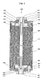
- a first embodiment where a non-aqueous electrolytic solution secondary battery according to the present invention is applied to a cylindrical lithium-ion battery for HEV will be explained below with reference to the drawing.
- a powdered lithium manganate (LiMn 2 O 4 ) serving as a positive electrode active material, a predetermined carbon serving as conductive material, which is described later, and a polyvinylidene fluoride (PVDF) as a binder are mixed at a predetermined ratio, the resultant mixture is added and mixed with N-methyl-2-pyrrolidone (NMP) as dispersion solvent to produce slurry.
- NMP N-methyl-2-pyrrolidone
- the slurry thus produced is applied to both surfaces of an aluminum foil W1 (positive electrode collector) having a thickness of 20 ⁇ m. At this time, a non-coated portion with a width of 30mm is left on one side edge, in a longitudinal direction, of the positive electrode.
- the aluminum foil W1 thus applied with the mixture is dried, pressed and cut to produce a positive electrode having a width of 82mm, a predetermined length and a predetermined thickness of the active material mixture applied portion.
- the apparent density of the positive electrode active material mixture layer W2 is set to 2. 65g/cm 3 .
- the non-coated portion is formed with notched portions, and the remaining portion thereof serves as positive electrode lead pieces 2.
- the distance or interval between the adjacent positive electrode lead pieces 2 is set to 50mm and the width of each positive electrode lead piece 2 is set to 5mm.
- a predetermined carbon powder is added with 8 weight parts of a polyvinylidene fluoride as a binder, and is further added and mixed with N-methyl-2-pyrrolidone as dispersion solvent to produce slurry.
- the slurry thus produced is applied to both surfaces of a rolled copper foil W3 (negative electrode collector) having a thickness of 10 ⁇ m. At this time, a non-coated portion with a width of 30mm is left on one side edge, in a longitudinal direction, of the negative electrode. Thereafter, the rolled copper foil W3 thus applied with the mixture is dried, pressed and cut to produce a negative electrode having a width of 86mm, a predetermined length and a predetermined thickness of the active material mixture applied portion.
- the negative electrode is pressed such that the porosity of the negative electrode active material mixture layer W4 is set to about 35%.
- the non-coated portion is formed with notched portions like the case of the positive electrode, and the remaining portion thereof serves as negative electrode lead pieces 3.
- the distance or interval between the adjacent negative electrode lead pieces 3 is set to 50mm and the width of each negative electrode lead piece 3 is set to 5mm.
- the positive electrode and the negative electrode thus manufactured are wound together with a separator W5 made of polyethylene and having a width of 90mm and a thickness of 40 ⁇ m such that both the electrodes do not come in direct contact with each other.
- a hollow cylindrical shaft rod 1 made of polypropylene is used at a center of the winding.
- the positive electrode lead pieces 2 and the negative electrode lead pieces 3 are respectively positioned at both end faces opposed to each other with respect to a winding group 6.
- the lengths of the positive electrode, the negative electrode and the separator are adjusted to set the diameter of the winding group 6 to 38 ⁇ 0.1mm.
- the positive electrode lead pieces 2 After all the positive electrode lead pieces 2 are deformed to be collected about and brought in contact with a peripheral face of a flange portion extended integrally from a periphery of a positive electrode collecting ring 4 positioned on an extension line of the shaft rod 1 of the winding group 6, the positive electrode lead pieces 2 and the peripheral face of the flange portion are welded to each other in a ultrasonic manner so that the positive electrode lead pieces 2 are connected to the peripheral face of the flange portion. Meanwhile, connecting operation between a negative electrode collecting ring 5 and the negative electrode lead pieces 3 is performed like the connecting operation between the positive electrode collecting ring 4 and the positive electrode lead pieces 2.
- insulating covering is applied on the entire circumferential surface of the flange portion of the positive electrode collecting ring 4.
- An adhesive tape comprising a base member made of polyimide and adhesive agent made of hexameta-acrylate and applied to one surface thereof is used for the insulating covering.
- This adhesive tape is wound at least one time from the peripheral surface of the flange portion to the outer peripheral surface of the winding group 6, thereby forming the insulating covering.
- the winding group 6 is inserted into a battery container 7 made of steel and nickel-plated.
- the outer diameter of the battery container 7 is 40mm and the inner diameter thereof is 39mm.
- a negative electrode lead plate 8 for electric conduction is welded to the negative electrode collecting ring 5 in advance, and after insertion of the winding group 6 into the battery container 7, a bottom portion of the battery container 7 and the negative electrode lead plate 8 are welded to each other.
- a positive electrode lead 9 configured by stacking a plurality of ribbons made of aluminum is welded to the positive electrode collecting ring 4 in advance, and the other end thereof is welded to a lower surface of a battery lid for sealing the battery container 7.
- the battery lid is provided with a cleavage valve 11 which cleaves according to an increase in battery internal pressure in the cylindrical lithium-ion battery 20 and which serves as an internal pressure releasing mechanism.
- the cleavage valve 11 is set to cleaving pressure of about 9 x 10 5 Pa.
- the battery lid comprises a lid case 12, a lid cap 13, a valve retainer 14 for keeping airtightness, and the cleavage valve 11, and the battery container is assembled by stacking these members to caulk a peripheral edge of the lid case 12.
- Non-aqueous electrolytic solution is injected to the battery container 7 by a predetermined amount, the battery lid is then fitted to the battery container 7 in a folding manner of the positive electrode lead 9, and the battery container 7 is sealed by performing caulking via a gasket 10 made of EPDM resin so that the cylindrical lithium-ion battery 20 is completed.
- the non-aqueous electrolytic solution is prepared previously in the following manner: A lithium hexafluorophosphate (LiPF 6 ) is dissolved at 1 mole/liter into mixed solution of ethylene carbonate, dimethyl carbonate and diethyl carbonate at a volume ratio of 1: 1: 1.
- the cylindrical lithium-ion battery 20 is not provided with a current shutting-off or reducing mechanism, for example, such as a PTC (Positive Temperature Coefficient) element or the like, which operates according to an increase in battery temperature.
- a current shutting-off or reducing mechanism for example, such as a PTC (Positive Temperature Coefficient) element or the like, which operates according to an increase in battery temperature.
- lithium manganate (LiMn 2 O 4 ) powder where the primary particle diameter was in a range of from about 1 to 2 ⁇ m, the secondary particle diameter was about 20 ⁇ m, the atom ratio (Li/Mn ratio) of Li to Mn was 0.52, scale-shaped graphite having an average particle diameter of 18 ⁇ m, and polyvinylidene fluoride were mixed at a composition ratio of 83: 12: 5 at weight %.
- the amount of application of the lithium manganate of the positive electrode active material mixture layer (active material applied portion) W2 per one side surface of the collector was 80g/m 2
- the thickness (which did not include the thickness of the collector) of the positive electrode active material mixture layer (active material applied portion) W2 was 73 ⁇ m
- the length of the positive electrode was 434cm.
- the average particle diameter of the scale-shaped graphite to the secondary particle diameter of the LiMn 2 O 4 was 0.9 times.
- MCMB which is mesophase system spherical graphite was used as the negative electrode active material.
- the thickness (which did not include the thickness of the collector) of the negative electrode active material mixture layer (active material applied portion) W4 was 53 ⁇ m, and the length thereof was 446 cm. Incidentally, the average particle diameter of the scale-shaped graphite can be adjusted by screening.
- the length of the negative electrode was set to be longer than that of the positive electrode by 12 cm such that, when wounded, the positive electrode did not protrude at the innermost layer of the winding from the negative electrode in a winding direction and the positive electrode did not protrude at the outermost layer of the winding from the negative electrode in the winding direction.
- the width of the negative electrode active material applied portion W4 was set to be longer than that of the positive electrode active material applied portion W2 by 4mm such that the positive electrode active material applied portion W2 did not protrude from the negative electrode active material applied portion W4 in a direction perpendicular to the winding direction (which is the same in the following Examples and Controls).
- Example 1-2 a battery was manufactured in the same manner as the Example 1-1 except that the amount of application of lithium manganate was 120 g/m 2 , the thickness (which did not include the thickness of the collector) of the positive electrode active material mixture layer (active material applied portion) W2 was 109 ⁇ m, the length of the positive electrode was 342cm, the thickness (which did not include the thickness of the collector) of the negative electrode active material mixture layer (active material applied portion) W4 was 79 ⁇ m, and the length of the negative electrode was 354cm.
- each battery was manufactured in the same manner as the Example 1-2 except that the Li/Mn ratio of lithium manganate was 0.55, 0.58, 0.60 or 0.61.
- Example 1-3 a battery was manufactured in the same manner as the Example 1-1 except that the amount of application of lithium manganate was 160 g/m 2 , the thickness (which did not include the thickness of the collector) of the positive electrode active material mixture layer (active material applied portion) W2 was 146 ⁇ m, the length of the positive electrode was 282cm, the thickness (which did not include the thickness of the collector) of the negative electrode active material mixture layer (active material applied portion) W4 was 106 ⁇ m, and the length of the negative electrode was 294cm.
- Example 1-4 a battery was manufactured in the following manner.
- the same lithium manganate powder as that in the Example 1-1, scale-shaped graphite having an average particle diameter of 18 ⁇ m (the average particle diameter of the scale-shaped graphite to the secondary particle of LiMn 2 O 4 : 0.9 times), and polyvinylidene fluoride were mixed at a composition ratio of 87: 8: 5 at weight %.
- the amount of application of the lithium manganate of the positive electrode active material mixture layer (active material applied portion) W2 per one side surface of the collector was 120g/m 2
- the thickness (which did not include the thickness of the collector) of the positive electrode active material mixture layer (active material applied portion) W2 was 104 ⁇ m
- the length of the positive electrode was 348cm.
- MCMB was used as the negative electrode active material.
- the thickness (which did not include the thickness of the collector) of the negative electrode active material mixture layer (active material applied portion) W4 was 79 ⁇ m, and the length thereof was 360 cm.
- Example 1-5 a battery was manufactured in the following manner.
- the same lithium manganate powder as that in the Example 1-1, scale-shaped graphite having an average particle diameter of 18 ⁇ m (the average particle diameter of the scale-shaped graphite to the secondary particle of LiMn 2 O 4 : 0.9 times), and polyvinylidene fluoride were mixed at a composition ratio of 79: 16: 5 at weight %.
- the amount of application of the lithium manganate of the positive electrode active material mixture layer (active material applied portion) W2 per one side surface of the collector was 120g/m 2
- the thickness (which did not include the thickness of the collector) of the positive electrode active material mixture layer (active material applied portion) W2 was 115 ⁇ m
- the length of the positive electrode was 336cm.
- MCMB was used as the negative electrode active material.
- the thickness (which did not include the thickness of the collector) of the negative electrode active material mixture layer (active material applied portion) W4 was 79 ⁇ m, and the length thereof was 348 cm.
- Example 1-6 a battery was manufactured in the following manner.
- the same lithium manganate powder as that in the Example 1-1, scale-shaped graphite having an average particle diameter of 18 ⁇ m (the average particle diameter of the scale-shaped graphite to the secondary particle of LiMn 2 O 4 : 0.9 times), ketjen black (KB) and polyvinylidene fluoride were mixed at a composition ratio of 83: 10: 2: 5 at weight %.
- the amount of application of the lithium manganate of the positive electrode active material mixture layer (active material applied portion) W2 per one side surface of the collector was 120g/m 2
- the thickness (which did not include the thickness of the collector) of the positive electrode active material mixture layer (active material applied portion) W2 was 109 ⁇ m
- the length of the positive electrode was 342cm.
- MCMB was used as the negative electrode active material.
- the thickness (which did not include the thickness of the collector) of the negative electrode active material mixture layer (active material applied portion) W4 was 79 ⁇ m, and the length thereof was 354 cm.
- Example 1-7 a battery was manufactured in the following manner.
- the same lithium manganate powder as that in the Example 1-1, scale-shaped graphite having an average particle diameter of 2 ⁇ m (the average particle diameter of the scale-shaped graphite to the secondary particle of LiMn 2 O 4 : 0.1 times), ketjen black (KB) and polyvinylidene fluoride were mixed at a composition ratio of 83: 10: 2: 5 at weight %.
- the amount of application of the lithium manganate of the positive electrode active material mixture layer (active material applied portion) W2 per one side surface of the collector was 120g/m 2
- the thickness (which did not include the thickness of the collector) of the positive electrode active material mixture layer (active material applied portion) W2 was 109 ⁇ m
- the length of the positive electrode was 342cm.
- MCMB was used as the negative electrode active material.
- the thickness (which did not include the thickness of the collector) of the negative electrode active material mixture layer (active material applied portion) W4 was 79 ⁇ m, and the length thereof was 354 cm.
- Example 1-8 a battery was manufactured in the following manner.
- the same lithium manganate powder as that in the Example 1-1, scale-shaped graphite having an average particle diameter of 4 ⁇ m (the average particle diameter of the scale-shaped graphite to the secondary particle of LiMn 2 O 4 : 0.2 times), ketjen black (KB) and polyvinylidene fluoride were mixed at a composition ratio of 83: 10: 2: 5 at weight %.
- the amount of application of the lithium manganate of the positive electrode active material mixture layer (active material applied portion) W2 per one side surface of the collector was 120g/m 2
- the thickness (which did not include the thickness of the collector) of the positive electrode active material mixture layer (active material applied portion) W2 was 109 ⁇ m
- the length of the positive electrode was 342cm.
- MCMB was used as the negative electrode active material.
- the thickness (which did not include the thickness of the collector) of the negative electrode active material mixture layer (active material applied portion) W4 was 79 ⁇ m, and the length thereof was 354 cm.
- Example 1-9 a battery was manufactured in the following manner.
- the same lithium manganate powder as that in the Example 1-1, scale-shaped graphite having an average particle diameter of 10 ⁇ m (the average particle diameter of the scale-shaped graphite to the secondary particle of LiMn 2 O 4 : 0.5 times), ketjen black (KB) and polyvinylidene fluoride were mixed at a composition ratio of 83: 10: 2: 5 at weight %.
- the amount of application of the lithium manganate of the positive electrode active material mixture layer (active material applied portion) W2 per one side surface of the collector was 120g/m 2
- the thickness (which did not include the thickness of the collector) of the positive electrode active material mixture layer (active material applied portion) W2 was 109 ⁇ m
- the length of the positive electrode was 342cm.
- MCMB was used as the negative electrode active material.
- the thickness (which did not include the thickness of the collector) of the negative electrode active material mixture layer (active material applied portion) W4 was 79 ⁇ m, and the length thereof was 354 cm.
- Example 1-10 a battery was manufactured in the following manner.
- the same lithium manganate powder as that in the Example 1-1, scale-shaped graphite having an average particle diameter of 16 ⁇ m (the average particle diameter of the scale-shaped graphite to the secondary particle of LiMn 2 O 4 : 0.8 times), ketjen black (KB) and polyvinylidene fluoride were mixed at a composition ratio of 83: 10: 2: 5 at weight %.
- the amount of application of the lithium manganate of the positive electrode active material mixture layer (active material applied portion) W2 per one side surface of the collector was 120g/m 2
- the thickness (which did not include the thickness of the collector) of the positive electrode active material mixture layer (active material applied portion) W2 was 109 ⁇ m
- the length of the positive electrode was 342cm.
- MCMB was used as the negative electrode active material.
- the thickness (which did not include the thickness of the collector) of the negative electrode active material mixture layer (active material applied portion) W4 was 79 ⁇ m, and the length thereof was 354 cm.
- Example 1-11 a battery was manufactured in the following manner.
- the same lithium manganate power as that in the Example 1-1, scale-shaped graphite having an average particle diameter of 10 ⁇ m (the average particle diameter of the scale-shaped graphite to the secondary particle of LiMn 2 O 4 : 0.5 times), acetylene black (AB) and polyvinylidene fluoride were mixed at a composition ratio of 83: 10: 2: 5 at weight %.
- the amount of application of the lithium manganate of the positive electrode active material mixture layer (active material applied portion) W2 per one side surface of the collector was 120g/m 2
- the thickness (which did not include the thickness of the collector) of the positive electrode active material mixture layer (active material applied portion) W2 was 109 ⁇ m
- the length of the positive electrode was 342cm.
- MCMB was used as the negative electrode active material.
- the thickness (which did not include the thickness of the collector) of the negative electrode active material mixture layer (active material applied portion) W4 was 79 ⁇ m, and the length thereof was 354 cm.
- Example 1-12 a battery was manufactured in the following manner.
- Lithium manganate (LiMn 2 O 4 ) powder where the primary particle diameter was about 1 to 2 ⁇ m, the secondary particle diameter was about 20 ⁇ m, the atom ratio (Li/Mn ratio) of Li to Mn was 0.55, scale-shaped graphite having an average particle diameter of 10 ⁇ m (average particle diameter of scale-shaped graphite to the secondary particle diameter of LiMn 2 O 4 : 0.5 times), acetylene black (AB), and polyvinylidene fluoride were mixed at a composition ratio of 83: 10: 2: 5 at weight %.
- the amount of application of the lithium manganate of the positive electrode active material mixture layer (active material applied portion) W2 per one side surface of the collector was 120g/m 2
- the thickness (which did not include the thickness of the collector) of the positive electrode active material mixture layer (active material applied portion) W2 was 109 ⁇ m
- the length of the positive electrode was 342cm.
- MCMB was used as the negative electrode active material.
- the thickness (which did not include the thickness of the collector) of the negative electrode active material mixture layer (active material applied portion) W4 was 79 ⁇ m, and the length thereof was 354 cm.
- Example 1-13 a battery was manufactured in the following manner.
- Lithiummanganate (LiMn 2 O 4 ) powder where the primary particle diameter was about 1 to 2 ⁇ m, the secondary particle diameter was about 20 ⁇ m, the atom ratio (Li/Mn ratio) of Li to Mn was 0.58, scale-shaped graphite having an average particle diameter of 10 ⁇ m (average particle diameter of scale-shaped graphite to the secondary particle diameter of LiMn 2 O 4 : 0.5 times), acetylene black (AB), and polyvinylidene fluoride were mixed at a composition ratio of 83: 10: 2: 5 at weight %.
- the amount of application of the lithium manganate of the positive electrode active material mixture layer (active material applied portion) W2 per one side surface of the collector was 120g/m 2
- the thickness (which did not include the thickness of the collector) of the positive electrode active material mixture layer (active material applied portion) W2 was 109 ⁇ m
- the length of the positive electrode was 342cm.
- MCMB was used as the negative electrode active material.
- the thickness (which did not include the thickness of the collector) of the negative electrode active material mixture layer (active material applied portion) W4 was 79 ⁇ m, and the length thereof was 354 cm.
- Example 1-14 a battery was manufactured in the following manner.
- Lithium manganate (LiMn 2 O 4 ) powder where the primary particle diameter was about 1 to 2 ⁇ m, the secondary particle diameter was about 20 ⁇ m, the atom ratio (Li/Mn ratio) of Li to Mn was 0.60, scale-shaped graphite having an average particle diameter of 10 ⁇ m (average particle diameter of scale-shaped graphite to the secondary particle diameter of LiMn 2 O 4 : 0.5 times), acetylene black (AB), and polyvinylidene fluoride were mixed at a composition ratio of 83: 10: 2: 5 at weight %.
- the amount of application of the lithium manganate of the positive electrode active material mixture layer (active material applied portion) W2 per one side surface of the collector was 120g/m 2
- the thickness (which did not include the thickness of the collector) of the positive electrode active material mixture layer (active material applied portion) W2 was 109 ⁇ m
- the length of the positive electrode was 342cm.
- MCMB was used as the negative electrode active material.
- the thickness (which did not include the thickness of the collector) of the negative electrode active material mixture layer (active material applied portion) W4 was 79 ⁇ m, and the length thereof was 354 cm.
- Example 1-15 a battery was manufactured in the following manner.
- Lithium manganate (LiMn 2 O 4 ) powder where the primary particle diameter was about 1 to 2 ⁇ m, the secondary particle diameter was about 20 ⁇ m, the atom ratio (Li/Mn ratio) of Li to Mn was 0.61, scale-shaped graphite having an average particle diameter of 10 ⁇ m (average particle diameter of scale-shaped graphite to the secondary particle diameter of LiMn 2 O 4 : 0.5 times), acetylene black (AB), and polyvinylidene fluoride were mixed at a composition ratio of 83: 10: 2: 5 at weight %.
- the amount of application of the lithium manganate of the positive electrode active material mixture layer (active material applied portion) W2 per one side surface of the collector was 120g/m 2
- the thickness (which did not include the thickness of the collector) of the positive electrode active material mixture layer (active material applied portion) W2 was 109 ⁇ m
- the length of the positive electrode was 342cm.
- MCMB was used as the negative electrode active material.
- the thickness (which did not include the thickness of the collector) of the negative electrode active material mixture layer (active material applied portion) W4 was 79 ⁇ m, and the length thereof was 354 cm.
- Example 1-16 a battery was manufactured in the following manner.
- the same lithium manganate powder as that in the Example 1-1, scale-shaped graphite having an average particle diameter of 10 ⁇ m (average particle diameter of scale-shaped graphite to the secondary particle diameter of LiMn 2 O 4 : 0.5 times), acetylene black (AB), and polyvinylidene fluoride were mixed at a composition ratio of 83: 10: 2: 5 at weight %.
- the amount of application of the lithium manganate of the positive electrode active material mixture layer (active material applied portion) W2 per one side surface of the collector was 120g/m 2
- the thickness (which did not include the thickness of the collector) of the positive electrode active material mixture layer (active material applied portion) W2 was 109 ⁇ m
- the length of the positive electrode was 342cm.
- amorphous carbon was used as the negative electrode active material.
- the thickness (which did not include the thickness of the collector) of the negative electrode active material mixture layer (active material applied portion) W4 was 79 ⁇ m, and the length thereof was 354 cm.
- each battery was manufactured in the same manner as the Example 1-16 except that the Li/Mn ratio of lithium manganate was 0.55, 0.58, 0.60 or 0.61.
- Example 1-17 a battery was manufactured in the following manner.
- the same lithium manganate powder as that in the Example 1-1, scale-shaped graphite having an average particle diameter of 10 ⁇ m (the average particle diameter of the scale-shaped graphite to the secondary particle of LiMn 2 O 4 : 0.5 times), and polyvinylidene fluoride were mixed at a composition ratio of 83: 12: 5 at weight %.
- the amount of application of the lithium manganate of the positive electrode active material mixture layer (active material applied portion) W2 per one side surface of the collector was 120g/m 2
- the thickness (which did not include the thickness of the collector) of the positive electrode active material mixture layer (active material applied portion) W2 was 109 ⁇ m
- the length of the positive electrode was 342cm.
- amorphous carbon was used as the negative electrode active material.
- the thickness (which did not include the thickness of the collector) of the negative electrode active material mixture layer (active material applied portion) W4 was 79 ⁇ m, and the length thereof was 354 cm.
- each battery was manufactured in the same manner as the Example 1-17 except that the Li/Mn ratio of lithium manganate was 0.55, 0.58, 0.60 or 0.61.
- a battery was manufactured in the same manner as the Example 1-1 except that the amount of application of lithium manganate was 75g/m 2 , the thickness (which did not include the thickness of the collector) of the positive electrode active material mixture layer (active material applied portion) was 68 ⁇ m, the length of the positive electrode was 450cm, the thickness (which did not include the thickness of the collector) of the negative electrode active material mixture layer (active material applied portion) was 50 ⁇ m, and the length of the negative electrode was 462cm.
- a battery was manufactured in the same manner as the Example 1-1 except that the amount of application of lithium manganate was 165g/m 2 , the thickness (which did not include the thickness of the collector) of the positive electrode active material mixture layer (active material applied portion) was 150 ⁇ m, the length of the positive electrode was 276cm, the thickness (which did not include the thickness of the collector) of the negative electrode active material mixture layer (active material applied portion) was 109 ⁇ m, and the length of the negative electrode was 288cm.
- a battery was manufactured in the following manner.
- the same lithium manganate powder as that in the Example 1-1, scale-shaped graphite having an average particle diameter of 18 ⁇ m (the average particle diameter of the scale-shaped graphite to the secondary particle of LiMn 2 O 4 : 0.9 times), and polyvinylidene fluoride were mixed at a composition ratio of 88: 7: 5 at weight %.
- the amount of application of the lithium manganate of the positive electrode active material mixture layer (active material applied portion) per one side surface of the collector was 120g/m 2
- the thickness (which did not include the thickness of the collector) of the positive electrode active material mixture layer (active material applied portion) was 103 ⁇ m
- the length of the positive electrode was 349cm.
- MCMB was used as the negative electrode active material.
- the thickness (which did not include the thickness of the collector) of the negative electrode active material mixture layer (active material applied portion) was 80 ⁇ m, and the length thereof was 361 cm.
- a battery was manufactured in the following manner.
- the same lithium manganate powder as that in the Example 1-1, scale-shaped graphite having an average particle diameter of 18 ⁇ m (the average particle diameter of the scale-shaped graphite to the secondary particle of LiMn 2 O 4 : 0.9 times), and polyvinylidene fluoride were mixed at a composition ratio of 78: 17: 5 at weight %.
- the amount of application of the lithium manganate of the positive electrode active material mixture layer (active material applied portion) per one side surface of the collector was 120g/m 2
- the thickness (which did not include the thickness of the collector) of the positive electrode active material mixture layer (active material applied portion) was 116 ⁇ m
- the length of the positive electrode was 334cm.
- MCMB was used as the negative electrode active material.
- the thickness (which did not include the thickness of the collector) of the negative electrode active material mixture layer (active material applied portion) was 80 ⁇ m, and the length thereof was 346 cm.
- the charging conditions were set on a constant voltage of 4.2V, a limiting current of 5A, and a charging time of 3.5 hours.
- the discharging conditions were set on a constant current of 5A and a final voltage of 2.7V.
- the discharging power of each battery which was put in a charged state was measured under the above conditions.
- the measuring conditions were as follows: Each voltage of the fifth second at each discharging current of 1A, 3A, and 6A was read and plotted on the vertical axis to the current value of the horizontal axis, where a straight line in which an approximate collinear was performed by three points reached a final voltage 2.7V, the product of the current value by the 2.7V was calculated as the initial power for each battery.
- the power (capacity) of the 100th cycle was measured. Then, a percentage of the power of the 100th cycle to the initial power (hereinafter, called "power retaining percentage") was calculated. It goes without saying that, the higher the power retaining percentage is, the more excellent the life characteristic is.
- each battery manufactured was continuously charged at the room temperature with a constant current of 20A, and its behavior was observed.
- the test results are shown in the following Table 2.
- Such a phenomenon of gas discharging constituted with volatile material of electrolytic solution occurred after the cleavage valve was cleaved.
- the temperatures of battery surfaces just after the phenomena occurred were measured.
- presence/absence of deformation in each battery container was observed.
- a circle mark indicates a battery whose battery container was not deformed at all
- a delta mark indicates a battery whose battery container was slightly deformed
- a mark "X" indicates a battery whose battery container was largely deformed.
- the amount of graphite in the positive electrode conductive material was below 8 weight %, which resulted in lowering of the power.
- the battery of Control 1-4 where the amount of graphite in the positive electrode conductive material exceeded 16 weight %, high capacity and high power were obtained, but the battery behavior during continuous charging was violent, and the battery surface temperature resulted in 310°C.
- Example 1-15 In each battery of Examples 1-12 to 1-14, Examples 1-2-2 to 1-2-4, Examples 1-16-2 to 1-16-4, and Examples 1-17-2 to 1-17-4, where Li/Mn ratio of lithium manganate was 0.55 or more, its power retaining percentage was very high.
- Example 1-2-5, Example 1-16-5, and Example 1-17-5 where Li/Mn ratio of lithium manganate was above 0.60, lowering of capacity was caused. Therefore, it is found that the Li/Mn ratio is preferably in the range of from 0.55 to 0.60.
- Example 1-16 In each battery of Example 1-16, Examples 1-16-2 to 1-16-5, Example 1-17, and Examples 1-17-2 to 1-17-5, where amorphous carbon was used the negative electrode, a remarkably high power, a remarkably power retaining percentage and a lowermost battery surface temperature during continuous charging could be obtained. Accordingly, each battery of these Examples 1-16, 1-16-2 to 1-16-5, 1-17, and 1-17-2 to 1-17-5 was one which has a high capacity, a high power and an excellent safety and which was well balanced generally.
- the cylindrical lithium-ion battery 20 is a battery whose behavior is remarkably calm even when it is put in an abnormal state and which has an excellent safety.
- a battery having a high capacity and a high power, and whose safety is considerably high is suitable for a power supply for HEV.
- a powdered lithium manganate (LiMn 2 O 4 ) serving as a positive electrode active material, a predetermined carbon serving as conductive material, which is described later, and a polyvinylidene fluoride (PVDF) as a binder are mixed at a predetermined ratio, the resultant mixture is added and mixed with N-methyl-2-pyrrolidone (NMP) as dispersion solvent to produce slurry.
- NMP N-methyl-2-pyrrolidone
- the slurry thus produced is applied to both surfaces of an aluminum foil (positive electrode collector) having a thickness of 20 ⁇ m. At this time, a non-coated portion with a width of 50mm is left on one side edge, in a longitudinal direction, of the positive electrode.
- the aluminum foil W1 thus applied with the mixture is dried, pressed and cut to produce a positive electrode having a width of 300mm, a predetermined length and a predetermined thickness of the active material mixture applied portion.
- the apparent density of the positive electrode active material mixture layer is set to 2.65g/cm 3 .
- the non-coated portion is formed with notched portions, and the remaining portion thereof serves as positive electrode lead pieces.
- the distance or interval between the adjacent positive electrode lead pieces is set to 50mm and the width of each positive electrode lead piece is set to 10mm.
- 92 weight parts of a predetermined carbon powder from/in which lithium ions can be released/occluded through charging/discharging is added with 8 weight parts of a polyvinylidene fluoride as a binder, and is further added and mixed with N-methyl-2-pyrrolidone as dispersion solvent to produce slurry.
- the slurry thus produced is applied to both surfaces of a rolled copper foil (negative electrode collector) having a thickness of 10 ⁇ m. At this time, a non-coated portion with a width of 50mm is left on one side edge, in a longitudinal direction, of the negative electrode.
- the copper foil thus applied with the mixture is dried, pressed and cut to produce a negative electrode having a width of 305mm, a predetermined length and a predetermined thickness of the active material mixture applied portion described later.
- the negative electrode is pressed such that the porosity of the negative electrode mixture layer is set to about 35%.
- the non-coated portion is formed with notched portions like the case of the positive electrode, and the remaining portion thereof serves as negative electrode lead pieces.
- the distance or interval between the adjacent negative electrode lead pieces is set to 50mm and the width of each positive electrode lead piece is set to 10mm.
- the positive electrode and the negative electrode manufactured in the above manner are wound together with a separator made of polyethylene and having a width of 310mm and a thickness of 40 ⁇ m such that both the electrodes do not come in direct contact with each other.
- lead pieces 109 of the positive electrode and the negative electrode are respectively positioned at both end faces opposed to each other with respect to a winding group 106.
- the lengths of the positive electrode, the negative electrode and the separator are adjusted to set the diameter of the winding group 106 to 65 ⁇ 0.1mm.
- insulating covering 108 is applied on the entire circumferential surfaces of the flange portions 107 of the positive electrode external terminal 101 and the negative electrode external terminal 101'.
- This insulating covering 108 is applied to the entire outer peripheral surface of the winding group 106.
- An adhesive tape comprising a base member made of polyimide and adhesive agent made of hexameta-acrylate and applied to one surface thereof is used for the insulating covering 108.
- This adhesive tape is wound several times from the peripheral surface of the flange portion 107 to the outer peripheral surface of the winding group 106, thereby forming the insulating covering 108.
- the number of windings is adjusted such that the maximum diameter portion of the winding group 106 is a portion where the insulating covering 108 exists.
- the maximum diameter is set to be slightly smaller than an inner diameter of a battery container 105, and the winding group 106 is inserted into the battery container 105 made of steel and nickel-plated.
- the outer diameter of the battery container 105 is 67mm and the inner diameter thereof is 66mm.
- second ceramic washers 103' are respectively fitted on the pole stud whose distal end constitutes the positive electrode external terminal 101 and the pole stud whose distal end constitutes the negative electrode external terminal 101'.
- Each second ceramic washer 103' is made of alumina and has a portion abutting on a back face of a disk-shaped battery lid 104, the abutting portion having a thickness of 2 mm, an inner diameter of 16 mm and an outer diameter of 25 mm.
- alumina-made first planer ceramic washers 103 are respectively placed on the battery lids 104, and the positive electrode external terminal 101 and the negative electrode external terminal 101' are respectively inserted into the first ceramic washers 103.
- Each first planer ceramic washer 103 has a thickness of 2 mm, an inner diameter of 16 mm and an outer diameter of 28 mm. Then, peripheral faces of the battery lids 104 are fitted to openings of the battery container 105 and the entire contacting portion between the lids 104 and the battery container 105 is laser-welded. At this time, the positive electrode external terminal 101 and the negative electrode external terminal 101' project outside the battery lids 104 through holes formed at centers of the battery lids 104.
- the first ceramic washer 103 and a metal washer 114 which is smoother than the bottom face of a metal nut 102 are fitted on each of the positive electrode external terminal 101 and the negative electrode external terminal 101' in this order.
- a cleavage valve 110 which cleaves according to an increase in battery internal pressure is equipped with one of the battery lids 104.
- the cleavage valve 110 is set to cleaving pressure of 1.3 x 10 6 to 1.8 x 10 6 Pa (130 to 180 N/cm 2 ).
- the nuts 102 are respectively screwed to the positive electrode external terminal 101 and the negative electrode external terminal 101', and the battery lids 104 are fastened between the flange portions 107 and the nuts 102 via the second ceramic washers 103', the first ceramic washers 103 and the metal washers 114.
- a fastening torque value at this time is set to about 7Nm.
- the metal washers 114 were not rotated until the fastening work was completed.
- electricity generating elements inside the battery container 105 are sealed from the outside by compression of O-rings 116 which are made of rubber (EPDM) and are interposed between the back face of the battery lid 104 and the flange portion 107.
- a predetermined amount of non-aqueous electrolytic solution is injected to the battery container 105 from a injecting port 115 provided at the battery lid 104, and the cylindrical lithium-ion battery 120 is completed by sealing the injecting port 115.
- the non-aqueous electrolytic solution is prepared previously in the following manner: A lithium hexafluorophosphate (LiPF 6 ) is dissolved at 1 mole/liter into mixed solution of ethylene carbonate, dimethyl carbonate and diethyl carbonate at a volume ratio of 1: 1: 1.
- the cylindrical lithium-ion battery 120 is not provided with a current shutting-off or reducing mechanism, for example, such as a PTC (Positive Temperature Coefficient) element or the like, which shuts off or reduces current according to an increase in battery temperature in the battery container 105.
- a current shutting-off or reducing mechanism for example, such as a PTC (Positive Temperature Coefficient) element or the like, which shuts off or reduces current according to an increase in battery temperature in the battery container 105.
- Example 2-1 a battery was manufactured in the following manner. Lithiummanganate (LiMn 2 O 4 ) powder where the primary particle diameter was about 1 to 2 ⁇ m, the secondary particle diameter was about 20 ⁇ m, the atom ratio (Li/Mn ratio) of Li to Mn was 0.52, scale-shaped graphite having an average particle diameter of 18 ⁇ m, and polyvinylidene fluoride were mixed at a composition ratio of 90: 5: 5 at weight %.
- Lithiummanganate (LiMn 2 O 4 ) powder where the primary particle diameter was about 1 to 2 ⁇ m, the secondary particle diameter was about 20 ⁇ m, the atom ratio (Li/Mn ratio) of Li to Mn was 0.52, scale-shaped graphite having an average particle diameter of 18 ⁇ m, and polyvinylidene fluoride were mixed at a composition ratio of 90: 5: 5 at weight %.
- the amount of application of the lithium manganate of the positive electrode active material mixture layer (active material applied portion) per one side surface of the collector was 270g/m 2
- the thickness (which did not include the thickness of the collector) of the positive electrode active material mixture layer (active material applied portion) was 226 ⁇ m
- the length of the positive electrode was 615cm.
- the average particle diameter of the scale-shaped graphite to secondary particle diameter of the LiMn 2 O 4 was 0.9 times.
- MCMB which is mesophase system spherical graphite was used as the negative electrode active material.
- the thickness (which did not include the thickness of the collector) of the negative electrode active material mixture layer (active material applied portion) was 150 ⁇ m, and the length thereof was 633 cm.
- the average particle diameter of the scale-shaped graphite can be adjusted by screening.
- the length of the negative electrode was set to be longer than that of the positive electrode by 18 cm such that, when wounded, the positive electrode did not protrude at the innermost layer of the winding from the negative electrode in a winding direction and the positive electrode did not protrude at the outermost layer of the winding from the negative electrode in the winding direction.
- the width of the negative electrode active material applied portion was set to be longer than that of the positive electrode active material applied portion by 5mm such that the positive electrode active material applied portion did not protrude from the negative electrode active material applied portion in a direction perpendicular to the winding direction (which is the same in the following Examples and Controls).
- Example 2-2 a battery was manufactured in the same manner as the Example 2-1 except that the amount of application of lithium manganate was 300 g/m 2 , the thickness (which did not include the thickness of the collector) of the positive electrode active material mixture layer (active material applied portion) was 252 ⁇ m, the length of the positive electrode was 565cm, the thickness (which did not include the thickness of the collector) of the negative electrode active material mixture layer (active material applied portion) was 166 ⁇ m, and the length of the negative electrode was 583cm.
- each battery was manufactured in the same manner as the Example 2-2 except that the Li/Mn ratio of lithium manganate was 0.55, 0.58, 0.60 or 0.61.
- Example 2-3 a battery was manufactured in the same manner as the Example 2-1 except that the amount of application of lithium manganate was 330 g/m 2 , the thickness (which did not include the thickness of the collector) of the positive electrode active material mixture layer (active material applied portion) was 277 ⁇ m, the length of the positive electrode was 523cm, the thickness (which did not include the thickness of the collector) of the negative electrode active material mixture layer (active material applied portion) was 183 ⁇ m, and the length of the negative electrode was 541cm.
- Example 2-4 a battery was manufactured in the following manner.
- the same lithium manganate powder as that in the Example 2-1, scale-shaped graphite having an average particle diameter of 18 ⁇ m (the average particle diameter of the scale-shaped graphite to the secondary particle of LiMn 2 O 4 : 0.9 times), and polyvinylidene fluoride were mixed at a composition ratio of 90: 3: 7 at weight %.
- the amount of application of the lithium manganate of the positive electrode active material mixture layer (active material applied portion) per one side surface of the collector was 300g/m 2
- the thickness (which did not include the thickness of the collector) of the positive electrode active material mixture layer (active material applied portion) was 252 ⁇ m
- the length of the positive electrode was 565cm.
- MCMB was used as the negative electrode active material.
- the thickness (which did not include the thickness of the collector) of the negative electrode active material mixture layer (active material applied portion) was 166 ⁇ m, and the length thereof was 583 cm.
- Example 2-5 a battery was manufactured in the same manner.
- the same lithium manganate powder as that in the Example 2-1, scale-shaped graphite having an average particle diameter of 18 ⁇ m (the average particle diameter of the scale-shaped graphite to the secondary particle of LiMn 2 O 4 : 0.9 times), and polyvinylidene fluoride were mixed at a composition ratio of 90: 7: 3 at weight %.
- the amount of application of the lithium manganate of the positive electrode active material mixture layer (active material applied portion) per one side surface of the collector was 300g/m 2
- the thickness (which did not include the thickness of the collector) of the positive electrode active material mixture layer (active material applied portion) was 260 ⁇ m
- the length of the positive electrode was 556cm.
- MCMB was used as the negative electrode active material.
- the thickness (which did not include the thickness of the collector) of the negative electrode active material mixture layer (active material applied portion) was 166 ⁇ m, and the length thereof was 574 cm.
- Example 2-6 a battery was manufactured in the following manner.
- the same lithium manganate powder as that in the Example 2-1, scale-shaped graphite having an average particle diameter of 18 ⁇ m (the average particle diameter of the scale-shaped graphite to the secondary particle of LiMn 2 O 4 : 0.9 times), ketj en black (KB) and polyvinylidene fluoride were mixed at a composition ratio of 90: 4: 1: 5 at weight %.
- the amount of application of the lithium manganate of the positive electrode active material mixture layer (active material applied portion) per one side surface of the collector was 300g/m 2
- the thickness (which did not include the thickness of the collector) of the positive electrode active material mixture layer (active material applied portion) was 252 ⁇ m
- the length of the positive electrode was 565cm.
- MCMB was used as the negative electrode active material.
- the thickness (which did not include the thickness of the collector) of the negative electrode active material mixture layer (active material applied portion) was 166 ⁇ m, and the length thereof was 583 cm.
- Example 2-7 a battery was manufactured in the following manner.
- the same lithium manganate powder as that in the Example 2-1, scale-shaped graphite having an average particle diameter of 2 ⁇ m (the average particle diameter of the scale-shaped graphite to the secondary particle of LiMn 2 O 4 : 0.1 times), ketjen black (KB) and polyvinylidene fluoride were mixed at a composition ratio of 90: 4: 1: 5 at weight %.
- the amount of application of the lithium manganate of the positive electrode active material mixture layer (active material applied portion) per one side surface of the collector was 300g/m 2
- the thickness (which did not include the thickness of the collector) of the positive electrode active material mixture layer (active material applied portion) was 252 ⁇ m
- the length of the positive electrode was 565cm.
- MCMB was used as the negative electrode active material.
- the thickness (which did not include the thickness of the collector) of the negative electrode active material mixture layer (active material applied portion) was 166 ⁇ m, and the length thereof was 583 cm.
- Example 2-8 a battery was manufactured in the following manner.
- the same lithium manganate powder as that in the Example 2-1, scale-shaped graphite having an average particle diameter of 4 ⁇ m (the average particle diameter of the scale-shaped graphite to the secondary particle of LiMn 2 O 4 : 0.2 times), ketjen black (KB) and polyvinylidene fluoride were mixed at a composition ratio of 90: 4: 1: 5 at weight %.
- the amount of application of the lithium manganate of the positive electrode active material mixture layer (active material applied portion) per one side surface of the collector was 300g/m 2
- the thickness (which did not include the thickness of the collector) of the positive electrode active material mixture layer (active material applied portion) was 252 ⁇ m
- the length of the positive electrode was 565cm.
- MCMB was used as the negative electrode active material.
- the thickness (which did not include the thickness of the collector) of the negative electrode active material mixture layer (active material applied portion) was 166 ⁇ m, and the length thereof was 583 cm.
- Example 2-9 a battery was manufactured in the following manner.
- the same lithium manganate powder as that in the Example 2-1, scale-shaped graphite having an average particle diameter of 10 ⁇ m (the average particle diameter of the scale-shaped graphite to the secondary particle of LiMn 2 O 4 : 0.5 times), ketjen black (KB) and polyvinylidene fluoride were mixed at a composition ratio of 90: 4: 1: 5 at weight %.
- the amount of application of the lithium manganate of the positive electrode active material mixture layer (active material applied portion) per one side surface of the collector was 300g/m 2
- the thickness (which did not include the thickness of the collector) of the positive electrode active material mixture layer (active material applied portion) was 252 ⁇ m
- the length of the positive electrode was 565cm.
- MCMB was used as the negative electrode active material.
- the thickness (which did not include the thickness of the collector) of the negative electrode active material mixture layer (active material applied portion) was 166 ⁇ m, and the length thereof was 583 cm.
- Example 2-10 a battery was manufactured in the following manner.
- the same lithium manganate powder as that in the Example 2-1, scale-shaped graphite having an average particle diameter of 16 ⁇ m (the average particle diameter of the scale-shaped graphite to the secondary particle of LiMn 2 O 4 : 0.8 times), ketj en black (KB) and polyvinylidene fluoride were mixed at a composition ratio of 90: 4: 1: 5 at weight %.
- the amount of application of the lithium manganate of the positive electrode active material mixture layer (active material applied portion) per one side surface of the collector was 300g/m 2
- the thickness (which did not include the thickness of the collector) of the positive electrode active material mixture layer (active material applied portion) was 252 ⁇ m
- the length of the positive electrode was 565cm.
- MCMB was used as the negative electrode active material.
- the thickness (which did not include the thickness of the collector) of the negative electrode active material mixture layer (active material applied portion) was 166 ⁇ m, and the length thereof was 583 cm.
- Example 2-11 a battery was manufactured in the following manner.
- the same lithium manganate power as that in the Example 2-1, scale-shaped graphite having an average particle diameter of 10 ⁇ m (the average particle diameter of the scale-shaped graphite to the secondary particle of LiMn 2 O 4 : 0.5 times), ketjen black (KB) and polyvinylidene fluoride were mixed at a composition ratio of 90: 4: 1: 5 at weight %.
- the amount of application of the lithium manganate of the positive electrode active material mixture layer (active material applied portion) per one side surface of the collector was 300g/m 2
- the thickness (which did not include the thickness of the collector) of the positive electrode active material mixture layer (active material applied portion) was 252 ⁇ m
- the length of the positive electrode was 565cm.
- MCMB was used as the negative electrode active material.
- the thickness (which did not include the thickness of the collector) of the negative electrode active material mixture layer (active material applied portion) was 166 ⁇ m, and the length thereof was 583 cm.
- Example 2-12 a battery was manufactured in the following manner.
- Lithium manganate (LiMn 2 O 4 ) powder where the primary particle diameter was about 1 to 2 ⁇ m, the secondary particle diameter was about 20 ⁇ m, the atom ratio (Li/Mn ratio) of Li to Mn was 0.55, scale-shaped graphite having an average particle diameter of 10 ⁇ m (average particle diameter of scale-shaped graphite to the secondary particle diameter of LiMn 2 O 4 : 0.5 times), acetylene black (AB), and polyvinylidene fluoride were mixed at a composition ratio of 90: 4: 1: 5 at weight %.
- the amount of application of the lithium manganate of the positive electrode active material mixture layer (active material applied portion) per one side surface of the collector was 300g/m 2
- the thickness (which did not include the thickness of the collector) of the positive electrode active material mixture layer (active material applied portion) was 252 ⁇ m
- the length of the positive electrode was 565cm.
- MCMB was used as the negative electrode active material.
- the thickness (which did not include the thickness of the collector) of the negative electrode active material mixture layer (active material applied portion) was 166 ⁇ m, and the length thereof was 583 cm.
- Example 2-13 a battery was manufactured in the following manner.
- Lithium manganate (LiMn 2 O 4 ) powder where the primary particle diameter was about 1 to 2 ⁇ m, the secondary particle diameter was about 20 ⁇ m, the atom ratio (Li/Mn ratio) of Li to Mn was 0.58, scale-shaped graphite having an average particle diameter of 10 ⁇ m (average particle diameter of scale-shaped graphite to the secondary particle diameter of LiMn 2 O 4 : 0.5 times), acetylene black (AB), and polyvinylidene fluoride were mixed at a composition ratio of 90: 4: 1: 5 at weight %.
- the amount of application of the lithium manganate of the positive electrode active material mixture layer (active material applied portion) per one side surface of the collector was 300g/m 2
- the thickness (which did not include the thickness of the collector) of the positive electrode active material mixture layer (active material applied portion) was 252 ⁇ m
- the length of the positive electrode was 565cm.
- MCMB was used as the negative electrode active material.
- the thickness (which did not include the thickness of the collector) of the negative electrode active material mixture layer (active material applied portion) was 166 ⁇ m, and the length thereof was 583 cm.
- Example 2-14 a battery was manufactured in the following manner.
- Lithium manganate (LiMn 2 O 4 ) powder where the primary particle diameter was about 1 to 2 ⁇ m, the secondary particle diameter was about 20 ⁇ m, the atom ratio (Li/Mn ratio) of Li to Mn was 0.60, scale-shaped graphite having an average particle diameter of 10 ⁇ m (average particle diameter of scale-shaped graphite to the secondary particle diameter of LiMn 2 O 4 : 0.5 times), acetylene black (AB), and polyvinylidene fluoride were mixed at a composition ratio of 90: 4: 1: 5 at weight %.
- the amount of application of the lithium manganate of the positive electrode active material mixture layer (active material applied portion) per one side surface of the collector was 300g/m 2
- the thickness (which did not include the thickness of the collector) of the positive electrode active material mixture layer (active material applied portion) was 252 ⁇ m
- the length of the positive electrode was 565cm.
- MCMB was used as the negative electrode active material.
- the thickness (which did not include the thickness of the collector) of the negative electrode active material mixture layer (active material applied portion) was 166 ⁇ m, and the length thereof was 583 cm.
- Example 2-15 a battery was manufactured in the following manner.
- Lithium manganate (LiMn 2 O 4 ) powder where the primary particle diameter was about 1 to 2 ⁇ m, the secondary particle diameter was about 20 ⁇ m, the atom ratio (Li/Mn ratio) of Li to Mn was 0.61, scale-shaped graphite having an average particle diameter of 10 ⁇ m (average particle diameter of scale-shaped graphite to the secondary particle diameter of LiMn 2 O 4 : 0.5 times), acetylene black (AB), and polyvinylidene fluoride were mixed at a composition ratio of 90: 4: 1: 5 at weight %.
- the amount of application of the lithium manganate of the positive electrode active material mixture layer (active material applied portion) per one side surface of the collector was 300g/m 2
- the thickness (which did not include the thickness of the collector) of the positive electrode active material mixture layer (active material applied portion) was 252 ⁇ m
- the length of the positive electrode was 565cm.
- MCMB was used as the negative electrode active material.
- the thickness (which did not include the thickness of the collector) of the negative electrode active material mixture layer (active material applied portion) was 166 ⁇ m, and the length thereof was 583 cm.
- Example 2-16 a battery was manufactured in the following manner.
- the same lithium manganate powder as that in the Example 2-1, scale-shaped graphite having an average particle diameter of 10 ⁇ m (average particle diameter of scale-shaped graphite to the secondary particle diameter of LiMn 2 O 4 : 0.5 times), acetylene black (AB), and polyvinylidene fluoride were mixed at a composition ratio of 90: 4: 1: 5 at weight %.
- the amount of application of the lithium manganate of the positive electrode active material mixture layer (active material applied portion) per one side surface of the collector was 300g/m 2
- the thickness (which did not include the thickness of the collector) of the positive electrode active material mixture layer (active material applied portion) was 252 ⁇ m
- the length of the positive electrode was 605cm.
- amorphous carbon was used as the negative electrode active material.
- the thickness (which did not include the thickness of the collector) of the negative electrode active material mixture layer (active material applied portion) was 133 ⁇ m, and the length thereof was 623 cm.
- each battery was manufactured in the same manner as the Example 2-16 except that the Li/Mn ratio of lithium manganate was 0.55, 0.58, 0.60 or 0.61.
- Example 2-17 a battery was manufactured in the following manner.
- the same lithium manganate powder as that in the Example 2-1, scale-shaped graphite having an average particle diameter of 10 ⁇ m (the average particle diameter of the scale-shaped graphite to the secondary particle of LiMn 2 O 4 : 0.5 times), and polyvinylidene fluoride were mixed at a composition ratio of 90: 5: 5 at weight %.
- the amount of application of the lithium manganate of the positive electrode active material mixture layer (active material applied portion) per one side surface of the collector was 300g/m 2
- the thickness (which did not include the thickness of the collector) of the positive electrode active material mixture layer (active material applied portion) was 252 ⁇ m
- the length of the positive electrode was 605cm.
- amorphous carbon was used as the negative electrode active material.
- the thickness (which did not include the thickness of the collector) of the negative electrode active material mixture layer (active material applied portion) was 133 ⁇ m, and the length thereof was 623 cm.
- each battery was manufactured in the same manner as the Example 2-17 except that the Li/Mn ratio of lithium manganate was 0.55, 0.58, 0.60 or 0.61.
- a battery was manufactured in the same manner as the Example 2-1 except that the amount of application of lithium manganate was 260g/m 2 , the thickness (which did not include the thickness of the collector) of the positive electrode active material mixture layer (active material applied portion) was 218 ⁇ m, the length of the positive electrode was 633cm, the thickness (which did not include the thickness of the collector) of the negative electrode active material mixture layer (active material applied portion) was 144 ⁇ m, and the length of the negative electrode was 651cm.
- a battery was manufactured in the same manner as the Example 2-1 except that the amount of application of lithium manganate was 340g/m 2 , the thickness (which did not include the thickness of the collector) of the positive electrode active material mixture layer (active material applied portion) was 285 ⁇ m, the length of the positive electrode was 511cm, the thickness (which did not include the thickness of the collector) of the negative electrode active material mixture layer (active material applied portion) was 189 ⁇ m, and the length of the negative electrode was 529cm.
- a battery was manufactured in the following manner.
- the same lithium manganate powder as that in the Example 2-1, scale-shaped graphite having an average particle diameter of 18 ⁇ m (the average particle diameter of the scale-shaped graphite to the secondary particle of LiMn 2 O 4 : 0.9 times), and polyvinylidene fluoride were mixed at a composition ratio of 91: 2: 7 at weight %.
- the amount of application of the lithium manganate of the positive electrode active material mixture layer (active material applied portion) per one side surface of the collector was 300g/m 2
- the thickness (which did not include the thickness of the collector) of the positive electrode active material mixture layer (active material applied portion) was 249 ⁇ m
- the length of the positive electrode was 568cm.
- MCMB was used as the negative electrode active material.
- the thickness (which did not include the thickness of the collector) of the negative electrode active material mixture layer (active material applied portion) was 166 ⁇ m, and the length thereof was 586 cm.
- a battery was manufactured in the following manner.
- the same lithium manganate powder as that in the Example 2-1, scale-shaped graphite having an average particle diameter of 18 ⁇ m (the average particle diameter of the scale-shaped graphite to the secondary particle of LiMn 2 O 4 : 0.9 times), and polyvinylidene fluoride were mixed at a composition ratio of 86: 8: 6 at weight %.
- the amount of application of the lithium manganate of the positive electrode active material mixture layer (active material applied portion) per one side surface of the collector was 300g/m 2
- the thickness (which did not include the thickness of the collector) of the positive electrode active material mixture layer (active material applied portion) was 263 ⁇ m
- the length of the positive electrode was 553cm.
- MCMB was used as the negative electrode active material.
- the thickness (which did not include the thickness of the collector) of the negative electrode active material mixture layer (active material applied portion) was 166 ⁇ m, and the length thereof was 571 cm.
- the charging conditions were set on a constant voltage of 4.2V, a limiting current of 80A, and a charging time of 3.5 hours.
- the discharging conditions were set on a constant current of 20A and a final voltage of 2.7V.
- the discharging power of each battery which was put in a charged state was measured under the above conditions.
- the measuring conditions were as follows: Each voltage of the fifth second at each discharging current of 20A, 40A, and 80A was read and plotted on the vertical axis to the current value of the horizontal axis, where a straight line in which an approximate collinear was performed by three points reached a final voltage 2.7V, the product of the current value by the 2.7V was calculated as the initial power for each battery.
- the power (capacity) of the 100th cycle was measured. Then, a percentage of the power of the 100th cycle to the initial power (hereinafter, called "power retaining percentage”) was calculated.
- each battery manufactured was continuously charged at the room temperature with a constant current of 80A, and its behavior was observed.
- the test results are shown in the following Table 4.
- Such a phenomenon of gas discharging constituted with volatile material of electrolytic solution occurred after the cleavage valve was cleaved.
- the temperatures of battery surfaces just after the phenomena occurred in the batteries were measured. Also, presence/absence of deformation in each battery container was observed.
- a circle mark indicates a battery whose battery container was not deformed at all
- a delta mark indicates a battery whose battery container was slightly deformed
- a mark "X" indicates a battery whose battery container was largely deformed.
- Example 2-15 In each battery of Examples 2-12 to 2-14, Examples 2-2-2 to 2-2-4, Examples 2-16-2 to 2-16-4, and Examples 2-17-2 to 2-17-4, where the Li/Mn ratio of lithium manganate was 0.55 or more, its power retaining percentage was very high.
- Example 2-2-5, Example 2-16-5, and Example 2-17-5 where Li/Mn ratio of lithium manganate was above 0.60, lowering of capacity was caused. Therefore, it is found that the Li/Mn ratio is preferably in the range of from 0.55 to 0.60.
- each battery of Example 2-16 Examples 2-16-2 to 2-16-5, Example 2-17, and Examples 2-17-2 to 2-17-5, where amorphous carbon was used the negative electrode, a remarkably high power, a remarkably power retaining percentage and a lowermost battery surface temperature during continuous charging could be obtained. Accordingly, each battery of these Examples 2-16, 2-16-2 to 2-16-5, 2-17, and 2-17-2 to 2-17-5 was one which has a high capacity, a high power and an excellent safety and which was well balanced generally.
- the cylindrical lithium-ion battery 120 is a battery whose behavior is remarkably calm even when it is put in an abnormal state and which has an excellent safety.
- a battery which has a high capacity and a high power, and whose safety is considerably high is particularly suitable for a power supply for EV.
- a lithium manganese complex oxide(s) suitable for the positive electrode active material and the range of an optimal average particle diameter of the primary particle thereof will be defined.
- the same parts or members as those in the first embodiment are denoted by the same reference numerals and explanations thereof will be omitted, and only different parts or members will be explained below.
- a powdered lithium manganate (Li 1+X Mn 2-X O 4 or Li 1+X Mn 2-x-y Al y O 4 ), serving as a positive electrode active material, where an average particle diameter of primary particles (hereinafter, called primary particle average diameter) is 2 ⁇ m or less, scale-shaped graphite serving as conductive material and a polyvinylidene fluoride (PVDF) as a binder are mixed at a weight % ratio of 85: 10: 5, and the resultant mixture is added and mixed with N-methyl-2-pyrrolidone (NMP) as dispersion solvent to produce slurry.
- the slurry thus produced is applied to both surfaces of an aluminum foil (positive electrode collector) having a thickness of 20 ⁇ m.
- the aluminum foil thus applied with the slurry is dried, pressed and cut to obtain a positive electrode having a thickness of 90 ⁇ m.
- the lithium manganate one which has a spinel crystal structure and where the composition ratio (hereinafter, called Li/Mn ratio) of Li to Mn is in a range of from 0.50 to 0.65 was used.
- the lithium manganate can be composed by mixing and sintering suitable lithium salt and manganese dioxide, and a desired Li/Mn ratio can be obtained by controlling a preparation ratio of the lithium salt and the manganese dioxide.
- the lithium manganese used herein was prepared such that a plurality of portions thereon were photographed at random by an electron microscope, and the primary particle diameter of the lithium manganese was measured on the basis of the electron microscope photographs obtained, the number average was calculated from the measurement results, and the primary particle average diameter was confirmed beforehand.
- amorphous carbon powder is added with 10 weight parts of PDVF as a binder, and the resultant mixture is added and mixed with NMP as dispersion solvent to produce slurry.
- the slurry thus produced is applied to both surfaces of a rolled copper foil having a thickness of 10 ⁇ m. Thereafter, the copper foil thus prepared is dried, pressed and cut to obtain a negative electrode having a thickness of 70 ⁇ m.
- Example 3-1 a battery was manufactured using lithium manganate (Li 1.06 Mn 1.94 O 4 ) whose Li/Mn ratio was 0.55 and whose primary particle average diameter was 0.1 ⁇ m.
- each battery was manufactured in the same manner as the Example 3-1 except that lithium manganate powder whose primary particle average diameters was 0.5 ⁇ m, 1.0 ⁇ m or 2.0 ⁇ m was used as the active electrode active material.
- each battery was manufactured in the same manner as the Example 3-1 except that lithium manganate (Li 1.14 Mn 1.86 O 4 ) whose Li/Mn ratio was 0.60 was used as the positive electrode active material and the primary particle average diameters were 0.1 ⁇ m in the Example 3-5 and 2.0 ⁇ m in the Example 3-6.
- lithium manganate Li 1.14 Mn 1.86 O 4
- each battery was manufactured in the same manner as the Example 3-1 except that lithium manganate (LiMn 2 O 4 ) powder whose primary particle average diameter was 0.1 ⁇ m and whose Li/Mn ratio was 0.50 was used in Example 3-7, lithium manganate (Li 1.18 Mn 1.82 O 4 ) powder whose primary particle average diameter was 0.1 ⁇ m and whose Li/Mn ratio was 0.65 was used in Example 3-8, lithium manganate (Li 1.03 Mn 1.87 Al 0.1 O 4 ) powder whose primary particle average diameter was 0.1 ⁇ m, where Al was substituted for a portion of Mn, and whose Li/Mn ratio was 0.55 was used in Example 3-9, lithium manganate (Li 0.03 Mn 1.87 Al 0.1 O 4 ) powder whose primary particle average diameter was 2.0 ⁇ m, where Al was substituted for a portion of Mn, and whose Li/Mn ratio was 0.55 was used in Example 3-10.
- lithium manganate (LiMn 2 O 4 ) powder whose primary particle
- each battery was manufactured in the same manner as the Example 3-1 except that lithium manganate (Li 1.06 Mn 1.94 O 4 ) powder whose primary particle average diameter was 0.05 ⁇ m and 2.5 ⁇ m, and whose Li/Mn ratio was 0.55 was used as the positive electrode active material.
- lithium manganate Li 1.06 Mn 1.94 O 4
- each battery was manufactured in the same manner as the Example 3-1 except that lithium manganate (Li 1.14 Mn 1.86 O 4 ) powder whose primary particle average diameter was 0.05 ⁇ m or 2.5 ⁇ m and whose Li/Mn ratio was 0.60 was used as the positive electrode active material.
- lithium manganate Li 1.14 Mn 1.86 O 4
- each battery was manufactured in the same manner as the Example 3-1 except that lithium manganate (Li 1.03 Mn 1.87 Al 0.1 O 4 ) powder whose primary particle average diameter was 0.05 ⁇ m or 2.5 ⁇ m, where Al was substituted for a portion of Mn, and whose Li/Mn ratio was 0.55 was used as the positive electrode active material.
- lithium manganate Li 1.03 Mn 1.87 Al 0.1 O 4
- each battery of the Examples 3-5 to 3-6 where the lithium manganate whose Li/Mn ratio was 0.60 and whose primary particle average diameter was 0.1 or 2.0 ⁇ m was used as the positive electrode active material exhibited a power characteristic of 920 to 930W.
- each battery of the Controls 3-3 and 3-4 where lithium manganate whose primary particle average diameter was 0.05 ⁇ m or 2.5 ⁇ m was used as the positive electrode active material its power was 780 to 800W.
- each battery of the Examples 3-9 and 3-10 where the lithium manganate whose primary particle average diameter was 0.1 or 2.0 ⁇ m was used in the positive electrode active material exhibited a power characteristic of 930 to 940W.
- each battery of the Controls 3-5 and 3-6 where lithium manganate whose primary particle average diameter was 0.05 ⁇ m or 2.5 ⁇ m was used in the positive electrode active material its power was 820W.
- each battery of the Examples where lithium manganate whose primary particle average diameter was in the range of from 0.1 to 2.0 ⁇ m was used as the positive electrode active material demonstrated an excellent power characteristic. Also, among the batteries of the Examples, each battery in which the Li/Mn ratio was in the range of from 0.55 to 0.60 had high power. Such a battery is useful for downsizing because its internal resistance (reaction resistance) is small and high power can be obtained without widening the electrode area.
- the present embodiment is for defining the weight of the primary particle system of the lithium-manganese complex oxide mainly in view of safety.
- a powdered lithium manganate (LiMn 2 O 4 ) is added with 5 weight parts of scale-shaped graphite powder as conductive material and 5 weight parts of PVDF as binder, and the resultant mixture is added and mixed with NMP as dispersion solvent to produce slurry.
- the slurry thus produced is applied to both surfaces of an aluminum foil having a thickness of 20 ⁇ m, and, after dried, the aluminum foil is pressed and cut off to obtain a positive electrode.
- the lithium manganate can be obtained by mixing manganese dioxide and lithium carbonate and sintering the mixture at a predetermined temperature.
- lithium manganate where the weight of particles with a particle diameter of 1 ⁇ m or less is 0.01% or less and the specific surface area was 1.0m 2 /g or less is used, obtained by changing the particle diameter and sintering temperature of the manganese dioxide which is row material is used in order to adjust the particle diameter and the specific surface area of the lithium manganate.
- the weight percentage of particles with a particle diameter of 1 ⁇ m or less was obtained according to an equation of (B/A) x 100 where the weight A of dried lithium manganate and the weight B of the remaining material obtained by filtering lithium manganate in a sucking manner using a membrane with a hole diameter of 1 ⁇ m were measured.
- the specific surface area was obtained from BET 1 point method based upon nitrogen absorption.
- amorphous carbon powder as a negative electrode active material 90 weight parts of amorphous carbon powder as a negative electrode active material is added with 10 weight parts of PVDF as a binder, and the resultant mixture is added and mixed with N-methyl-2-pyrrolidone as dispersion solvent to produce slurry.
- the slurry thus produced is applied to both surfaces of a rolled copper foil having a thickness of 10 ⁇ m. After dried, the rolled copper foil is pressed and cut off to obtain a negative electrode.
- each battery was manufactured using lithium manganate, as the positive electrode active material, where the weight of particles with a particle diameter of 1 ⁇ m or less was 0.01% and the specific surface area was 0.4, 0.6 or 1.0m 2 /g.
- each battery was manufactured in the same manner as the Example 4-1 except for using lithium manganate, as the positive electrode active material, where the weight of particles with a particle diameter of 1 ⁇ m or less was 0.02% and the specific surface area was 0.4, 0.6 or 1.0m 2 /g.
- each battery was manufactured in the same manner as the Example 4-1 except for using lithium manganate, as the positive electrode active material, where the weight of particles with a particle diameter of 1 ⁇ m or less was 0.03% and the specific surface area was 0.4, 0.6 or 1.0m 2 /g.
- each battery of the Controls 4-1 to 4-6 jetted white smoke and its maximum reached temperature was about 400°C.
- each battery of the Examples 4-1 to 4-3 which used the lithium manganate where the weight of particles with a particle diameter of 1 ⁇ m or less was 0.01% could be reduced in heat generation due to oxygen desorption reaction by decreasing the area of the boundary per unit volume between the lithium manganate and the non-aqueous electrolytic solution, the battery functions of the battery ceased safely without generating white smoke.
- each battery of the Examples 4-1 and 4-2 where the specific surface area was 0.6m 2 /g or less could reduce in the area between the lithium manganate and the non-aqueous electrolytic solution so that the chain reaction between the lithium manganate and the non-aqueous electrolytic solution could be suppressed, the maximum reached temperature was 100°C or less and the battery was very safe.
- This embodiment is for defining the weight of the primary particle system of lithium-manganese complex oxide mainly in order to maintain a high power of a battery for a long term.
- the lithium manganate can obtained by mixing lithium dioxide and lithium carbonate to sinter the mixture at a predetermined temperature.
- lithium manganate where the weight of particles with a particle diameter of 1 ⁇ m or less is in a range of from 0.01% to 2% and the specific surface area is in a range of from 0.4m 2 /g to 3.0m 2 /g is used, obtained by changing the particle diameter and sintering temperature of the manganese dioxide which is row material was used in order to adjust the particle diameter and the specific surface area of the lithium manganate.
- the weight percentage of particles with a particle diameter of 1 ⁇ m or less was obtained according to the equation of (B/A) x 100, and the specific surface area was obtained from the BET 1 point method based upon nitrogen absorption in the same manner as the fourth embodiment.
- amorphous carbon powder as a negative electrode active material 90 weight parts of amorphous carbon powder as a negative electrode active material is added with 10 weight parts of PVDF as a binder, and the resultant mixture is added and mixed with N-methyl-2-pyrrolidone as dispersion solvent to produce slurry.
- the slurry thus produced is applied to both surfaces of a rolled copper foil having a thickness of 10 ⁇ m. After dried, the rolled copper foil is pressed and cut off to obtain a negative electrode.
- each battery was manufactured using lithium manganate, as the positive electrode active material, where the weight of particles with a particle diameter of 1 ⁇ m or less was 2.0%, 1.0%, 0.1% or 0.01% and the specific surface area was 1.0m 2 /g.
- each battery was manufactured in the same manner as the Example 5-1 except for using lithium manganate, as the positive electrode active material, where the weight of particles with a particle diameter of 1 ⁇ m or less was 0.1% and the specific surface area was 3.0m 2 /g, 2.0m 2 /g, 0.6m 2 /g or 0.4m 2 /g.
- each battery was manufactured in the same manner as the Example 5-1 except for using lithium manganate, as the positive electrode active material, where the weight of particles with a particle diameter of 1 ⁇ m or less was 3.0% or 0.005% and the specific surface area was 1. Om2/g.
- the ambient temperature was set to 50°C in order to accelerate a pulse charging/discharging cycle test.
- the pattern 1 where a battery gradually becomes a discharged state included charging for 10 seconds with current of 50A, discharging for 5 seconds with current of 100A and discharging for 5 seconds with current of 50A, and pause time for 5 seconds.
- the pattern 2 where a battery gradually becomes a charged state included charging for 10 seconds with current of 50A and charging for 5 seconds with current of 50A, discharging for 5 seconds with current of 100A, and pause time for 5 seconds.
- each battery In Controls 5-1 and 5-2, the pulse power retaining rate of each battery was 50% or less. In Examples 5-1 to 5-8, each battery exhibited an excellent pulse charging/discharging cycle characteristic where the pulse power retaining rate exceeded 50%. Also, each battery of the Examples except for the Examples 5-5 and 5-8 exhibited more excellent pulse charging/discharging cycle characteristic where the pulse power retaining rate was about 70% or more.
- each battery of the Examples 5-1 to 5-8 where the weight of particles with the particle diameter of 1 ⁇ m or less was in the range of from 0.01% to 2% was used is a battery having an excellent pulse charging/discharging cycle characteristic.
- the battery of the Example using the lithium manganate where the specific surface area was in the range of from 0.6m 2 /g to 2.0m 2 /g is a battery having an excellent pulse charging/discharging cycle characteristic because such an effect can be expected that the reaction area was increased and the discharging reaction advanced so that the discharging load on the entire positive electrode was reduced, and such an effect can be anticipated that structural destruction of the positive electrode active material is prevented.
- the cylindrical lithium-ion battery 20 of the present embodiment is an excellent battery which can maintain a high power for a long term. Such a battery is especially suitable for a power supply for an electric vehicle.
- the large-size secondary batteries used for a power supply for HEV have been illustrated, but the present invention is not limited to the sizes of the batteries and the battery capacities described in these embodiments.
- the present invention exhibited a significant effect in a battery whose battery capacity is about 3 to 10Ah
- the cylindrical lithium-ion secondary battery 120 the second embodiment
- the borderline lies about 15Ah in a use of the type where the positive and negative external terminals penetrate the battery lids and the positive and negative external terminals push with each other via the axial core within the battery container.
- the cylindrical batteries have been illustrated, but the present invention is not limited to any specific shape. The present invention is also applicable to a battery with a rectangular cross section and any battery with a polygonal shape.
- the positive electrode active material used in the present invention is not limited by any requirement other than the scope of the invention as hereinafter claimed.
- the positive electrode active material it is preferable to use lithium-manganese complex oxides which lithium ions can be occluded in/released from and in which a sufficient amount of lithium has been occluded in advance.
- a lithium manganate having a spinel structure or a material where a portion of a manganese site or a lithium site in the crystal is substituted for or doped with another metal element may be employed.
- the lithium manganate can be composed by mixing suitable lithium salt and manganese dioxide to sinter the mixture, and the desired Li/Mn ratio can be achieved by controlling a preparation ratio of lithium salt and manganese dioxide.
- the lithium manganate expressed by the chemical formula Li 1+x Mn 2-x O 4 and the lithium manganate where Al is substituted for a portion of manganese in the chemical formula have been illustrated as the positive electrode active material, but the positive electrode active material can also be applied to each battery of the other embodiments (the first, second, fourth, and fifth embodiments). Accordingly, the present invention is applicable not only to the lithium manganate expressed by the above chemical formula but also to lithium manganate in which a sufficient amount of lithium has been occluded, which is expressed by other chemical formulas, may be used.
- the present invention is also applicable to a case using lithium manganate (Li 1+x Mn 2-x-y M y O 4 ) where a portion of Mn is substituted or dope with such a metal element M as Co, Ni, Fe, Cu, Cr, Mg, Zn, V, Ga, B, F or the like instead of Al.
- the specific negative electrode active material has been illustrated.
- the negative electrode active material used in the present invention is not limited by any requirement other than the scope of the invention as hereinafter claimed.
- the material for example, natural graphite, various artificial graphite materials, cokes amorphous carbon or the like can also be used.
- the particle shapes of these materials may include scale shape, sphere shape, fiber shape massive shape and the like, and the active material is not limited to particular shapes.
- the example where, as the insulating covering or coating, the adhesive tape comprising the base material of polyimide and the adhesive agent of hexametha-acrylate applied to one side surface thereof was used was illustrated.
- an adhesive tape comprising a base material of polyolefin such as polypropylene or polyethylene and the like acrylic system adhesive agent such as hexametha-acrylate, butyl-acrylate or the like applied to one side surface or both side surfaces of the base material, or tape without applying adhesive agent thereon and comprising polyolefin or polyimide or the like can also be used preferably.
- the electrolytic solution prepared by dissolving lithium hexafluorophosphate at 1 mole/liter into mixed solution of ethylene carbonate, dimethyl carbonate and diethyl carbonate at the volume ratio of 1: 1: 1 was illustrated.
- an electrolytic solution prepared by using an ordinary lithium salt as an electrolyte to dissolve the lithium salt in an organic solvent can be used, where a lithium salt and organic solvent to be used are not limited to specific materials.
- LiClO 4 LiAsF 6 , LiPF 6 , LiBF 4 , LiB(C 6 H 5 ) 4 , CH 3 SO 3 Li, CF 3 SO 3 Li or the like, or mixture thereof can be used.
- organic solvent polypropylene carbonate, ethylene carbonate, 1,2-dimethxy ethane, 1,2-diethxy ethane, ⁇ -butyrolactone, tetrahydrofuran, 1,3-dioxolane, 4-methyl-1,3-dioxolane, diethyl ether, sulfolane, methyl-sulfolane, acetonitrile, propionitrile or the like, or mixed solvent of at least two kinds thereof can be used, and the composition ratio of mixture is not limited to any specific range.
- the PVDF was used as the binder.
- binders other than the above-mentioned binder polymers such as Teflon, polyethylene, polystyrene, polybutadiene, isobutylene-isopren rubber, nitrile rubber, styrene-butadiene rubber, polysulfide rubber, cellulose nitrate, cyanoethyl cellulose, polyvinyl alcohol, various latex, acrylonitrile vinyl fluoride, vinylidene fluoride, propylene fluoride, chloroprene fluoride and the like, and mixture thereof can be used.
Landscapes
- Chemical & Material Sciences (AREA)
- Chemical Kinetics & Catalysis (AREA)
- Electrochemistry (AREA)
- General Chemical & Material Sciences (AREA)
- Engineering & Computer Science (AREA)
- Materials Engineering (AREA)
- Manufacturing & Machinery (AREA)
- Inorganic Chemistry (AREA)
- Secondary Cells (AREA)
- Battery Electrode And Active Subsutance (AREA)
Claims (10)
- Batterie secondaire à solution électrolytique non aqueuse (20), dans laquelle un groupe d'enroulement d'électrodes (6) dans lequel une électrode positive formée par l'application d'un mélange de matériaux actifs de l'électrode positive (W2) incluant un oxyde de complexe de lithium-magnésium comprenant des particules secondaires formées de particules primaires agrégées et d'un matériau conducteur sur les deux surfaces d'un collecteur de type bande (W1) avec des quantités à peu près équivalentes sur les deux surfaces et une électrode négative à partir de laquelle/dans laquelle les ions lithium peuvent être libérés/occlus par charge/décharge sont enroulées dans un séparateur (W5) est logé dans un contenant de batterie (7) ayant un mécanisme de libération de pression interne (11) qui libère une pression interne à une pression interne prédéterminée, dans laquelle un diamètre de particules moyen des particules primaires de l'oxyde de complexe de lithium-manganèse est compris dans une plage allant de 0,1 µm à 2 µm, dans laquelle l'oxyde de complexe de lithium-manganèse est exprimé par une formule chimique Li1+xMn2-xO4 ou l'oxyde de complexe de lithium-manganèse est préparé par substitution ou dopage d'une partie du Mn dans la formule chimique avec un autre élément métallique, dans laquelle le poids des particules ayant un diamètre de particules inférieur ou égal à 1 µm contenu dans l'oxyde de complexe de lithium-manganèse est d'au plus 0,01 % du poids total de l'oxyde de complexe de lithium-manganèse.
- Batterie secondaire à solution électrolytique non aqueuse selon la revendication 1, dans laquelle un rapport de composition Li/Mn dans l'oxyde de complexe de lithium-manganèse est compris dans une plage allant de 0,55 à 0,60.
- Batterie secondaire à solution électrolytique non aqueuse selon la revendication 1, dans laquelle la quantité d'application de l'oxyde de complexe de lithium-manganèse par une surface latérale du collecteur est comprise dans une plage allant de 80 g/m2 à 160 g/m2, et la quantité de matériau conducteur inclus dans le mélange de matériaux actifs de l'électrode positive est comprise dans une plage allant de 8 % en poids à 16 % en poids.
- Batterie secondaire à solution électrolytique non aqueuse selon la revendication 1, dans laquelle la quantité d'application de l'oxyde de complexe de lithium-manganèse par une surface latérale du collecteur est comprise dans une plage allant de 270 g/m2 à 330 g/m2, et la quantité de matériau conducteur inclus dans le mélange de matériaux actifs de l'électrode positive est comprise dans une plage allant de 3 % en poids à 7 % en poids.
- Batterie secondaire à solution électrolytique non aqueuse selon la revendication 3 ou 4, dans laquelle le matériau conducteur est un mélange de graphite et de carbone amorphe.
- Batterie secondaire à solution électrolytique non aqueuse selon la revendication 5, dans laquelle le diamètre de particules moyen du graphite est de 0,2 à 0,8 fois supérieur à celui de la particule secondaire.
- Batterie secondaire à solution électrolytique non aqueuse selon la revendication 5 ou 6, dans laquelle le carbone amorphe est le noir d'acétylène.
- Batterie secondaire à solution électrolytique non aqueuse selon l'une quelconque des revendications 4 à 7, dans laquelle un rapport de composition de Li/Mn dans l'oxyde de complexe de lithium-manganèse est compris dans une plage allant de 0,55 à 0,60.
- Batterie secondaire à solution électrolytique non aqueuse selon l'une quelconque des revendications 4 à 7, dans laquelle un matériau actif dans l'électrode négative est un carbone amorphe.
- Batterie secondaire à solution électrolytique non aqueuse selon la revendication 1, dans laquelle la surface spécifique de l'oxyde de complexe de lithium-manganèse est d'au plus 0,6 m2/g.
Applications Claiming Priority (10)
| Application Number | Priority Date | Filing Date | Title |
|---|---|---|---|
| JP2000394023A JP3988384B2 (ja) | 2000-12-26 | 2000-12-26 | 非水電解液二次電池 |
| JP2000394095A JP3719139B2 (ja) | 2000-12-26 | 2000-12-26 | 非水電解液二次電池 |
| JP2000394023 | 2000-12-26 | ||
| JP2000394095 | 2000-12-26 | ||
| JP2000401204 | 2000-12-28 | ||
| JP2000401204A JP2002203547A (ja) | 2000-12-28 | 2000-12-28 | リチウム二次電池 |
| JP2001030322A JP2002231242A (ja) | 2001-02-07 | 2001-02-07 | 非水電解液二次電池 |
| JP2001030338 | 2001-02-07 | ||
| JP2001030322 | 2001-02-07 | ||
| JP2001030338A JP2002231243A (ja) | 2001-02-07 | 2001-02-07 | 非水電解液二次電池 |
Publications (3)
| Publication Number | Publication Date |
|---|---|
| EP1220343A2 EP1220343A2 (fr) | 2002-07-03 |
| EP1220343A3 EP1220343A3 (fr) | 2002-07-17 |
| EP1220343B1 true EP1220343B1 (fr) | 2013-02-13 |
Family
ID=27531757
Family Applications (1)
| Application Number | Title | Priority Date | Filing Date |
|---|---|---|---|
| EP01124876A Expired - Lifetime EP1220343B1 (fr) | 2000-12-26 | 2001-10-18 | Pile secondaire à électrolyte non-aqueux |
Country Status (3)
| Country | Link |
|---|---|
| US (1) | US6706446B2 (fr) |
| EP (1) | EP1220343B1 (fr) |
| TW (1) | TW522593B (fr) |
Families Citing this family (25)
| Publication number | Priority date | Publication date | Assignee | Title |
|---|---|---|---|---|
| JP4740409B2 (ja) * | 2003-06-11 | 2011-08-03 | 株式会社日立製作所 | 電気自動車或いはハイブリット自動車用リチウム二次電池 |
| WO2005006469A1 (fr) * | 2003-07-15 | 2005-01-20 | Itochu Corporation | Structure de collecte de courant et structure d'electrode |
| US8617745B2 (en) * | 2004-02-06 | 2013-12-31 | A123 Systems Llc | Lithium secondary cell with high charge and discharge rate capability and low impedance growth |
| EP1716610B1 (fr) * | 2004-02-06 | 2011-08-24 | A 123 Systems, Inc. | Pile secondaire au lithium de haute capacite et a vitesse de charge et de decharge elevee |
| JP4552475B2 (ja) * | 2004-03-24 | 2010-09-29 | Tdk株式会社 | 電極用複合粒子、電極及び電気化学素子、並びに、電極用複合粒子の製造方法、電極の製造方法及び電気化学素子の製造方法 |
| US20060240290A1 (en) * | 2005-04-20 | 2006-10-26 | Holman Richard K | High rate pulsed battery |
| WO2007123248A1 (fr) * | 2006-04-21 | 2007-11-01 | Sumitomo Chemical Company, Limited | Poudre pour électrode positive et composite d'électrode positive |
| JP5344111B2 (ja) | 2007-03-30 | 2013-11-20 | 戸田工業株式会社 | 非水電解液二次電池用マンガン酸リチウムの製造方法、並びに非水電解液二次電池 |
| JP2009158484A (ja) * | 2007-12-06 | 2009-07-16 | Sumitomo Chemical Co Ltd | 非水電解液二次電池 |
| US8993138B2 (en) * | 2008-10-02 | 2015-03-31 | Samsung Sdi Co., Ltd. | Rechargeable battery |
| US7736799B1 (en) * | 2009-07-17 | 2010-06-15 | Tesla Motors, Inc. | Method and apparatus for maintaining cell wall integrity during thermal runaway using an outer layer of intumescent material |
| US8263254B2 (en) * | 2009-07-17 | 2012-09-11 | Tesla Motors, Inc. | Cell with an outer layer of intumescent material |
| US8304108B2 (en) | 2009-07-17 | 2012-11-06 | Tesla Motors, Inc. | Method and apparatus for maintaining cell wall integrity using a high yield strength outer sleeve |
| JP5879673B2 (ja) * | 2009-09-03 | 2016-03-08 | ソニー株式会社 | 非水電解質二次電池用負極の製造方法 |
| JP5017385B2 (ja) * | 2010-01-28 | 2012-09-05 | 日立ビークルエナジー株式会社 | 密閉型電池 |
| JP5147882B2 (ja) * | 2010-03-18 | 2013-02-20 | 日立ビークルエナジー株式会社 | 二次電池 |
| KR101297175B1 (ko) * | 2011-03-10 | 2013-08-21 | 삼성에스디아이 주식회사 | 리튬 이차전지용 양극 활물질, 이의 제조방법 및 이를 이용한 리튬 이차전지 |
| KR101288779B1 (ko) | 2011-04-04 | 2013-07-22 | 주식회사 엘지화학 | 출력 향상을 위한 리튬이차전지용 양극재 및 이를 포함하는 리튬이차전지 |
| KR101452029B1 (ko) * | 2011-09-20 | 2014-10-23 | 주식회사 엘지화학 | 고용량 양극활물질 및 이를 포함하는 리튬이차전지 |
| US10468642B2 (en) | 2012-05-18 | 2019-11-05 | Iterna, Llc | Rechargeable storage battery with improved performance |
| US20140342190A1 (en) * | 2013-05-20 | 2014-11-20 | Peter Tamburrino | Rechargeable storage battery with improved performance |
| WO2014034933A1 (fr) * | 2012-09-03 | 2014-03-06 | 日本ケミコン株式会社 | Matériau d'électrode pour batteries secondaires au lithium-ion, procédé de production de matériau d'électrode pour batteries secondaires au lithium-ion, et batterie secondaire au lithium-ion |
| WO2015012650A1 (fr) | 2013-07-26 | 2015-01-29 | 주식회사 엘지화학 | Matière active d'anode et procédé de fabrication de celle-ci |
| JP6456630B2 (ja) | 2013-09-18 | 2019-01-23 | 株式会社東芝 | 非水電解質電池 |
| JP6929514B2 (ja) | 2017-02-21 | 2021-09-01 | パナソニック株式会社 | 非水電解質二次電池用正極活物質、及び非水電解質二次電池 |
Family Cites Families (15)
| Publication number | Priority date | Publication date | Assignee | Title |
|---|---|---|---|---|
| JPH10321225A (ja) | 1997-05-20 | 1998-12-04 | Hitachi Ltd | リチウム二次電池、及びそのリチウム二次電池を用いた携帯用電気機器ならびに電子機器ならびに電気自動車ならびに電力貯蔵装置 |
| JP3047827B2 (ja) | 1996-07-16 | 2000-06-05 | 株式会社村田製作所 | リチウム二次電池 |
| US6270926B1 (en) * | 1996-07-16 | 2001-08-07 | Murata Manufacturing Co., Ltd. | Lithium secondary battery |
| TW400661B (en) * | 1996-09-24 | 2000-08-01 | Shin Kobe Electric Machinery | Non-aqueous liquid electrolyte battery |
| JP3928231B2 (ja) | 1997-12-15 | 2007-06-13 | 株式会社日立製作所 | リチウム2次電池 |
| JP2000277095A (ja) | 1999-03-26 | 2000-10-06 | Shin Kobe Electric Mach Co Ltd | リチウムイオン電池 |
| EP1049187A3 (fr) | 1999-04-27 | 2004-04-28 | Hitachi, Ltd. | Pile secondaire au lithium |
| JP3764320B2 (ja) | 1999-04-27 | 2006-04-05 | 株式会社日立製作所 | リチウム二次電池 |
| JP3541723B2 (ja) | 1999-04-28 | 2004-07-14 | 新神戸電機株式会社 | 円筒形リチウムイオン電池 |
| CA2308346A1 (fr) * | 1999-05-14 | 2000-11-14 | Mitsubishi Cable Industries, Ltd. | Materiau actif pour electrode positive, composition active pour electrode positive et pile secondaire a ion lithium |
| JP2001035480A (ja) | 1999-07-22 | 2001-02-09 | Hitachi Ltd | リチウム二次電池 |
| JP2001118569A (ja) | 1999-10-19 | 2001-04-27 | Hitachi Ltd | リチウム二次電池 |
| JP3368877B2 (ja) * | 1999-11-17 | 2003-01-20 | 新神戸電機株式会社 | 円筒形リチウムイオン電池 |
| JP2001210383A (ja) | 2000-01-25 | 2001-08-03 | Shin Kobe Electric Mach Co Ltd | 非水電解液二次電池 |
| US6803149B2 (en) * | 2000-12-04 | 2004-10-12 | Shin-Kobe Electric Machinery Co., Ltd. | Non-aqueous electrolytic solution secondary battery |
-
2001
- 2001-10-16 US US09/977,305 patent/US6706446B2/en not_active Expired - Lifetime
- 2001-10-18 EP EP01124876A patent/EP1220343B1/fr not_active Expired - Lifetime
- 2001-10-19 TW TW090125980A patent/TW522593B/zh not_active IP Right Cessation
Also Published As
| Publication number | Publication date |
|---|---|
| TW522593B (en) | 2003-03-01 |
| US20020122983A1 (en) | 2002-09-05 |
| EP1220343A2 (fr) | 2002-07-03 |
| EP1220343A3 (fr) | 2002-07-17 |
| US6706446B2 (en) | 2004-03-16 |
Similar Documents
| Publication | Publication Date | Title |
|---|---|---|
| EP1220343B1 (fr) | Pile secondaire à électrolyte non-aqueux | |
| EP1049189B1 (fr) | Accumulateur aux ions lithium | |
| EP1102342B1 (fr) | Batterie cylindrique aux ions lithium | |
| JP4305035B2 (ja) | 捲回式円筒型リチウムイオン電池 | |
| US20090286139A1 (en) | Lithium secondary battery | |
| CA2284404A1 (fr) | Batterie secondaire au lithium | |
| EP0501187B1 (fr) | Pile secondaire à électrolyte non-aqueux | |
| JP2004006264A (ja) | リチウム二次電池 | |
| US6803149B2 (en) | Non-aqueous electrolytic solution secondary battery | |
| JP3030996B2 (ja) | 非水電解液二次電池 | |
| JP4752154B2 (ja) | リチウム二次電池の製造方法 | |
| JP2002015774A (ja) | 非水電解液リチウム二次電池 | |
| EP1381098B1 (fr) | Batterie secondaire à électrolyte non aqueux | |
| JP3988384B2 (ja) | 非水電解液二次電池 | |
| JP4352654B2 (ja) | 非水電解液二次電池 | |
| JP2007317539A (ja) | 正極材料および電池 | |
| JP2003282143A (ja) | 非水電解液二次電池 | |
| JP3783503B2 (ja) | リチウム二次電池 | |
| JP2730641B2 (ja) | リチウム二次電池 | |
| JP3719139B2 (ja) | 非水電解液二次電池 | |
| JP4389398B2 (ja) | 非水電解液二次電池 | |
| JP3620512B2 (ja) | 非水電解液二次電池 | |
| JP2001325949A (ja) | リチウムイオン電池 | |
| JP2002279996A (ja) | 非水二次電池 | |
| JP2001325948A (ja) | リチウムイオン電池 |
Legal Events
| Date | Code | Title | Description |
|---|---|---|---|
| PUAI | Public reference made under article 153(3) epc to a published international application that has entered the european phase |
Free format text: ORIGINAL CODE: 0009012 |
|
| PUAL | Search report despatched |
Free format text: ORIGINAL CODE: 0009013 |
|
| AK | Designated contracting states |
Kind code of ref document: A2 Designated state(s): AT BE CH CY DE DK ES FI FR GB GR IE IT LI LU MC NL PT SE TR |
|
| AX | Request for extension of the european patent |
Free format text: AL;LT;LV;MK;RO;SI |
|
| AK | Designated contracting states |
Kind code of ref document: A3 Designated state(s): AT BE CH CY DE DK ES FI FR GB GR IE IT LI LU MC NL PT SE TR |
|
| AX | Request for extension of the european patent |
Free format text: AL;LT;LV;MK;RO;SI |
|
| 17P | Request for examination filed |
Effective date: 20020812 |
|
| AKX | Designation fees paid |
Designated state(s): DE FR GB |
|
| 17Q | First examination report despatched |
Effective date: 20091207 |
|
| REG | Reference to a national code |
Ref country code: DE Ref legal event code: R079 Ref document number: 60147649 Country of ref document: DE Free format text: PREVIOUS MAIN CLASS: H01M0004500000 Ipc: H01M0004505000 |
|
| RIC1 | Information provided on ipc code assigned before grant |
Ipc: H01M 10/0525 20100101ALI20111212BHEP Ipc: H01M 4/131 20100101ALI20111212BHEP Ipc: H01M 10/0587 20100101ALI20111212BHEP Ipc: H01M 4/505 20100101AFI20111212BHEP |
|
| GRAP | Despatch of communication of intention to grant a patent |
Free format text: ORIGINAL CODE: EPIDOSNIGR1 |
|
| RIN1 | Information on inventor provided before grant (corrected) |
Inventor name: TAKATSUKA, YUICHI Inventor name: KOISHIKAWA, YOSHIMASA Inventor name: HIRONAKA, KENSUKE Inventor name: YAGI, YOUSHIN Inventor name: NAKANO, TAKESHI Inventor name: NAKAI, KENJI |
|
| GRAS | Grant fee paid |
Free format text: ORIGINAL CODE: EPIDOSNIGR3 |
|
| GRAA | (expected) grant |
Free format text: ORIGINAL CODE: 0009210 |
|
| AK | Designated contracting states |
Kind code of ref document: B1 Designated state(s): DE FR GB |
|
| REG | Reference to a national code |
Ref country code: GB Ref legal event code: FG4D |
|
| REG | Reference to a national code |
Ref country code: DE Ref legal event code: R096 Ref document number: 60147649 Country of ref document: DE Effective date: 20130411 |
|
| PLBE | No opposition filed within time limit |
Free format text: ORIGINAL CODE: 0009261 |
|
| STAA | Information on the status of an ep patent application or granted ep patent |
Free format text: STATUS: NO OPPOSITION FILED WITHIN TIME LIMIT |
|
| 26N | No opposition filed |
Effective date: 20131114 |
|
| REG | Reference to a national code |
Ref country code: DE Ref legal event code: R097 Ref document number: 60147649 Country of ref document: DE Effective date: 20131114 |
|
| GBPC | Gb: european patent ceased through non-payment of renewal fee |
Effective date: 20131018 |
|
| PG25 | Lapsed in a contracting state [announced via postgrant information from national office to epo] |
Ref country code: GB Free format text: LAPSE BECAUSE OF NON-PAYMENT OF DUE FEES Effective date: 20131018 |
|
| REG | Reference to a national code |
Ref country code: FR Ref legal event code: PLFP Year of fee payment: 16 |
|
| REG | Reference to a national code |
Ref country code: FR Ref legal event code: PLFP Year of fee payment: 17 |
|
| REG | Reference to a national code |
Ref country code: FR Ref legal event code: PLFP Year of fee payment: 18 |
|
| PGFP | Annual fee paid to national office [announced via postgrant information from national office to epo] |
Ref country code: FR Payment date: 20190913 Year of fee payment: 19 |
|
| REG | Reference to a national code |
Ref country code: DE Ref legal event code: R082 Ref document number: 60147649 Country of ref document: DE Representative=s name: VIERING, JENTSCHURA & PARTNER MBB PATENT- UND , DE Ref country code: DE Ref legal event code: R081 Ref document number: 60147649 Country of ref document: DE Owner name: HITACHI AUTOMOTIVE SYSTEMS, LTD., HITACHINAKA-, JP Free format text: FORMER OWNER: SHIN-KOBE ELECTRIC MACHINERY CO. LTD., TOKIO/TOKYO, JP |
|
| PGFP | Annual fee paid to national office [announced via postgrant information from national office to epo] |
Ref country code: DE Payment date: 20191008 Year of fee payment: 19 |
|
| REG | Reference to a national code |
Ref country code: DE Ref legal event code: R119 Ref document number: 60147649 Country of ref document: DE |
|
| PG25 | Lapsed in a contracting state [announced via postgrant information from national office to epo] |
Ref country code: FR Free format text: LAPSE BECAUSE OF NON-PAYMENT OF DUE FEES Effective date: 20201031 Ref country code: DE Free format text: LAPSE BECAUSE OF NON-PAYMENT OF DUE FEES Effective date: 20210501 |