EP1050698A2 - Dispositif de sélection de la gamme à bouton de manoeuvre par pression pour transmission automatique - Google Patents
Dispositif de sélection de la gamme à bouton de manoeuvre par pression pour transmission automatique Download PDFInfo
- Publication number
- EP1050698A2 EP1050698A2 EP00109394A EP00109394A EP1050698A2 EP 1050698 A2 EP1050698 A2 EP 1050698A2 EP 00109394 A EP00109394 A EP 00109394A EP 00109394 A EP00109394 A EP 00109394A EP 1050698 A2 EP1050698 A2 EP 1050698A2
- Authority
- EP
- European Patent Office
- Prior art keywords
- actuation
- detection means
- preselection
- signal
- actuators
- Prior art date
- Legal status (The legal status is an assumption and is not a legal conclusion. Google has not performed a legal analysis and makes no representation as to the accuracy of the status listed.)
- Granted
Links
- 230000005540 biological transmission Effects 0.000 title claims description 23
- 238000001514 detection method Methods 0.000 claims abstract description 53
- 238000013519 translation Methods 0.000 claims description 11
- 230000007935 neutral effect Effects 0.000 claims description 8
- 238000000034 method Methods 0.000 claims description 7
- 235000014676 Phragmites communis Nutrition 0.000 claims description 5
- 230000008878 coupling Effects 0.000 claims description 5
- 238000010168 coupling process Methods 0.000 claims description 5
- 238000005859 coupling reaction Methods 0.000 claims description 5
- 238000011156 evaluation Methods 0.000 claims description 4
- 230000005693 optoelectronics Effects 0.000 claims description 4
- 230000003111 delayed effect Effects 0.000 claims 1
- 239000000243 solution Substances 0.000 description 17
- 238000013461 design Methods 0.000 description 4
- 230000000694 effects Effects 0.000 description 3
- 230000004913 activation Effects 0.000 description 2
- 230000008859 change Effects 0.000 description 2
- 238000006073 displacement reaction Methods 0.000 description 2
- 238000012544 monitoring process Methods 0.000 description 2
- 238000012545 processing Methods 0.000 description 2
- 230000004888 barrier function Effects 0.000 description 1
- 230000008901 benefit Effects 0.000 description 1
- 230000015572 biosynthetic process Effects 0.000 description 1
- 238000006243 chemical reaction Methods 0.000 description 1
- 230000007547 defect Effects 0.000 description 1
- 230000000994 depressogenic effect Effects 0.000 description 1
- 230000010354 integration Effects 0.000 description 1
- 230000003993 interaction Effects 0.000 description 1
- 238000012986 modification Methods 0.000 description 1
- 230000004048 modification Effects 0.000 description 1
- 230000003068 static effect Effects 0.000 description 1
Images

Classifications
-
- F—MECHANICAL ENGINEERING; LIGHTING; HEATING; WEAPONS; BLASTING
- F16—ENGINEERING ELEMENTS AND UNITS; GENERAL MEASURES FOR PRODUCING AND MAINTAINING EFFECTIVE FUNCTIONING OF MACHINES OR INSTALLATIONS; THERMAL INSULATION IN GENERAL
- F16H—GEARING
- F16H59/00—Control inputs to control units of change-speed- or reversing-gearings for conveying rotary motion
- F16H59/02—Selector apparatus
- F16H59/08—Range selector apparatus
- F16H59/12—Range selector apparatus comprising push button devices
Definitions
- the invention relates to a preselection device for specifying a Driver request for a specific driving condition for activation automatic transmission for use in vehicles, in particular Commercial vehicles, in particular with the features from the preamble of Claim 1; also a method for the safe detection of the actuation of Actuating elements of a preselection device for specifying a Driver request for a specific driving condition for activation automatic transmission for use in vehicles.
- the driving state "forward travel” can be in different Underride conditions are subdivided, and for these as well corresponding actuators are provided for selection.
- This Underrun states are characterized in that in the driving state "Forward travel” is actually only a certain area of theory possible available translation area of the Gear unit through part of the theoretically possible gear levels is swept over.
- the automatic transmission module six gears the driver can then specify whether all six gears are to be used in the "forward drive” driving state, or whether only a certain number of lower gears are run through should. This is also possible for the "reverse travel” driving conditions. To a It is to avoid unintentionally putting the vehicle into motion required, the selection of the preset on the preselector Driving state to be recorded safely.
- Control engineering effort is, however, by providing two required sensors for each actuator and the evaluation of by means of these generated signals significantly higher and the overall system is more expensive and due to the higher number of components required more susceptible to faults, since a sensor already fails if one sensor fails reliable detection of the key operation must be excluded.
- the invention is therefore based on the object of selecting a device Specification of a driver's request for a specific driving condition Control of an automatic transmission for use in vehicles to develop in such a way that the disadvantages mentioned are avoided.
- the design and control engineering effort should be minimized for some be, however, on a high reliability of the function of Detection of the pushbutton position must be switched off.
- the proposed solution even without significant modifications for different variants of preselection devices, which in particular in the selection options regarding the possible settings Distinguish between underride states in the "forward drive" driving state, be suitable.
- the possible options are different Design of the preselection devices with a corresponding number of Actuators, which the number of the corresponding preselectable Corresponds to driving conditions, understood.
- the actuating elements can each have at least two Assume functional states, a first functional state "non-actuation” and a second functional state "actuation”.
- the preselection device further comprises a device for detecting the Functional states of the individual actuators for forward and Reverse drive.
- the device for detecting the functional states includes one according to the invention, the individual actuating element assigned detection means for detecting a functional state, preferably the functional state "actuation”, and one, all Actuators associated with common detection means Detection of a state "actuation of an actuating element", which is characterized in that the operation of one of the Actuators is done regardless of which of the Actuators experience actuation.
- First and second Acquisition means comprise means for generating signals.
- the first detection means is a signal for the actual actuation of a certain push button is generated and with the second detection means a signal for the actuation of any actuation or Control element generated, which for evaluating the presence an actual actuation can be used. Both are means of registration can be coupled to an evaluation device for this purpose.
- the Evaluation device is usually integrated in a control device or is formed by this. This is preferably the Control unit of the gear unit. However, other designs are conceivable.
- This second detection means has a sensor, which all Actuators is assigned together.
- the coupling between the actuators and this sensor can different ways.
- a first embodiment comprises a mechanical-electrical solution. The detection of the state "actuation an actuating element "takes place, for example, by means of a reed contact.
- Each of the individual actuators is with one, all Actuators associated sliding device for one magnets used to make an electrical contact, coupled. The contacts are moved by moving the magnet Operation of an actuator closed.
- Other options are however also conceivable, for example Hall sensors for detection of a magnetic field, optoelectronic detection or direct Actuation of the electrical contacts.
- the invention can optionally detect the actuation of the Actuating means for idling may be provided; however, this is not imperative.
- signals are generated, preferably electrical signals, which are used to control a gear unit.
- the solution according to the invention makes it possible, with very little effort, i.e. only by assigning one means of registration directly to one Actuator and another second, common to all Actuating elements usable detection means in the form of sensors, two signals to characterize the functional positions of the Generate actuators that have a setting of faulty or undesired driving conditions, for example an undesired one Set the vehicle in motion, for example Provide only a single sensor for detecting the Set the functional position of the actuating elements when the status changes can safely prevent.
- Such changes of state can occur Provide only a single sensor only because of external ones Influences, for example moisture, electromagnetic interference or result in a component defect by the sensor through the above Influences is addressed, or otherwise a faulty signal is generated which is represented in its effect as a sensor actuation detection according to the invention and thus possible subsequent processing
- two signals allow the gear unit to be controlled enable error-free.
- the one with the two acquisition means i.e. the an actuator each associated sensor and common sensor generated, preferably electronic quantities are used as signals from a control device of the gear unit or another control device, for example a superordinate one Driving control, at least indirectly, but preferably fed directly.
- a Transmission control device uses a sensor, which is an electrical Provides signal for the transmission control device.
- the Detection means are then designed such that an actuation of a any or special actuating element by a mechanical Size, for example a path, angle or a force can be characterized, which causes the sensor to respond.
- sensors or contacts can, for example, as so-called reed contacts, Hall sensors or optoelectronic sensors. These are then on a circuit board, and come in with the actuators Active connection.
- the solution according to the invention offers the further Advantage that for a circuit board regardless of the number of Actuators only one assembly variant has to be made, because the sensor is only activated if the key or the corresponding actuator is present. Otherwise it remains Sensor not activated. This enables the creation of standardized Basic configurations for key switch devices, regardless of the number the possible selectable driving conditions.
- FIG. 1B illustrates the by means of a simplified representation Basic structure and the functioning of a conventional, i.e. from the Prior art preselection device 1.2 for specifying a Driver request for one of the following driving conditions Control of an automatic transmission for use in vehicles.
- Preselectable driving conditions are "idling”, “reverse driving” and the 'forward drive' with the possibility of using a certain one Range of paintable theoretically possible with the gear unit Overall translation range.
- These driving conditions are preselected via the preselection device 1.2, which is shown in FIG. 1B as Key switching device 2.2 is executed.
- Key switching device 2.2 is executed.
- For the choice of the individual Driving states are corresponding actuation elements 3.12 to 3.n2, here 3.12 to 3.62.
- the actuating element 3.12 serves to preselect the Driving state “reverse travel”, the actuating element 3.22 of the preselection of the driving state “idle” and the actuators 3.32 to 3.62 the Preselection of the driving state "forward travel”, the actuating element 3.32 for preselection of the driving state “forward driving” with sweep of the entire theoretically possible translation area and thus the Shifting through all possible gears serves.
- the actuators 3.42 to 3.62 are used to preselect the driving state "forward travel", however according to the selected actuator, the range of theoretically possible paintable translation area limited becomes. This means that according to the selection by pressing the Actuators 3.42 to 3.62 in the "forward drive” driving state, respectively either only one, two or three gear levels are run through.
- the individual actuators 3.12 to 3.62 which in the form of buttons are executed, are each in at least two functional positions, one first functional position "actuation” and a second functional position "non-actuation” bringable.
- a device 4.2 for detecting the Functional position of the individual actuators 3.12 to 3.62 intended.
- the device 4.2 comprises in the illustrated embodiment assigned to each of the actuators 3.12, 3.32 to 3.62 Detection means 5.12.1, 5.32.1 to 5.62.1 and 5.12.2, 5.32.2 to 5.62.2 for Detection of the respective functional position "actuation” or "non-actuation” for forward and reverse travel.
- a setpoint specification for the Functioning "idle” is always present when the detection means 5.12.1, 5.32.1 to 5.62.1 record the "non-actuation" function or the detection means 5.22.2, i.e. the sensor for the neutral button is actuated.
- a Key switch device 2 has a device 4 for detecting the Functional positions of the individual actuators 3.1 to 3.6. This each includes one, an actuator 3.1 to 3.n. assigned sensor 7.1 to 7.n. These sensors act as Detection means 5.1 to 5.6 for detecting the functional position "actuation" the actuators 3.1 to 3.6.
- the sensors 7.1 to 7.n are also here designed as so-called reed contacts, which electrical contacts 8.1 to 8.n, here 8.1 to 8.6 and magnetic devices 9.1 to 9.n, here 9.1 to 9.6 have, which when actuating the actuators 3.1 to 3.n by Displacement of the magnetic devices 9.1 to 9.n in operative connection with the Contact contacts 8.1 to 8.6.
- the magnet devices 9.1 to 9.n are for this purpose, preferably sliding and are each with the corresponding actuator 3.1 to 3.n in connection, the Arrangement on the actuating element 3.1 to 3.n is such that at Actuation a displacement of the magnetic device 9.1 to 9.n to the Contacts 8.1 to 8.n is achieved, which leads to the closing of the contacts and generates a signal for the functional position "actuation".
- the single ones Functional states can be activated by simply pressing the Actuators 3.1 to 3.n can be selected.
- the corresponding Signal for the selection of the function "idle”, which with the Neutral button, i.e. the actuator 3.2 can be selected additionally by the presence or absence of corresponding static Signals for the actuation of the actuating elements 3.1, 3.3 to 3.6 are formed.
- the selection device 1 in the form of a Key switch 2 allows the individual Actuators 3.1 to 3.n only have one sensor assigned must be, during all actuators 3.1 to 3.n together Another second sensor for generating or generating a signal for the button press is assigned, causing the entire Preselection device can be offered very inexpensively. Furthermore allows monitoring of the actuation of the actuating elements 3.1 to 3.n. by generating two signals, safe signal acquisition for selection the driving conditions to be set on the vehicle.
- FIG. 1A represents a possible advantageous one Embodiment of a preselection device according to the invention
- the scope of protection of the present application is not limited to this Limited execution.
- "actuating an actuation key” can offer other possibilities be used.
- Hall sensors can also be used as detection means, for example or optoelectronic sensors can be used. Also one direct actuation of electrical contacts is conceivable.
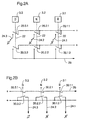
- FIGS. 2A and 2B show a technically alternative embodiment of the invention and 2B.
- a common mechanical Component for example a slide 12, as described, for generating the Signal "actuation of an actuator" is dispensed with and this Signal is generated by electrical means alone.
- FIG. 2A shows an embodiment in which the Signals when actuating the actuators 3.1 - 3.n NO 20.1.1-20.n.1 and 20.1.2 - 20.n.2 can be used.
- the one actuator 3.1-3.n are assigned normally open contacts 20.1.1 - 20.n.1 and 20.1.2 - 20.n.2 mechanically coupled to one another, for example via a rod 22.
- At Operating an actuator close the two together coupled NO contact.
- By closing the second with the first closer 20.1.1 - 20.n.1 coupled NO 20.1.2 - 20.n.2 will be an impulse to all Actuators common line 26 given.
- the signal on line 26 represents the state "actuating a Actuating element "without specifying which of the NO contacts or Actuators was actuated.
- Line 26 which is a parallel connection of the normally open contacts 20.3.2, 20.2.2 20.1.2 represents, replaced compared to that described in Figure 1A electromechanical solution, the slide device 12 with magnets, the comes into operative connection with the sensor 11 in the form of a contact.
- FIG. 2B shows an alternative electrical embodiment to that in FIG. 2A shown, with the same components as in Figures 2A and 2B are assigned the same reference numbers.
- the make contacts 20.1.1 - 20.n.1 and 20.1.2 - 20.n.2 are normally closed 30.1.1 - 30.n.1 and 30.1.2 - 30.n.2 used.
- a signal is delivered when the contact is opened, i.e. when an off pulse is given.
- Signals when opening are both the individual actuators as well as the common line "Actuation of an actuating element" assigned.
Landscapes
- Engineering & Computer Science (AREA)
- General Engineering & Computer Science (AREA)
- Mechanical Engineering (AREA)
- Control Of Transmission Device (AREA)
Applications Claiming Priority (2)
| Application Number | Priority Date | Filing Date | Title |
|---|---|---|---|
| DE19920001A DE19920001A1 (de) | 1999-05-03 | 1999-05-03 | Vorwahleinrichtung, insbesondere Tastschalteinrichtung |
| DE19920001 | 1999-05-03 |
Publications (3)
| Publication Number | Publication Date |
|---|---|
| EP1050698A2 true EP1050698A2 (fr) | 2000-11-08 |
| EP1050698A3 EP1050698A3 (fr) | 2002-08-14 |
| EP1050698B1 EP1050698B1 (fr) | 2004-01-21 |
Family
ID=7906605
Family Applications (1)
| Application Number | Title | Priority Date | Filing Date |
|---|---|---|---|
| EP00109394A Expired - Lifetime EP1050698B1 (fr) | 1999-05-03 | 2000-05-03 | Dispositif de sélection de la gamme à bouton de manoeuvre par pression pour transmission automatique |
Country Status (2)
| Country | Link |
|---|---|
| EP (1) | EP1050698B1 (fr) |
| DE (2) | DE19920001A1 (fr) |
Cited By (2)
| Publication number | Priority date | Publication date | Assignee | Title |
|---|---|---|---|---|
| WO2002014718A1 (fr) * | 2000-08-15 | 2002-02-21 | Voith Turbo Gmbh & Co. Kg | Dispositif de detection d'inclinaison et systeme pour le reglage d'une commande conducteur |
| EP1995496A1 (fr) * | 2007-05-21 | 2008-11-26 | Magneti Marelli Powertrain S.p.A. | Système de contrôle de bouton poussoir pour changement de vitesse servo-mécanique |
Families Citing this family (1)
| Publication number | Priority date | Publication date | Assignee | Title |
|---|---|---|---|---|
| DE10137902A1 (de) * | 2001-01-29 | 2002-08-22 | Voith Turbo Kg | Verfahren zur Erhöhung der Fahrsicherheit beim Betrieb von Fahrzeugen mit integriertem Automatgetriebe durch Signalisierung der Akzeptanz einer gewünschten Fahrzustandsänderung und System zur Steuerung einer Getriebebaueinheit |
Citations (2)
| Publication number | Priority date | Publication date | Assignee | Title |
|---|---|---|---|---|
| DE1194269B (de) | 1958-08-27 | 1965-06-03 | Renault | Elektrische Drucktastensteuerung fuer Fahrzeugwechselgetriebe |
| EP0615078A1 (fr) | 1993-03-09 | 1994-09-14 | MAGNETI MARELLI S.p.A. | Système pour détecter la position d'une commande manuelle en particulier un sélecteur d'une bôite de vitesse à servocommande d'un véhicule automobile |
Family Cites Families (3)
| Publication number | Priority date | Publication date | Assignee | Title |
|---|---|---|---|---|
| US4137824A (en) * | 1977-01-31 | 1979-02-06 | Scovill Manufacturing Company | Remote shifter for vehicle transmissions |
| JPH0217265A (ja) * | 1988-07-05 | 1990-01-22 | Iseki & Co Ltd | 押ボタン型電子変速機の制御装置 |
| JP3576718B2 (ja) * | 1996-09-26 | 2004-10-13 | 株式会社東海理化電機製作所 | スイッチ装置 |
-
1999
- 1999-05-03 DE DE19920001A patent/DE19920001A1/de not_active Ceased
-
2000
- 2000-05-03 DE DE50005062T patent/DE50005062D1/de not_active Expired - Lifetime
- 2000-05-03 EP EP00109394A patent/EP1050698B1/fr not_active Expired - Lifetime
Patent Citations (2)
| Publication number | Priority date | Publication date | Assignee | Title |
|---|---|---|---|---|
| DE1194269B (de) | 1958-08-27 | 1965-06-03 | Renault | Elektrische Drucktastensteuerung fuer Fahrzeugwechselgetriebe |
| EP0615078A1 (fr) | 1993-03-09 | 1994-09-14 | MAGNETI MARELLI S.p.A. | Système pour détecter la position d'une commande manuelle en particulier un sélecteur d'une bôite de vitesse à servocommande d'un véhicule automobile |
Cited By (2)
| Publication number | Priority date | Publication date | Assignee | Title |
|---|---|---|---|---|
| WO2002014718A1 (fr) * | 2000-08-15 | 2002-02-21 | Voith Turbo Gmbh & Co. Kg | Dispositif de detection d'inclinaison et systeme pour le reglage d'une commande conducteur |
| EP1995496A1 (fr) * | 2007-05-21 | 2008-11-26 | Magneti Marelli Powertrain S.p.A. | Système de contrôle de bouton poussoir pour changement de vitesse servo-mécanique |
Also Published As
| Publication number | Publication date |
|---|---|
| EP1050698A3 (fr) | 2002-08-14 |
| EP1050698B1 (fr) | 2004-01-21 |
| DE19920001A1 (de) | 2000-11-16 |
| DE50005062D1 (de) | 2004-02-26 |
Similar Documents
| Publication | Publication Date | Title |
|---|---|---|
| DE3203702A1 (de) | Betaetigungsvorrichtung fuer ein automatisches kraftfahrzeug-getriebe | |
| DE19959616A1 (de) | Steuereinrichtung für ein automatisch und manuell schaltbares Schaltgetriebe in einem Kraftfahrzeug | |
| EP1549866B1 (fr) | Unite d'entree de rapports de vitesse | |
| EP1238214A1 (fr) | Systeme de detection destine au dispositif de commande d'une boite de vitesses automatique | |
| EP1259969B1 (fr) | Dispositif de commutation de securite comprenant un premier et un second commutateur d'entree | |
| DE4337524C2 (de) | Feststellvorrichtung für einen Schalthebel | |
| DE102013007233B4 (de) | Elektrische Schalteinrichtung für ein Kraftfahrzeug | |
| EP1611376B1 (fr) | Changement de vitesses du type shift-by-wire avec position p | |
| DE4439751A1 (de) | Anordnung zur gegenseitigen Verriegelung von Leistungsschaltern | |
| EP1050698B1 (fr) | Dispositif de sélection de la gamme à bouton de manoeuvre par pression pour transmission automatique | |
| DE2928194C2 (de) | Weichenantrieb | |
| EP0817226A2 (fr) | Interrupteur à bascule | |
| DE10202803B4 (de) | Schaltvorrichtung zum Schalten einer elektronischen Komponente eines Kraftfahrzeugs beim Starten oder Stoppen eines Motors des Kraftfahrzeugs | |
| DE10032518C1 (de) | Mehrstufige elektrische Schaltvorrichtung | |
| EP0809266A2 (fr) | Appareil de commutation à basse tension | |
| EP1078822B1 (fr) | Clavier | |
| DE102008018383B3 (de) | Eingabeeinrichtung | |
| WO1997004252A1 (fr) | Dispositif de selection pour boite automatique de vitesses | |
| DE19611064C2 (de) | Scheibenwischerschaltung | |
| DE102007042129B4 (de) | Mehrfachbedienelement | |
| EP0878815A2 (fr) | Appareil de commutation électrique monostable | |
| DE29820233U1 (de) | Elektromotorischer Möbelantrieb | |
| DE4424285A1 (de) | Zweikanalige Zweihandschaltung für elektrische Antriebe | |
| EP1371880B1 (fr) | Dispositif de commande de boite de vitesses de véhicule et levier de passage de vitesses | |
| DE19948736A1 (de) | Schaltvorrichtung für das Getriebe eines Kraftfahrzeuges |
Legal Events
| Date | Code | Title | Description |
|---|---|---|---|
| PUAI | Public reference made under article 153(3) epc to a published international application that has entered the european phase |
Free format text: ORIGINAL CODE: 0009012 |
|
| AK | Designated contracting states |
Kind code of ref document: A2 Designated state(s): AT BE CH CY DE DK ES FI FR GB GR IE IT LI LU MC NL PT SE |
|
| AX | Request for extension of the european patent |
Free format text: AL;LT;LV;MK;RO;SI |
|
| PUAL | Search report despatched |
Free format text: ORIGINAL CODE: 0009013 |
|
| AK | Designated contracting states |
Kind code of ref document: A3 Designated state(s): AT BE CH CY DE DK ES FI FR GB GR IE IT LI LU MC NL PT SE |
|
| AX | Request for extension of the european patent |
Free format text: AL;LT;LV;MK;RO;SI |
|
| 17P | Request for examination filed |
Effective date: 20021111 |
|
| 17Q | First examination report despatched |
Effective date: 20030213 |
|
| AKX | Designation fees paid |
Designated state(s): DE FR GB |
|
| GRAP | Despatch of communication of intention to grant a patent |
Free format text: ORIGINAL CODE: EPIDOSNIGR1 |
|
| GRAS | Grant fee paid |
Free format text: ORIGINAL CODE: EPIDOSNIGR3 |
|
| GRAA | (expected) grant |
Free format text: ORIGINAL CODE: 0009210 |
|
| AK | Designated contracting states |
Kind code of ref document: B1 Designated state(s): DE FR GB |
|
| REG | Reference to a national code |
Ref country code: GB Ref legal event code: FG4D Free format text: NOT ENGLISH |
|
| GBT | Gb: translation of ep patent filed (gb section 77(6)(a)/1977) |
Effective date: 20040121 |
|
| REG | Reference to a national code |
Ref country code: IE Ref legal event code: FG4D Free format text: GERMAN |
|
| REF | Corresponds to: |
Ref document number: 50005062 Country of ref document: DE Date of ref document: 20040226 Kind code of ref document: P |
|
| REG | Reference to a national code |
Ref country code: IE Ref legal event code: FD4D |
|
| ET | Fr: translation filed | ||
| PLBE | No opposition filed within time limit |
Free format text: ORIGINAL CODE: 0009261 |
|
| STAA | Information on the status of an ep patent application or granted ep patent |
Free format text: STATUS: NO OPPOSITION FILED WITHIN TIME LIMIT |
|
| 26N | No opposition filed |
Effective date: 20041022 |
|
| REG | Reference to a national code |
Ref country code: FR Ref legal event code: PLFP Year of fee payment: 16 |
|
| PGFP | Annual fee paid to national office [announced via postgrant information from national office to epo] |
Ref country code: GB Payment date: 20150521 Year of fee payment: 16 |
|
| PGFP | Annual fee paid to national office [announced via postgrant information from national office to epo] |
Ref country code: FR Payment date: 20150521 Year of fee payment: 16 |
|
| GBPC | Gb: european patent ceased through non-payment of renewal fee |
Effective date: 20160503 |
|
| REG | Reference to a national code |
Ref country code: FR Ref legal event code: ST Effective date: 20170131 |
|
| PG25 | Lapsed in a contracting state [announced via postgrant information from national office to epo] |
Ref country code: FR Free format text: LAPSE BECAUSE OF NON-PAYMENT OF DUE FEES Effective date: 20160531 |
|
| PG25 | Lapsed in a contracting state [announced via postgrant information from national office to epo] |
Ref country code: GB Free format text: LAPSE BECAUSE OF NON-PAYMENT OF DUE FEES Effective date: 20160503 |
|
| PGFP | Annual fee paid to national office [announced via postgrant information from national office to epo] |
Ref country code: DE Payment date: 20190521 Year of fee payment: 20 |
|
| REG | Reference to a national code |
Ref country code: DE Ref legal event code: R071 Ref document number: 50005062 Country of ref document: DE |