EP1051800B1 - Procede de reglage optimal en termes de puissance et de rendement de machine synchrones - Google Patents
Procede de reglage optimal en termes de puissance et de rendement de machine synchrones Download PDFInfo
- Publication number
- EP1051800B1 EP1051800B1 EP99960816A EP99960816A EP1051800B1 EP 1051800 B1 EP1051800 B1 EP 1051800B1 EP 99960816 A EP99960816 A EP 99960816A EP 99960816 A EP99960816 A EP 99960816A EP 1051800 B1 EP1051800 B1 EP 1051800B1
- Authority
- EP
- European Patent Office
- Prior art keywords
- generator
- phase
- current
- control
- voltage
- Prior art date
- Legal status (The legal status is an assumption and is not a legal conclusion. Google has not performed a legal analysis and makes no representation as to the accuracy of the status listed.)
- Expired - Lifetime
Links
- 238000000034 method Methods 0.000 title claims description 35
- 230000001360 synchronised effect Effects 0.000 title claims description 8
- 238000004804 winding Methods 0.000 claims description 13
- 230000002829 reductive effect Effects 0.000 claims description 6
- 230000005284 excitation Effects 0.000 description 22
- 230000008901 benefit Effects 0.000 description 5
- 210000000078 claw Anatomy 0.000 description 5
- 230000001276 controlling effect Effects 0.000 description 3
- 230000001419 dependent effect Effects 0.000 description 3
- 101150084044 P gene Proteins 0.000 description 2
- 238000001514 detection method Methods 0.000 description 2
- 230000002349 favourable effect Effects 0.000 description 2
- 230000036961 partial effect Effects 0.000 description 2
- 230000009467 reduction Effects 0.000 description 2
- 230000003313 weakening effect Effects 0.000 description 2
- 101100129500 Caenorhabditis elegans max-2 gene Proteins 0.000 description 1
- 230000002730 additional effect Effects 0.000 description 1
- 239000003990 capacitor Substances 0.000 description 1
- 238000002485 combustion reaction Methods 0.000 description 1
- 230000008878 coupling Effects 0.000 description 1
- 238000010168 coupling process Methods 0.000 description 1
- 238000005859 coupling reaction Methods 0.000 description 1
- 230000003247 decreasing effect Effects 0.000 description 1
- 238000010438 heat treatment Methods 0.000 description 1
- 230000006872 improvement Effects 0.000 description 1
- 230000000670 limiting effect Effects 0.000 description 1
- 238000004519 manufacturing process Methods 0.000 description 1
- 230000003287 optical effect Effects 0.000 description 1
- 230000003071 parasitic effect Effects 0.000 description 1
- 238000010248 power generation Methods 0.000 description 1
- 230000008569 process Effects 0.000 description 1
- 230000001105 regulatory effect Effects 0.000 description 1
Images

Classifications
-
- H—ELECTRICITY
- H02—GENERATION; CONVERSION OR DISTRIBUTION OF ELECTRIC POWER
- H02P—CONTROL OR REGULATION OF ELECTRIC MOTORS, ELECTRIC GENERATORS OR DYNAMO-ELECTRIC CONVERTERS; CONTROLLING TRANSFORMERS, REACTORS OR CHOKE COILS
- H02P9/00—Arrangements for controlling electric generators for the purpose of obtaining a desired output
- H02P9/48—Arrangements for obtaining a constant output value at varying speed of the generator, e.g. on vehicle
-
- H—ELECTRICITY
- H02—GENERATION; CONVERSION OR DISTRIBUTION OF ELECTRIC POWER
- H02P—CONTROL OR REGULATION OF ELECTRIC MOTORS, ELECTRIC GENERATORS OR DYNAMO-ELECTRIC CONVERTERS; CONTROLLING TRANSFORMERS, REACTORS OR CHOKE COILS
- H02P9/00—Arrangements for controlling electric generators for the purpose of obtaining a desired output
- H02P9/14—Arrangements for controlling electric generators for the purpose of obtaining a desired output by variation of field
- H02P9/26—Arrangements for controlling electric generators for the purpose of obtaining a desired output by variation of field using discharge tubes or semiconductor devices
- H02P9/30—Arrangements for controlling electric generators for the purpose of obtaining a desired output by variation of field using discharge tubes or semiconductor devices using semiconductor devices
Definitions
- FIG. 1 shows such an arrangement.
- the generator is controlled by the excitation current so that the output voltage U B of the generator regardless of the speed and, within the performance of the generator, regardless of the load adjusts to the desired value.
- the power output begins only after reaching a certain speed, the so-called Angehcardiere. At speeds less than the starting speed, the generator voltage is less than the battery voltage. In this case, no power can be fed into the electrical system via the B6 rectifier bridge.
- Another starting point for increasing performance is the variation of the number of stator turns.
- An increase in the number of stator turns leads to a reduction in the starting speed and to an increase in the output power in the low speed range.
- the output power in the middle and high speed range is significantly reduced.
- a reduction of the stator winding number leads to an increase in power in the high speed range, at the same time, however, the power is reduced in the lower speed range and increases the Angehcard. For this reason, a variation of the stator winding number does not lead to the goal of an increase in power over a wide speed range.
- a significant disadvantage of the rectification of the 3-phase generator currents by means of a passive B6 bridge is that amount and phase of the phase current or the Polradwinkel are not used as a control variable for the generator control.
- the machine can therefore not be optimally performed in all operating points with respect to output power, efficiency and control dynamics.
- the U.S. Patent 5,648,705 or the EP 0 762 596 A1 describes a method in which the power increase in the lower speed range is addressed by changing the angle between stator current and Polradschreib. An elaborated rule concept is not shown. If maximum output power is not required in the lower speed range, then the 3-phase current of the generator is set to the desired output voltage by means of a passive diode bridge and sole regulation of the exciter current. For the passive diode bridge, the parasitic diodes of the MOSFET switches of the converter circuit are used. However, it is not dealt with the regulation in the middle and higher speed range. A performance and efficiency-optimal machine guidance in the middle and higher speed range at full and part load is therefore not achieved.
- Control methods for generators are known in which on the one hand, the excitation current is controlled and on the other hand, the generator current is influenced by means of a block inverter bridge in a predetermined manner. Part of the control procedure also relates to influencing the torque exerted by the generator in a desired manner.
- the known control arrangement comprises, in addition to a conventional regulator for the excitation current, a microprocessor which is connected on the one hand to the conventional regulator and, on the other hand, is connected to the block inverter bridge of the generator arrangement and supplies this drive signal.
- the claims show methods which can freely select for each speed point and each desired generator power, the excitation current and the phase current in terms of magnitude and phase. This results in the possibility of selecting the most suitable for the current needs from all possible operating conditions of the machine or of the generator and adjust the most favorable operating point according to the requirements.
- the desired output power not only affects the setpoint value of the excitation current, but directly affects all control parameters of the machine that are relevant to the machine control.
- the method and apparatus for controlling a generator according to the invention have the advantage that both the available output power and the efficiency of the generator are substantially increased in a wide speed range compared to a generator with passive diode rectification.
- the advantages are achieved by a process consisting of a total of four different control ranges for controlling the generator.
- One of the four control ranges is selected according to the given requirements and constraints, such as the desired output power and given generator speed. In this way, compared to the operation with passive rectification a much cheaper machine management is possible, leading to a Increasing the available output power, the efficiency and the control dynamics leads.
- the claimed methods are advantageously applicable both to synchronous full pole and synchronous pole machines and to generators based on similar operating principles, for example claw pole generators.
- the string windings of the machine can be connected in both star and delta connection.
- a method is illustrated using the example of an idealized synchronous kingpinning machine. For machines having similar functional principles or not negligible additional effects, e.g. have a pronounced magnetically nonlinear behavior, the described method can be applied with the help of similar considerations.
- FIG. 1 are the essential for the understanding of the invention essential components of a generator G shown with passive rectification.
- FIG. 1 shows the procedure common in motor vehicles today to generate direct current with the aid of a claw pole generator and a diode bridge.
- L E denotes the inductance of the excitation winding and I E den Excitation current.
- L s the stator or -strand inductances are designated.
- Up symbolizes the Polradschreib and R the resistance of the windings.
- the diodes of the diode bridge are denoted mi D1 to D6 and U B is the vehicle electrical system voltage or battery voltage.
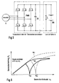
- FIG. 2 The basic arrangement of the overall system is in FIG. 2 shown.
- the generator leads via pulse inverter elements PWR to a DC link capacitor ZK and the battery BA.
- a device VO determines the generator speed n G and the rotor position.
- the individual controllers are labeled ER (excitation current regulator), SR (stator current regulator), ÜR (superordinate regulator) and SpR (voltage regulator).
- ER excitation current regulator
- SR stator current regulator
- ÜR superordinate regulator
- SpR voltage regulator
- the desired nominal power of the generator P soll is determined by a voltage regulator, for example a PI controller, with the aid of the control deviation between the setpoint and the actual value of the battery voltage U Bset -U Bist .
- a device for position and speed detection determines the rotor position and the generator speed. The method for position and speed detection can be based for example on optical, magnetic or mechanical principles. Furthermore, there are also sensorless methods which determine the position of the rotor and its speed from the terminal values of the machine. These methods are known and will therefore not be described further here.
- Input variables for the higher-level controller are the desired generator power P setpoint , the speed n G and the intermediate circuit voltage U Bist .
- the higher-level controller optionally selects one of four control ranges.
- the setpoint values of the higher-level controller are, as defined in Fig. 2, the amount Is set and the phase position ⁇ setpoint of the phase current or the longitudinal and transverse components of the phase current I dsoll , I qsoll , as well as the setpoint value of the excitation current I ESoll .
- Input variables of the stator current regulator are the rotor position and the generator speed n G , the setpoint values of the phase currents and the measured phase currents I List1 and I List2 . From the measured two phase currents, the phase currents of the generator can be determined by calculation. Alternatively, all three phase currents or two or three phase currents can be measured directly.
- the stator current controller controls the 6 switches of the pulse-controlled inverter ( FIG. 5 ) in an appropriate manner to impress the strand current in magnitude and phase.
- the switches of the pulse inverter can, for example, as in FIG. 5 represented as MOSFET transistors are executed.
- MOSFET transistors are executed.
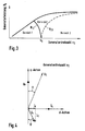
- the basic course of the control ranges 1-3 is in FIG. 3 as a function of the output power P GEN and the generator speed n G.
- FIG. 6 It is shown how the performance of the generator varies with variation of the stator winding number. If the stator winding number is reduced from w1 to w2, the power increases at high speeds. The boundary lines N 12 and N 23 are shifted towards higher speeds. However, the achievable in the very low speed range maximum output power remains constant. It runs in the area 1 regardless of the number of stator turns on the same line.
- the control ranges 1-3 also represent areas with different efficiency. By changing the stator winding number, therefore, both the power and the efficiency behavior of the load characteristic can be adjusted. For example, can be achieved in this way that the idle speed of the vehicle is covered by the efficiency-optimal control range 1.
- the control range 1 covers the lower speed range of the generator.
- the phase voltage U S is therefore always smaller than the maximum value U max that can be set by the pulse inverter.
- the phase angle and the amount of phase currents can therefore be set without limitation to the maximum output power of the machine.
- the maximum possible phase current is limited only by the heating of the machine. At a constant phase current I S in the control range 1, the maximum output power of the machine increases proportionally with the speed.
- phase position of the phase currents can no longer be adjusted by the pulse inverter according to the strategy of the control range 1.
- the phase voltage exceeds the maximum value of the voltage setting range U max of the pulse-controlled inverter given by the intermediate circuit voltage U Bist .
- control range 2 in which the strand tension must be limited to its maximum possible value by a suitable machine guide.
- the phase angle of the Phase current is chosen so that the voltage setting range U max of the pulse-controlled inverter is not exceeded by a weakening of the air gap field.
- the desired generator power can be set by varying the rotor angle ⁇ .
- a specific rotor angle ⁇ ⁇ (P soll ) can be set, within the framework of the generator's capacity.
- the machine guide for the control area 3 is completely defined.
- control structures described in the control area 1-3 cover all normal operating conditions of the machine.
- control range 4 described below serves on the one hand to ensure a high control dynamics under extreme load drops. On the other hand, this control function provides an additional safety function against overvoltages.
- U Bist exceeds an adjustable overvoltage threshold
- normal PWM inverter operation is exited and the 3-phase outputs of the generator are short-circuited with the aid of the switches of the pulse-controlled inverter. This reduces the overvoltage very quickly.
- the exciter current of the machine is reduced, for example by rapid de-excitation. If the output voltage reaches an adjustable undervoltage threshold below the Setpoint of the output voltage U Bsetpoint , the machine is again guided according to control range 1-3.
- the higher-level controller has inputs P soll. n G , U b and the outputs I E , Id and Iq, or I s and ⁇ .
- This dependency can be mapped using a multi-dimensional table.
- This table contains the off-line calculated equations of the higher order controller (control range 1- 4)
Landscapes
- Engineering & Computer Science (AREA)
- Power Engineering (AREA)
- Control Of Eletrric Generators (AREA)
Claims (6)
- Procédé de régulation à optimisation de la puissance et du rendement d'un générateur qui présente un bobinage d'excitateur et auquel des ponts convertisseurs sont associés, dans lequel le courant d'excitateur (IE) qui traverse le bobinage d'excitateur est régulé de telle sorte que la tension de sortie délivrée par le générateur atteigne un niveau prédéterminé et qu'en supplément les courants de barres du générateur soient régulés, avec formation d'au moins trois plages de régulation dans lesquelles la régulation du courant d'excitateur et des courants de barres du générateur s'effectue suivant des critères différents,
caractérisé en ce que
dans une première plage de régulation, le courant d'excitateur est placé à sa valeur maximale possible, la tension de barre étant inférieure à la valeur maximale qui peut être établie par l'onduleur pulsé,
en ce que dans une deuxième plage de régulation, le courant d'excitateur est également fixé à sa valeur maximale mais le déphasage du courant de barre est sélectionné de telle sorte que la tension de barre prenne la valeur maximale possible et
en ce que dans une troisième plage de régulation, le générateur est utilisé de telle sorte que le courant de barre et la tension de barre soient en phase, le facteur de puissance étant ainsi cos ϕ = 1, et que le courant d'excitateur soit régulé de manière à obtenir un angle ϕ = 0. - Procédé selon la revendication 1, caractérisé en ce que le générateur est une machine synchrone.
- Procédé selon la revendication 1, caractérisé en ce que les trois plages de régulation sont formées en fonction de la puissance de sortie (PGen) du générateur et/ou de la vitesse de rotation (nG) du générateur.
- Procédé selon les revendications 1 ou 2, caractérisé en ce que la régulation s'effectue de telle sorte que le courant d'excitateur et le ou les courants de barres puissent être sélectionnés librement en termes de valeur et de phase pour chaque vitesse de rotation du générateur et chaque puissance souhaitée du générateur.
- Procédé selon l'une des revendications précédentes, caractérisé en ce que dans une quatrième plage de régulation, après le dépassement d'un seuil de tension prédéterminé, les bobinages du générateur sont mis en court-circuit par commande appropriée des éléments convertisseurs et le courant d'excitateur est réduit.
- Procédé selon l'une des revendications précédentes, caractérisé en ce que les grandeurs nécessaires pour la régulation, à savoir la valeur de consigne du courant d'excitateur IEsoll, la composante longitudinale et la composante transversale du courant de barre Idsoll et Iqsollt sont déterminées à l'aide de tableaux multidimensionnels.
Applications Claiming Priority (3)
| Application Number | Priority Date | Filing Date | Title |
|---|---|---|---|
| DE19849889 | 1998-10-29 | ||
| DE19849889A DE19849889A1 (de) | 1998-10-29 | 1998-10-29 | Verfahren zur leistungs- und wirkungsgradoptimierten Regelung von Synchronmaschinen |
| PCT/DE1999/003416 WO2000027023A1 (fr) | 1998-10-29 | 1999-10-27 | Procede de reglage optimal en termes de puissance et de rendement de machine synchrones |
Publications (2)
| Publication Number | Publication Date |
|---|---|
| EP1051800A1 EP1051800A1 (fr) | 2000-11-15 |
| EP1051800B1 true EP1051800B1 (fr) | 2012-09-05 |
Family
ID=7886057
Family Applications (1)
| Application Number | Title | Priority Date | Filing Date |
|---|---|---|---|
| EP99960816A Expired - Lifetime EP1051800B1 (fr) | 1998-10-29 | 1999-10-27 | Procede de reglage optimal en termes de puissance et de rendement de machine synchrones |
Country Status (11)
| Country | Link |
|---|---|
| US (1) | US6359421B1 (fr) |
| EP (1) | EP1051800B1 (fr) |
| JP (1) | JP2002530040A (fr) |
| KR (1) | KR100766283B1 (fr) |
| CN (1) | CN1200507C (fr) |
| BR (1) | BR9907074A (fr) |
| DE (1) | DE19849889A1 (fr) |
| HU (1) | HU223993B1 (fr) |
| PL (1) | PL198697B1 (fr) |
| RU (1) | RU2235412C2 (fr) |
| WO (1) | WO2000027023A1 (fr) |
Families Citing this family (44)
| Publication number | Priority date | Publication date | Assignee | Title |
|---|---|---|---|---|
| DE10036099A1 (de) * | 2000-07-25 | 2002-02-14 | Bosch Gmbh Robert | Verfahren zur Regelung einer elektrischen Maschine mit Pulswechselrichter |
| DE10036869A1 (de) * | 2000-07-28 | 2002-02-21 | Bosch Gmbh Robert | Verfahren zur Schätzung der Polradlage an einer Klauenpolmaschine |
| DE10044181A1 (de) * | 2000-09-07 | 2002-04-04 | Bosch Gmbh Robert | Reglerstruktur für elektrische Maschinen |
| JP3545693B2 (ja) | 2000-11-01 | 2004-07-21 | 三菱電機株式会社 | クローポール同期機の制御方法 |
| DE10106944B4 (de) * | 2001-02-15 | 2010-08-05 | Robert Bosch Gmbh | Verfahren zur Temperaturregelung einer elektrischen Maschine |
| DE10110939B4 (de) * | 2001-03-07 | 2004-07-08 | Mühlbauer Ag | Verfahren und Vorrichtung zum Heißpressverbinden eines Chipmoduls mit einem Trägersubstrat |
| DE10130339A1 (de) * | 2001-06-26 | 2003-01-02 | Abb Research Ltd | Verfahren und Vorrichtung zur Verbesserung des Nutzungsgrades und der Zuverlässigkeit einer Kraftanlage |
| US6703718B2 (en) * | 2001-10-12 | 2004-03-09 | David Gregory Calley | Wind turbine controller |
| JP4236870B2 (ja) * | 2002-06-03 | 2009-03-11 | 三菱電機株式会社 | 車両用回転電機の制御装置および制御法 |
| AU2003268751A1 (en) * | 2002-10-11 | 2004-05-04 | Mitsuba Corporation | Control method of generator |
| US6803748B2 (en) * | 2003-02-03 | 2004-10-12 | Delphi Technologies, Inc. | System and method for controlling load dump voltage of a synchronous machine |
| JP4113848B2 (ja) | 2004-02-18 | 2008-07-09 | 三菱電機株式会社 | 電動発電機の制御装置 |
| US8018081B2 (en) * | 2005-07-15 | 2011-09-13 | Southwest Windpower, Inc. | Wind turbine and method of manufacture |
| FR2892077B1 (fr) * | 2005-10-17 | 2009-05-15 | Peugeot Citroen Automobiles Sa | Circuit d'alimentation en energie electrique d'un vehicule automobile |
| FR2897656B1 (fr) * | 2006-02-23 | 2011-05-20 | Renault Sas | Procede et systeme de commande d'une bougie de prechauffage, a alimentation a basse tension electrique, d'un melange air/carburant de moteur diesel |
| US7439713B2 (en) * | 2006-09-20 | 2008-10-21 | Pratt & Whitney Canada Corp. | Modulation control of power generation system |
| US7623331B2 (en) * | 2006-10-06 | 2009-11-24 | Remy International, Inc. | Method and system for improving voltage regulator accuracy in vehicle alternators |
| FI119898B (fi) | 2007-02-14 | 2009-04-30 | Konecranes Oyj | Generaattorikokoonpano |
| WO2009064440A2 (fr) | 2007-11-13 | 2009-05-22 | Emerson Climate Technologies, Inc. | Module de détection triphasé |
| DE102008042352A1 (de) * | 2008-09-25 | 2010-04-08 | Robert Bosch Gmbh | Ansteuerung eines Synchrongleichrichters |
| DE102008042931A1 (de) | 2008-10-17 | 2010-04-22 | Robert Bosch Gmbh | Verfahren und Vorrichtung zur feldorientierten Regelung einer Synchronmaschine |
| FR2948512A1 (fr) * | 2009-07-24 | 2011-01-28 | Peugeot Citroen Automobiles Sa | Procede de commande d'un dispositif d'alimentation, dispositif d'alimentation et support d'enregistrement pour ce procede |
| DE102009045351A1 (de) | 2009-10-06 | 2011-04-14 | Robert Bosch Gmbh | Verfahren zum Betreiben eines Antriebsaggregats sowie Antriebsaggregat |
| TWI398742B (zh) * | 2009-12-02 | 2013-06-11 | Univ Nat Cheng Kung | 應用田口方法以及模糊推論決定發電機最佳參數之方法 |
| DE102010043095A1 (de) * | 2010-10-29 | 2012-05-03 | Robert Bosch Gmbh | Verfahren zur Reduzierung einer Spannungswelligkeit aufgrund Drehungleichförmigkeit eines von einer Brennkraftmaschine angetriebenen Generators |
| US20120126758A1 (en) * | 2010-11-19 | 2012-05-24 | Hamilton Sundstrand Corporation | High voltage dc power generation |
| DE102010062338A1 (de) * | 2010-12-02 | 2012-06-06 | Robert Bosch Gmbh | Verfahren und Vorrichtung zum Betrieb einer fremderregten elektrischen Maschine |
| FR2971648B1 (fr) * | 2011-02-16 | 2016-10-14 | Moteurs Leroy-Somer | Ensemble fonctionnant a regime variable, comportant un alternateur synchrone a rotor bobine et un convertisseur |
| DE102011076999A1 (de) | 2011-05-26 | 2012-11-29 | Robert Bosch Gmbh | Verfahren zum Betreiben einer elektrischen Maschine in einem Kraftfahrzeug |
| FR2979765B1 (fr) * | 2011-09-01 | 2015-06-26 | Leroy Somer Moteurs | Procede de regulation d'un groupe electrogene |
| DE102012204751B4 (de) | 2012-03-26 | 2018-12-20 | Robert Bosch Gmbh | Verfahren zur Überprüfung einer Erregerstrommessung einer Synchronmaschine im Generatorbetrieb |
| FR3004603B1 (fr) * | 2013-04-10 | 2015-07-03 | Valeo Systemes De Controle Moteur | Systeme d’entrainement rotatif, procede de commande d’un onduleur et programme d’ordinateur associe |
| DE102013208968B4 (de) | 2013-05-15 | 2026-03-26 | Seg Automotive Germany Gmbh | Kraftfahrzeugbordnetz mit aktivem Brückengleichrichter und Überspannungsschutz bei Lastabwurf, Gleichrichteranordnung, zugehöriges Betriebsverfahren und Mittel zu dessen Implementierung |
| US20150249417A1 (en) * | 2013-12-30 | 2015-09-03 | Rolls-Royce Corporation | Synchronous generator controller based on flux optimizer |
| DE102014102352A1 (de) * | 2014-02-24 | 2015-08-27 | Ge Energy Power Conversion Technology Limited | Batteriespeichersystem mit Störlichtbogenschutz, Energieumwandlungssystem und Schutzverfahren |
| DE102015009490B4 (de) * | 2015-07-22 | 2020-04-02 | Audi Ag | Spannungsstabilisierung eines Kraftfahrzeug-Generators |
| ES2890834T3 (es) | 2016-06-28 | 2022-01-24 | Martin Special Technics Gmbh | Sistema de generación de energía con un generador y procedimiento de funcionamiento de dicho sistema de generación de energía |
| CN107154762B (zh) * | 2017-05-17 | 2019-04-23 | 苏州半唐电子有限公司 | 一种无传感永磁同步电机最优效率跟踪的控制方法 |
| RU2645387C1 (ru) * | 2017-05-30 | 2018-02-21 | Федеральное государственное бюджетное образовательное учреждение высшего образования "Государственный университет морского и речного флота имени адмирала С.О. Макарова" | Способ распределения нагрузки между параллельно работающими судовыми дизель-генераторными агрегатами |
| FR3083025B1 (fr) * | 2018-06-20 | 2020-07-10 | Valeo Equipements Electriques Moteur | Systeme de regulation ameliore pour une machine electrique tournante |
| CA3119273A1 (fr) | 2018-11-09 | 2020-05-14 | Iocurrents, Inc. | Prediction, planification et optimisation basees sur l'apprentissage automatique du temps de voyage, du cout de voyage et/ou de l'emission de polluants pendant la navigation |
| RU2704313C1 (ru) * | 2018-11-26 | 2019-10-28 | Федеральное государственное бюджетное образовательное учреждение высшего образования "Казанский государственный энергетический университет" (ФГБОУ ВО "КГЭУ") | Система форсировки возбуждения автономного синхронного генератора, входящего в электротехнический комплекс, с использованием накопителей энергии на основе аккумуляторных батарей и суперконденсаторов большой мощности |
| FR3092209A1 (fr) * | 2019-01-29 | 2020-07-31 | Psa Automobiles Sa | Procede et systeme de gestion de l’alimentation d’un reseau de bord d’un vehicule automobile |
| RU2721477C1 (ru) * | 2019-12-03 | 2020-05-19 | федеральное государственное бюджетное образовательное учреждение высшего образования "Нижегородский государственный технический университет им. Р.Е. Алексеева" (НГТУ) | Система управления накопителями электрической энергии для расширения области допустимых режимов генерирующих установок источников распределенной генерации при провалах напряжения |
Family Cites Families (10)
| Publication number | Priority date | Publication date | Assignee | Title |
|---|---|---|---|---|
| US3908130A (en) * | 1974-08-30 | 1975-09-23 | Gen Electric | Starter-generator utilizing phase controlled rectifiers to drive a dynamoelectric machine as a brushless motor in the starting mode to increase the torque output of the machine through phase angle control by reducing the machine counter EMF |
| DE3013473A1 (de) * | 1980-04-08 | 1981-10-15 | Braun Ag, 6000 Frankfurt | Verfahren und anordnung zur steuerung und regelung eines motors mit permanentmagnetischem laeufer |
| US4816736A (en) * | 1987-03-12 | 1989-03-28 | Globe-Union Inc. | Polyphase alternator and dual voltage battery charging system for multiple voltage loads |
| JP2569360B2 (ja) | 1988-11-25 | 1997-01-08 | 多摩川精機株式会社 | 発電機 |
| US5663631A (en) * | 1994-07-19 | 1997-09-02 | Nippondenso Co., Ltd. | Generator with circuitry for controlling power generation based on rotational speed |
| DE69530828T2 (de) | 1994-12-16 | 2004-01-22 | Delphi Technologies, Inc., Troy | Drehmoment- und Ausgang-Steuerung einer Brennkraftslichtmaschine |
| US5648705A (en) | 1995-09-05 | 1997-07-15 | Ford Motor Company | Motor vehicle alternator and methods of operation |
| DE19733212A1 (de) | 1997-08-01 | 1999-02-04 | Bosch Gmbh Robert | Verfahren zur Regelung eines von einer Brennkraftmaschine antreibbaren Generators |
| DE19733221A1 (de) * | 1997-08-01 | 1999-02-04 | Bosch Gmbh Robert | Verfahren zur Regelung eines Generators |
| US6181112B1 (en) * | 1998-12-10 | 2001-01-30 | Hamilton Sundstrand Corporation | Apparatus and method for limiting generator peak voltage |
-
1998
- 1998-10-29 DE DE19849889A patent/DE19849889A1/de not_active Ceased
-
1999
- 1999-10-27 CN CNB998019615A patent/CN1200507C/zh not_active Expired - Fee Related
- 1999-10-27 PL PL341570A patent/PL198697B1/pl unknown
- 1999-10-27 HU HU0101221A patent/HU223993B1/hu not_active IP Right Cessation
- 1999-10-27 RU RU2000120181/09A patent/RU2235412C2/ru not_active IP Right Cessation
- 1999-10-27 EP EP99960816A patent/EP1051800B1/fr not_active Expired - Lifetime
- 1999-10-27 JP JP2000580294A patent/JP2002530040A/ja active Pending
- 1999-10-27 WO PCT/DE1999/003416 patent/WO2000027023A1/fr not_active Ceased
- 1999-10-27 KR KR1020007007223A patent/KR100766283B1/ko not_active Expired - Fee Related
- 1999-10-27 US US09/582,593 patent/US6359421B1/en not_active Expired - Fee Related
- 1999-10-27 BR BR9907074-0A patent/BR9907074A/pt not_active IP Right Cessation
Also Published As
| Publication number | Publication date |
|---|---|
| HU223993B1 (hu) | 2005-04-28 |
| US6359421B1 (en) | 2002-03-19 |
| CN1287710A (zh) | 2001-03-14 |
| JP2002530040A (ja) | 2002-09-10 |
| HUP0101221A3 (en) | 2002-10-28 |
| PL198697B1 (pl) | 2008-07-31 |
| PL341570A1 (en) | 2001-04-23 |
| KR20010033700A (ko) | 2001-04-25 |
| KR100766283B1 (ko) | 2007-10-11 |
| BR9907074A (pt) | 2000-10-17 |
| CN1200507C (zh) | 2005-05-04 |
| WO2000027023A1 (fr) | 2000-05-11 |
| DE19849889A1 (de) | 2000-05-04 |
| HUP0101221A2 (hu) | 2001-08-28 |
| EP1051800A1 (fr) | 2000-11-15 |
| RU2235412C2 (ru) | 2004-08-27 |
Similar Documents
| Publication | Publication Date | Title |
|---|---|---|
| EP1051800B1 (fr) | Procede de reglage optimal en termes de puissance et de rendement de machine synchrones | |
| EP0875089B1 (fr) | Systeme d'alimentation electrique | |
| DE10206955B4 (de) | Lenksteuergerät | |
| EP0999953B1 (fr) | Procede et appareil pour reguler un generateur pouvant etre entraine par un moteur a combustion interne | |
| DE102015117813B4 (de) | Steuerungseinheit und Steuerungsverfahren für rotierende elektrische Maschine | |
| EP1305876B1 (fr) | Procede pour reguler une machine electrique au moyen d'un onduleur pulse | |
| EP0929927B1 (fr) | Procede pour reguler un generateur | |
| EP3676953A1 (fr) | Procédé servant à commander un générateur synchrone polyphasé à excitation séparée | |
| DE112016000455T5 (de) | Steuerungsgerät für eine rotierende elektrische Maschine | |
| DE10219822A1 (de) | Verfahren und Vorrichtung zur sensorreduzierten Regelung einer permanentmagneterregten Synchronmaschine | |
| EP0772904B1 (fr) | Dispositif d'alimentation en courant avec deux tensions de sortie | |
| EP3695509B1 (fr) | Procédé pour effectuer un changement entre une commande par bloc et une commande par mli d'une machine électrique | |
| DE102010019151B4 (de) | Verfahren und Vorrichtung zur Energieübertragung in einem Kraftfahrzeug | |
| EP3264587B1 (fr) | Système de production d'énergie comprenant un générateur et son procédé de fonctionnement | |
| WO2012107330A2 (fr) | Procédé pour régler un couple réel, délivré par une machine électrique dans un véhicule automobile, sur un couple de consigne | |
| WO2018029309A1 (fr) | Procédé pour faire fonctionner un convertisseur et convertisseur fonctionnant de manière correspondante | |
| EP3695508B1 (fr) | Procédé pour faire fonctionner une machine électrique | |
| EP3172831A1 (fr) | Procédé de commande d'au moins une machine électrique pouvant fonctionner en générateur et moyen pour mettre en oeuvre celui-ci | |
| EP3685504B1 (fr) | Procédé pour faire fonctionner une machine électrique à excitation séparée | |
| EP3476038A1 (fr) | Procédé de régulation d'une machine synchrone et dispositif de régulation destiné à une machine synchrone | |
| EP3685503B1 (fr) | Procédé de détermination d'un couple maximal réglable d'une machine électrique | |
| DE102004059609A1 (de) | Steuereinheit für eine rotierende Elektromaschine für ein Fahrzeug | |
| DE102017212778A1 (de) | Ansteuerung einer 6-phasigen permanenterregten Synchronmaschine im Fehlerfall eines Leistungsschalterkurzschlusses | |
| DE102013226210A1 (de) | Leistungsversorgungsvorrichtung und Verfahren zum Steuern der Leistungsversorgungsvorrichtung | |
| DE102007006154A1 (de) | Motoransteuervorrichtung |
Legal Events
| Date | Code | Title | Description |
|---|---|---|---|
| PUAI | Public reference made under article 153(3) epc to a published international application that has entered the european phase |
Free format text: ORIGINAL CODE: 0009012 |
|
| AK | Designated contracting states |
Kind code of ref document: A1 Designated state(s): AT BE CH CY DE DK ES FI FR GB GR IE IT LI LU MC NL PT SE |
|
| 17P | Request for examination filed |
Effective date: 20001113 |
|
| RBV | Designated contracting states (corrected) |
Designated state(s): DE ES FR GB IT SE |
|
| 17Q | First examination report despatched |
Effective date: 20100128 |
|
| GRAP | Despatch of communication of intention to grant a patent |
Free format text: ORIGINAL CODE: EPIDOSNIGR1 |
|
| GRAS | Grant fee paid |
Free format text: ORIGINAL CODE: EPIDOSNIGR3 |
|
| GRAA | (expected) grant |
Free format text: ORIGINAL CODE: 0009210 |
|
| AK | Designated contracting states |
Kind code of ref document: B1 Designated state(s): DE ES FR GB IT SE |
|
| REG | Reference to a national code |
Ref country code: GB Ref legal event code: FG4D Free format text: NOT ENGLISH |
|
| REG | Reference to a national code |
Ref country code: DE Ref legal event code: R096 Ref document number: 59915351 Country of ref document: DE Effective date: 20121031 |
|
| PG25 | Lapsed in a contracting state [announced via postgrant information from national office to epo] |
Ref country code: SE Free format text: LAPSE BECAUSE OF FAILURE TO SUBMIT A TRANSLATION OF THE DESCRIPTION OR TO PAY THE FEE WITHIN THE PRESCRIBED TIME-LIMIT Effective date: 20120905 |
|
| PG25 | Lapsed in a contracting state [announced via postgrant information from national office to epo] |
Ref country code: ES Free format text: LAPSE BECAUSE OF FAILURE TO SUBMIT A TRANSLATION OF THE DESCRIPTION OR TO PAY THE FEE WITHIN THE PRESCRIBED TIME-LIMIT Effective date: 20121216 |
|
| PGFP | Annual fee paid to national office [announced via postgrant information from national office to epo] |
Ref country code: DE Payment date: 20121217 Year of fee payment: 14 Ref country code: FR Payment date: 20130123 Year of fee payment: 14 |
|
| PLBE | No opposition filed within time limit |
Free format text: ORIGINAL CODE: 0009261 |
|
| STAA | Information on the status of an ep patent application or granted ep patent |
Free format text: STATUS: NO OPPOSITION FILED WITHIN TIME LIMIT |
|
| 26N | No opposition filed |
Effective date: 20130606 |
|
| GBPC | Gb: european patent ceased through non-payment of renewal fee |
Effective date: 20121205 |
|
| PG25 | Lapsed in a contracting state [announced via postgrant information from national office to epo] |
Ref country code: IT Free format text: LAPSE BECAUSE OF FAILURE TO SUBMIT A TRANSLATION OF THE DESCRIPTION OR TO PAY THE FEE WITHIN THE PRESCRIBED TIME-LIMIT Effective date: 20120905 |
|
| REG | Reference to a national code |
Ref country code: DE Ref legal event code: R097 Ref document number: 59915351 Country of ref document: DE Effective date: 20130606 |
|
| PG25 | Lapsed in a contracting state [announced via postgrant information from national office to epo] |
Ref country code: GB Free format text: LAPSE BECAUSE OF NON-PAYMENT OF DUE FEES Effective date: 20121205 |
|
| REG | Reference to a national code |
Ref country code: DE Ref legal event code: R119 Ref document number: 59915351 Country of ref document: DE Effective date: 20140501 |
|
| REG | Reference to a national code |
Ref country code: FR Ref legal event code: ST Effective date: 20140630 |
|
| PG25 | Lapsed in a contracting state [announced via postgrant information from national office to epo] |
Ref country code: FR Free format text: LAPSE BECAUSE OF NON-PAYMENT OF DUE FEES Effective date: 20131031 Ref country code: DE Free format text: LAPSE BECAUSE OF NON-PAYMENT OF DUE FEES Effective date: 20140501 |