EP1051905A1 - Arceau, superélastique et léger pour moulinet de pêche - Google Patents
Arceau, superélastique et léger pour moulinet de pêche Download PDFInfo
- Publication number
- EP1051905A1 EP1051905A1 EP00302068A EP00302068A EP1051905A1 EP 1051905 A1 EP1051905 A1 EP 1051905A1 EP 00302068 A EP00302068 A EP 00302068A EP 00302068 A EP00302068 A EP 00302068A EP 1051905 A1 EP1051905 A1 EP 1051905A1
- Authority
- EP
- European Patent Office
- Prior art keywords
- spinning
- bail
- fishing reel
- type fishing
- reel according
- Prior art date
- Legal status (The legal status is an assumption and is not a legal conclusion. Google has not performed a legal analysis and makes no representation as to the accuracy of the status listed.)
- Withdrawn
Links
- 238000009987 spinning Methods 0.000 title description 10
- 229910001000 nickel titanium Inorganic materials 0.000 claims abstract description 26
- PXHVJJICTQNCMI-UHFFFAOYSA-N Nickel Chemical compound [Ni] PXHVJJICTQNCMI-UHFFFAOYSA-N 0.000 claims description 16
- 230000007704 transition Effects 0.000 claims description 13
- RTAQQCXQSZGOHL-UHFFFAOYSA-N Titanium Chemical compound [Ti] RTAQQCXQSZGOHL-UHFFFAOYSA-N 0.000 claims description 11
- 229910045601 alloy Inorganic materials 0.000 claims description 11
- 239000000956 alloy Substances 0.000 claims description 11
- 229910052719 titanium Inorganic materials 0.000 claims description 10
- 239000010936 titanium Substances 0.000 claims description 10
- 238000011084 recovery Methods 0.000 claims description 9
- 229910052759 nickel Inorganic materials 0.000 claims description 8
- 239000000463 material Substances 0.000 description 11
- 239000000203 mixture Substances 0.000 description 9
- 229910001220 stainless steel Inorganic materials 0.000 description 8
- HZEWFHLRYVTOIW-UHFFFAOYSA-N [Ti].[Ni] Chemical compound [Ti].[Ni] HZEWFHLRYVTOIW-UHFFFAOYSA-N 0.000 description 7
- 238000013461 design Methods 0.000 description 7
- 230000006870 function Effects 0.000 description 7
- HLXZNVUGXRDIFK-UHFFFAOYSA-N nickel titanium Chemical compound [Ti].[Ti].[Ti].[Ti].[Ti].[Ti].[Ti].[Ti].[Ti].[Ti].[Ti].[Ni].[Ni].[Ni].[Ni].[Ni].[Ni].[Ni].[Ni].[Ni].[Ni].[Ni].[Ni].[Ni].[Ni] HLXZNVUGXRDIFK-UHFFFAOYSA-N 0.000 description 7
- 230000007246 mechanism Effects 0.000 description 6
- 229910000734 martensite Inorganic materials 0.000 description 5
- 229920003023 plastic Polymers 0.000 description 5
- 239000004033 plastic Substances 0.000 description 5
- 239000010935 stainless steel Substances 0.000 description 5
- 230000009466 transformation Effects 0.000 description 5
- 210000005069 ears Anatomy 0.000 description 4
- 230000001747 exhibiting effect Effects 0.000 description 4
- 238000010438 heat treatment Methods 0.000 description 4
- 229910001566 austenite Inorganic materials 0.000 description 3
- 230000000694 effects Effects 0.000 description 3
- 238000012545 processing Methods 0.000 description 3
- XEEYBQQBJWHFJM-UHFFFAOYSA-N Iron Chemical compound [Fe] XEEYBQQBJWHFJM-UHFFFAOYSA-N 0.000 description 2
- 230000015572 biosynthetic process Effects 0.000 description 2
- 238000005266 casting Methods 0.000 description 2
- 230000008859 change Effects 0.000 description 2
- 238000006243 chemical reaction Methods 0.000 description 2
- 238000011068 loading method Methods 0.000 description 2
- 238000005259 measurement Methods 0.000 description 2
- OKTJSMMVPCPJKN-UHFFFAOYSA-N Carbon Chemical compound [C] OKTJSMMVPCPJKN-UHFFFAOYSA-N 0.000 description 1
- VYZAMTAEIAYCRO-UHFFFAOYSA-N Chromium Chemical compound [Cr] VYZAMTAEIAYCRO-UHFFFAOYSA-N 0.000 description 1
- 238000007792 addition Methods 0.000 description 1
- 230000002411 adverse Effects 0.000 description 1
- 229910052782 aluminium Inorganic materials 0.000 description 1
- 238000013459 approach Methods 0.000 description 1
- QVGXLLKOCUKJST-UHFFFAOYSA-N atomic oxygen Chemical compound [O] QVGXLLKOCUKJST-UHFFFAOYSA-N 0.000 description 1
- 230000009286 beneficial effect Effects 0.000 description 1
- 229910052799 carbon Inorganic materials 0.000 description 1
- 229910052804 chromium Inorganic materials 0.000 description 1
- 239000011651 chromium Substances 0.000 description 1
- 238000010276 construction Methods 0.000 description 1
- 239000000356 contaminant Substances 0.000 description 1
- 238000001816 cooling Methods 0.000 description 1
- 229910052802 copper Inorganic materials 0.000 description 1
- 239000013078 crystal Substances 0.000 description 1
- 230000003247 decreasing effect Effects 0.000 description 1
- 229910052742 iron Inorganic materials 0.000 description 1
- 238000004519 manufacturing process Methods 0.000 description 1
- 230000003446 memory effect Effects 0.000 description 1
- 238000000034 method Methods 0.000 description 1
- 229910052760 oxygen Inorganic materials 0.000 description 1
- 239000001301 oxygen Substances 0.000 description 1
- 229910052763 palladium Inorganic materials 0.000 description 1
- 230000008569 process Effects 0.000 description 1
- 238000003860 storage Methods 0.000 description 1
- 238000006467 substitution reaction Methods 0.000 description 1
- 238000000844 transformation Methods 0.000 description 1
- 229910052720 vanadium Inorganic materials 0.000 description 1
- 238000004804 winding Methods 0.000 description 1
Images

Classifications
-
- A—HUMAN NECESSITIES
- A01—AGRICULTURE; FORESTRY; ANIMAL HUSBANDRY; HUNTING; TRAPPING; FISHING
- A01K—ANIMAL HUSBANDRY; AVICULTURE; APICULTURE; PISCICULTURE; FISHING; REARING OR BREEDING ANIMALS, NOT OTHERWISE PROVIDED FOR; NEW BREEDS OF ANIMALS
- A01K89/00—Reels
- A01K89/01—Reels with pick-up, i.e. with the guiding member rotating and the spool not rotating during normal retrieval of the line
- A01K89/0108—Pick-up details
-
- Y—GENERAL TAGGING OF NEW TECHNOLOGICAL DEVELOPMENTS; GENERAL TAGGING OF CROSS-SECTIONAL TECHNOLOGIES SPANNING OVER SEVERAL SECTIONS OF THE IPC; TECHNICAL SUBJECTS COVERED BY FORMER USPC CROSS-REFERENCE ART COLLECTIONS [XRACs] AND DIGESTS
- Y10—TECHNICAL SUBJECTS COVERED BY FORMER USPC
- Y10T—TECHNICAL SUBJECTS COVERED BY FORMER US CLASSIFICATION
- Y10T428/00—Stock material or miscellaneous articles
- Y10T428/29—Coated or structually defined flake, particle, cell, strand, strand portion, rod, filament, macroscopic fiber or mass thereof
- Y10T428/2913—Rod, strand, filament or fiber
- Y10T428/2933—Coated or with bond, impregnation or core
- Y10T428/294—Coated or with bond, impregnation or core including metal or compound thereof [excluding glass, ceramic and asbestos]
Definitions
- This invention relates to fishing reels having a rotor with an associated bail assembly for wrapping line onto a spool, and, more particularly, to a super-elastic, lightweight bail wire in combination with the bail assembly.
- a spinning reel typically has a housing with an oscillating spool at its forward end.
- a rotor rotates about the spool axis by cooperative movement of a crank handle and has an associated bail assembly that wraps line onto the oscillating spool.
- the rotor has integrally formed ears at diametrically opposite locations that define a support for a pair of bail arms between which a U-shaped bail wire is connected.
- the bail wire has three basic functions. One function involves converting the reel from a cast mode to a retrieve mode as the bail assembly shifts from an open, line casting position to a closed, line winding position. As the reel handle is turned the bail assembly assumes the closed position and thereafter provides a smooth transition of line from the edge of the bail wire over a line roller and onto the spool. Not much stiffness is required of the bail wire to achieve this function.
- the second function also relates to the conversion from cast to retrieve mode and is required when the bail assembly opening and closing systems are on opposite ears of the rotor.
- an over-center spring acts against one of the bail arms to hold the bail assembly in the open position while a kick lever acts against the other bail arm upon the initial rotation of the reel handle to trip the bail assembly to the closed position.
- the bail wire serves to locate the two bail arms relative to each other, holding the two bail arms in the same angular position and causing the entire bail assembly to rotate as a single piece. Consequently, the bail wire must possess sufficient stiffness to overcome the biasing force of the over-center spring.
- the third function of the bail wire involves the conversion from retrieve mode to cast mode.
- the bail wire acts as a handle or lever which the user grasps and pulls in order to move the bail assembly into the open position.
- Sufficient stiffness must be present m the bail wire not only to cause both bail arms to rotate to the open position but also to resist overly rugged handling by the user.
- the bail wire is typically one of the most complicated, and most susceptible to damage, components in a spinning reel. Damage generally occurs due to an accidental loading of the bail wire during shipping, storage or actual use.
- the bail arms may bind and no longer freely rotate relative to the rotor, resulting in an increase of force required to open or close the bail. Binding also may prevent the bail arms from traveling to their fully closed position causing line twisting at the line roller.
- a mis-shaped bail wire also may prevent the proper tripping of the bail assembly to its closed position or may allow the bail assembly to prematurely close during casting.
- bail wires have been designed to be stronger to avoid deformation, they have become heavier.
- the weight of the bail wire adversely affects the rotational balance of the rotor assembly. It is one objective of designers of spinning reels to design a rotor assembly that operates smoothly. To achieve this end, the rotor assembly must be dynamically balanced. In the absence of proper balancing, the rotor assembly, which may be operated at relatively high speeds, wobbles detectably.
- the largest forces to be balanced are developed by the bail wire. It is conventional to add weight to the opposite side of the rotor so as to balance the reel, but doing so results in a heavier and more complex reel.
- the weight of the bail wire also tends to cause the bail assembly to close during the cast. To prevent this from occurring additional torque must be applied to the bail assembly by a spring (or a magnet) to hold it open during the cast. This extra torque must be overcome to close the bail by cranking the reel handle when converting from cast to retrieve modes.
- the present invention provides a super-elastic, lightweight bail wire in combination with a bail assembly for use in connection with spinning-type fishing reels.
- the inventive bail wire provides enough stiffness to accommodate the basic functions of a bail wire, but has enough flexibility to allow temporary deflections in the bail wire. Because it is flexible the bail wire can more easily move to avoid bearing the entire force of an accidental load.
- the elastic property of the inventive bail wire also serves to dampen load forces transmitted to the bail wire support structure. This allows for a more conservative, lightweight design of the support structure.
- the light weight of the bail wire itself also provides for beneficial balancing and operational characteristics.
- the inventive bail wire is implemented in a spinning-type fishing reel having a housing with an oscillating spool at its forward end, a crank handle mounted on the housing, a rotor mounted for rotation about the spool by cooperative movement of the handle, and a bail assembly that wraps fishing line onto the oscillating spool.
- the bail assembly includes a pair of bail arms fixedly attaching respective ends of a U-shaped bail wire.
- the bail wire is formed of a material possessing a very high elastic recovery percentage.
- the bail wire is formed of a nickel-titanium alloy locked in its austenite form throughout an effective temperature range of use, and, most preferred, a nickel titanium alloy consisting essentially of 55-56 weight percent nickel and 44-45 weight percent titanium.
- the bail wire is preselected by material composition and processing to possess a modulus of elasticity (E) and a moment of inertia (I) whose product (E ⁇ I) is equal to or less than 45 lbs.-in. 2
- the inventive bail wire possesses a product of (E ⁇ I) of approximately 5 lbs.-in. 2 as derived from the multiplicands of 8 ⁇ 10 6 psi (E) and 6.4 ⁇ 10 -7 in. 4 (I).
- the bail wire is preselected by material composition and processing to have a weight per unit length equal to or less than 1.0 ⁇ 10 -3 lbs./in., and, most preferably, of about .7 ⁇ 10 -3 lbs./in.
- bail wire meeting all the foregoing criteria, and particularly preferred, is a cylindrical bail wire comprising a nickel-titanium alloy locked in its austenitic form throughout an effective temperature range of use, and, most preferred, a nickel titanium alloy consisting essentially of 55-56 weight percent nickel and 44-45 weight percent titanium and having a diameter of about 0.06 in, a transition temperature of about -25° C and exhibiting superelasticity in a temperature range of between -25° C and 40° C.
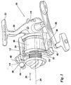
- FIG. 1 a spinning-type fishing reel, according to the present invention, is shown at 10 .
- the focus of the present invention is on the rotor 12 , and more specifically the "bail” or “bail wire” 14 , which is operable to wrap a supply of line around a spool 16 at the front of the reel 10 .
- the reel 10 described herein is only exemplary of the environment for the invention. Many variations in the configuration of the reel 10 shown are contemplated by the invention.
- the reel 10 has a main housing 18 which encases an operating mechanism (not shown).
- the housing 18 has an integrally formed stem 20 which terminates at a foot 22 which is attachable to a fishing rod (not shown) by conventional means.
- the rotor 12 is rotated about a central longitudinal axis 24 by a crank handle 26 which is interrelated to the operating mechanism. As this occurs, the rotor 12 wraps the line continuously about the spool 16 .
- the operating mechanism includes structure for oscillating the spool 16 in a fore and aft direction, as indicated by the double-headed arrow 28 , as the rotor 12 rotates, to thereby assure that the line is evenly distributed along the axial extent of the spool 16 .
- the rotor 12 has a skirt 30 , a spool shoulder 32 and diametrically, oppositely located first and second ears 34 , 36 , which cooperatively define a support for a movable bail assembly 38 .
- the bail assembly 38 has a first bail arm 40 mounted to the first bail ear 34 and a second bail arm 42 mounted to the second bail ear 36 .
- the ends of U-shaped bail wire 14 are fixedly attached, one each to the bail arms 40 , 42 , so that the bail arms 40 , 42 and bail wire 14 are movable as a unit.
- the first bail arm 40 is connected to the first bail ear 34 to be pivotable relative thereto about an axis.
- the second bail arm 42 is attached to the second bail ear 36 for pivoting movement relative thereto about a parallel axis.
- the bail assembly 38 is pivotable as a unit relative to the rotor 12 about the axes between a cast position and a retrieve position.
- an over-center bias mechanism (not shown) within at least one of the bail ears 34 , 36 , the bail arms 40 , 42 , and thus the entire bail assembly 38 , are biased into the cast and retrieve positions as the bail assembly 38 approaches each.
- Suitable structure for pivotably attaching the bail assembly 38 to the body 30 and for biasing the bail assembly 38 into the cast and retrieve positions is well known in the art.
- one suitable structure is described in detail in U.S. Patent No. 5,004,182, to Councilman, which is incorporated herein by reference.
- the line In the transition from the cast position to the retrieve position, the line is guided along an edge of the bail wire 14 and onto a line roller 44 . With the reel 10 in the retrieve position, the line extends from the spool 16 , around the cylindrical line roller 44 , and forwardly from the line roller 44 away from the reel 10 .
- crank handle 26 With the bail assembly 38 in the retrieve position causes the rotor 12 to rotate clockwise about the axis 24 as viewed from the front of the spool 16 . This brings the line against the line roller 44 and causes the line to wrap around the spool 16 as the rotor 12 rotates.
- Deflection as related to a bail wire is linearly related to the load divided by the product of the multiplicands E and I, where E is the modulus of elasticity (stiffness) of the bail wire material and I is the moment of inertia (related only to the shape of the bail wire's cross section).
- E is the modulus of elasticity (stiffness) of the bail wire material
- I is the moment of inertia (related only to the shape of the bail wire's cross section).
- Most bail designs utilize round stainless steel wire which has a moment of inertia (I) equal to 1 ⁇ 4 ⁇ r 4 .
- the diameters range from 0.08 to 0.11 in. (2-2.8 mm) resulting in a calculated moment of inertia between 0.20 ⁇ 10 -5 in. 4 and 0.72 ⁇ 10 -5 in. 4
- Elasticity of stainless steel wire ranges generally from 26 to 30 million psi.
- one bail design utilizing a plastic molded bail transitions from a rectangular shape to an elliptical shape.
- the moment of inertia for this design varies from approximately 1.4 ⁇ 10 -4 in. 4 to 1.0 ⁇ 10 -2 in. 4 in one direction and from 0.45 ⁇ 10 -2 in. 4 to 2.0 ⁇ 10 -2 in.
- the present invention employs in one aspect a bail wire preselected to possess a product of E ⁇ I at or below 45 lbs.-in. 2 and, most preferably, around 5 lbs.-in. 2
- E is approximately 8 million psi
- I is approximately 6.4 ⁇ 10 -7 in. 4
- the inventive bail wire is preselected to possess a heretofore unachievably low weight per unit length.
- the aforedescribed stainless steel bails have a weight per unit length from approximately 1.3 ⁇ 10 -3 to 2.7 ⁇ 10 -3 lbs./in.
- the known plastic bails, having a density of approximately 0.04 lbs./in. 3 and a cross section varying from 0.03 to 0.09 in. 2 possess a weight per unit of length ranging from approximately 1.2 ⁇ 10 -3 to 4.0 ⁇ 10 -3 lbs./in.
- the inventive bail provided herein has a weight per unit length equal to or less than 1.0 ⁇ 10 -3 lbs./in. and, most preferably, of about 0.7 ⁇ 10 -3 lbs./in. Utilizing such a bail wire whose weight per unit length is at or below this range is results in improved reel balance and performance.
- a nickel-titanium alloy bail wire and, most preferably, a cylindrical nickel-titanium bail wire containing 55-56 weight percent nickel and 44-45 weight percent titanium (about 50 atomic percent each).
- the inventive bail wire has an optimal diameter of about 0.06 in. and a density of about 0.25 lbs./in. 3 Its modulus of elasticity is approximately 8 million psi, and it possesses a moment of inertia of about 6.4 ⁇ 10 -7 in. 4 Consequently, in the most preferred inventive bail wire the value of E ⁇ I is 5.12 lbs.-in. 2 and its weight per unit length is 0.71 ⁇ 10 -3 lbs./in.
- Nitinol exhibits two unique properties depending upon its particular composition and the manner in which it is prepared, that is, “shape memory” and “superelasticity".
- shape memory effect describes the process of restoring the original shape of a plastically deformed sample by heating it to achieve a crystalline phase change known as “thermoelastic martensitic transformation”.
- transition (or transformation) temperature nitinol has a soft "martensitic” microstructure which is deformable. Heating the material converts it to its high strength, austenitic condition. The transformation to and from the two states can be repeated by subjecting the material to heating and cooling cycles.
- the superelasticity effect is achieved when the alloy is stress induced in a temperature range above the transition temperature. This effect is caused by the stress-induced formation of some martensite above its normal temperature. Because it has been formed above its normal temperature, the martensite reverts, i.e., springs back, immediately to undeformed austenite as soon as the stress is removed.
- the preferred nitinol bail wire is locked in its austenite form through the temperature variants it will experience during use so that it may exhibit superelasticity.
- the inventive bail wire is constructed of austenitic nitinol having the preferred composition described above, a transition temperature (i.e., an austenitic finish temperature) of -25° C ⁇ 5° C and exhibiting superelasticity in a temperature range of -25° C to 40° C.
- the shape of the inventive bail wire is set by constraining the nitinol element on a fixture of the desired shape and applying an appropriate heat treatment as is known in the art.
- FIG. 2 demonstrates the flexibility of the preferred bail wire composition as compared to stainless steel wire and titanium spring wire.
- the nickel titanium wire exhibits an elastic recovery percentage of approximately 95% as compared to 50% for stainless steel and 70% for titanium spring wire.
- This unique bail wire property may also be characterized with reference to the elastic limit of the bail wire material, meaning the degree to which it may be strained without incurring permanent deformation.
Landscapes
- Life Sciences & Earth Sciences (AREA)
- Environmental Sciences (AREA)
- Animal Husbandry (AREA)
- Biodiversity & Conservation Biology (AREA)
- Ropes Or Cables (AREA)
- Storage Of Web-Like Or Filamentary Materials (AREA)
Applications Claiming Priority (2)
| Application Number | Priority Date | Filing Date | Title |
|---|---|---|---|
| US09/311,945 US6076756A (en) | 1999-05-14 | 1999-05-14 | Superelastic, lightweight bail wire for spinning fishing reels |
| US311945 | 1999-05-14 |
Publications (1)
| Publication Number | Publication Date |
|---|---|
| EP1051905A1 true EP1051905A1 (fr) | 2000-11-15 |
Family
ID=23209175
Family Applications (1)
| Application Number | Title | Priority Date | Filing Date |
|---|---|---|---|
| EP00302068A Withdrawn EP1051905A1 (fr) | 1999-05-14 | 2000-03-14 | Arceau, superélastique et léger pour moulinet de pêche |
Country Status (6)
| Country | Link |
|---|---|
| US (2) | US6076756A (fr) |
| EP (1) | EP1051905A1 (fr) |
| JP (1) | JP2000342130A (fr) |
| KR (1) | KR100335248B1 (fr) |
| CN (1) | CN1273774A (fr) |
| NO (1) | NO20002405L (fr) |
Families Citing this family (15)
| Publication number | Priority date | Publication date | Assignee | Title |
|---|---|---|---|---|
| US6076756A (en) | 1999-05-14 | 2000-06-20 | Brunswick Corporation | Superelastic, lightweight bail wire for spinning fishing reels |
| US7976648B1 (en) | 2000-11-02 | 2011-07-12 | Abbott Cardiovascular Systems Inc. | Heat treatment for cold worked nitinol to impart a shape setting capability without eventually developing stress-induced martensite |
| US6602272B2 (en) | 2000-11-02 | 2003-08-05 | Advanced Cardiovascular Systems, Inc. | Devices configured from heat shaped, strain hardened nickel-titanium |
| US6626937B1 (en) * | 2000-11-14 | 2003-09-30 | Advanced Cardiovascular Systems, Inc. | Austenitic nitinol medical devices |
| US6855161B2 (en) | 2000-12-27 | 2005-02-15 | Advanced Cardiovascular Systems, Inc. | Radiopaque nitinol alloys for medical devices |
| US20020152668A1 (en) * | 2001-04-19 | 2002-10-24 | Lybarger Michael A. | Superelastic fishing rod |
| US7942892B2 (en) | 2003-05-01 | 2011-05-17 | Abbott Cardiovascular Systems Inc. | Radiopaque nitinol embolic protection frame |
| US7222809B1 (en) | 2005-11-14 | 2007-05-29 | W.C. Bradley/Zebco Holdings, Inc. | Bail assembly for spinning reel |
| US7681821B2 (en) * | 2008-02-13 | 2010-03-23 | W.C. Bradley/Zebco Holdings, Inc. | Demonstration mode for electronic fishing reel |
| US8096493B2 (en) * | 2008-04-08 | 2012-01-17 | Bennis Gary L | Bail release mechanism for spinning reels |
| US7896277B2 (en) * | 2008-08-04 | 2011-03-01 | William Lombardo | Fishing reel |
| US7922112B2 (en) * | 2009-04-20 | 2011-04-12 | Zeebaas, Llc | Bail for spinning reel |
| US8708268B2 (en) | 2011-10-11 | 2014-04-29 | William Joseph Lombardo | Fishing reel |
| USD861827S1 (en) | 2017-07-11 | 2019-10-01 | W.C. Bradley/Zebco Holdings, Inc. | Spinning reel |
| KR102367102B1 (ko) * | 2021-08-03 | 2022-02-23 | 장정필 | 낚시채비와 리드줄 결합방법 |
Citations (10)
| Publication number | Priority date | Publication date | Assignee | Title |
|---|---|---|---|---|
| US4426045A (en) | 1979-10-18 | 1984-01-17 | Brunswick Corporation | Bail trip mechanism for fishing reel |
| US4676450A (en) | 1984-01-06 | 1987-06-30 | Brunswick Corporation | Quick bail opening system for fishing reel |
| US4895438A (en) | 1983-12-06 | 1990-01-23 | Cvi/Beta Ventures, Inc. | Eyeglass frame including shape-memory elements |
| US5004182A (en) | 1988-06-15 | 1991-04-02 | Zebco Corporation | Convertible bail opening system |
| JPH03236732A (ja) * | 1989-12-04 | 1991-10-22 | Nippon Seisen Co Ltd | 釣り竿の穂先 |
| DE4307593C1 (de) * | 1993-03-10 | 1994-08-04 | Fraunhofer Ges Forschung | Fadenstrukturkörper |
| US5637089A (en) | 1990-12-18 | 1997-06-10 | Advanced Cardiovascular Systems, Inc. | Superelastic guiding member |
| US5713529A (en) | 1995-04-10 | 1998-02-03 | Zebco Div. Of Brunswick Corporation | Balanced rotor spinning fishing reel |
| WO1998024309A1 (fr) * | 1996-12-06 | 1998-06-11 | Outdoor Innovations, L.L.C. | Leurres de type cuillere tournante et bas de ligne en cable ou fil metallique |
| WO2000016613A1 (fr) * | 1998-09-24 | 2000-03-30 | Blanchette Paul J | Guides de cannes a peche, tetes et accroche-hameçons et procede associe |
Family Cites Families (5)
| Publication number | Priority date | Publication date | Assignee | Title |
|---|---|---|---|---|
| DE3604700A1 (de) * | 1986-02-14 | 1987-08-20 | Kuntze Angelgeraete Dam | Schnurfangbuegel |
| JPS6351773U (fr) * | 1986-09-22 | 1988-04-07 | ||
| US5547140A (en) * | 1992-05-13 | 1996-08-20 | Shimano, Inc. | Spinning reel having an anti-reverse mechanism |
| US5203103A (en) * | 1992-09-02 | 1993-04-20 | Hawley James M | Action fishing lure |
| US6076756A (en) | 1999-05-14 | 2000-06-20 | Brunswick Corporation | Superelastic, lightweight bail wire for spinning fishing reels |
-
1999
- 1999-05-14 US US09/311,945 patent/US6076756A/en not_active Expired - Lifetime
-
2000
- 2000-03-14 EP EP00302068A patent/EP1051905A1/fr not_active Withdrawn
- 2000-03-17 US US09/527,756 patent/US6257513B1/en not_active Expired - Lifetime
- 2000-04-04 KR KR1020000017528A patent/KR100335248B1/ko not_active Expired - Fee Related
- 2000-04-27 JP JP2000127395A patent/JP2000342130A/ja active Pending
- 2000-05-09 NO NO20002405A patent/NO20002405L/no unknown
- 2000-05-12 CN CN00108536A patent/CN1273774A/zh active Pending
Patent Citations (11)
| Publication number | Priority date | Publication date | Assignee | Title |
|---|---|---|---|---|
| US4426045A (en) | 1979-10-18 | 1984-01-17 | Brunswick Corporation | Bail trip mechanism for fishing reel |
| US4895438A (en) | 1983-12-06 | 1990-01-23 | Cvi/Beta Ventures, Inc. | Eyeglass frame including shape-memory elements |
| US4676450A (en) | 1984-01-06 | 1987-06-30 | Brunswick Corporation | Quick bail opening system for fishing reel |
| US4676450B1 (en) | 1984-01-06 | 1991-06-25 | Quick bail opening system for fishing reel | |
| US5004182A (en) | 1988-06-15 | 1991-04-02 | Zebco Corporation | Convertible bail opening system |
| JPH03236732A (ja) * | 1989-12-04 | 1991-10-22 | Nippon Seisen Co Ltd | 釣り竿の穂先 |
| US5637089A (en) | 1990-12-18 | 1997-06-10 | Advanced Cardiovascular Systems, Inc. | Superelastic guiding member |
| DE4307593C1 (de) * | 1993-03-10 | 1994-08-04 | Fraunhofer Ges Forschung | Fadenstrukturkörper |
| US5713529A (en) | 1995-04-10 | 1998-02-03 | Zebco Div. Of Brunswick Corporation | Balanced rotor spinning fishing reel |
| WO1998024309A1 (fr) * | 1996-12-06 | 1998-06-11 | Outdoor Innovations, L.L.C. | Leurres de type cuillere tournante et bas de ligne en cable ou fil metallique |
| WO2000016613A1 (fr) * | 1998-09-24 | 2000-03-30 | Blanchette Paul J | Guides de cannes a peche, tetes et accroche-hameçons et procede associe |
Non-Patent Citations (2)
| Title |
|---|
| PATENT ABSTRACTS OF JAPAN vol. 016, no. 020 (C - 0902) 20 January 1992 (1992-01-20) * |
| STOECKEL D ET AL: "SUPERELASTIC NI-TI WIRE", WIRE JOURNAL INTERNATIONAL,US,GUILFORD, CT, vol. 24, no. 1, 1991, pages 45 - 50, XP002063124, ISSN: 0277-4275 * |
Also Published As
| Publication number | Publication date |
|---|---|
| KR20010014685A (ko) | 2001-02-26 |
| US6076756A (en) | 2000-06-20 |
| JP2000342130A (ja) | 2000-12-12 |
| KR100335248B1 (ko) | 2002-05-06 |
| CN1273774A (zh) | 2000-11-22 |
| NO20002405D0 (no) | 2000-05-09 |
| NO20002405L (no) | 2000-11-15 |
| US6257513B1 (en) | 2001-07-10 |
Similar Documents
| Publication | Publication Date | Title |
|---|---|---|
| US6257513B1 (en) | Spinning reel with improved bail | |
| KR100695899B1 (ko) | 스피닝릴의 베일 반전장치 | |
| JPH10276629A (ja) | スピニングリールのベールアーム | |
| JP2007006710A (ja) | 両軸受リール | |
| US20070267108A1 (en) | Movable mechanism | |
| KR20030055176A (ko) | 스피닝 릴의 베일 반전 장치 | |
| HK1034877A (en) | Superelastick, lightweight bail wire for spinning type fishing reels | |
| US6971599B2 (en) | Spinning reel rotor braking device | |
| US20020152668A1 (en) | Superelastic fishing rod | |
| JP3470855B2 (ja) | スピニングリールのベールアーム | |
| JP7830170B2 (ja) | 釣竿用錘及び釣竿 | |
| JP4324461B2 (ja) | スピニングリールのロータ制動装置 | |
| US20070033855A1 (en) | Flexible segment fishing pole | |
| AU2020225376B2 (en) | Fishing rod | |
| KR100745314B1 (ko) | 스피닝릴 | |
| JP2005176779A5 (fr) | ||
| JP2895897B2 (ja) | スピニングリール | |
| JP4711968B2 (ja) | 可動機構 | |
| JP3555984B2 (ja) | 釣り竿 | |
| JP2573322Y2 (ja) | スピニングリール | |
| JP3753414B2 (ja) | スピニングリールのロータ制動装置 | |
| JP4307043B2 (ja) | 超弾性動力装置および動力蓄積ユニット | |
| JPH02205648A (ja) | バネ材 | |
| JP2003310113A (ja) | スピニングリールのロータ制動装置 | |
| GB2280152A (en) | Variable length fishing reel crank arm |
Legal Events
| Date | Code | Title | Description |
|---|---|---|---|
| PUAI | Public reference made under article 153(3) epc to a published international application that has entered the european phase |
Free format text: ORIGINAL CODE: 0009012 |
|
| AK | Designated contracting states |
Kind code of ref document: A1 Designated state(s): DE ES FR GB IT |
|
| AX | Request for extension of the european patent |
Free format text: AL;LT;LV;MK;RO;SI |
|
| 17P | Request for examination filed |
Effective date: 20010504 |
|
| AKX | Designation fees paid |
Free format text: DE ES FR GB IT |
|
| RAP1 | Party data changed (applicant data changed or rights of an application transferred) |
Owner name: ZEBCO SPORTS EUROPE (HOLDINGS) LIMITED |
|
| 17Q | First examination report despatched |
Effective date: 20050623 |
|
| STAA | Information on the status of an ep patent application or granted ep patent |
Free format text: STATUS: THE APPLICATION IS DEEMED TO BE WITHDRAWN |
|
| 18D | Application deemed to be withdrawn |
Effective date: 20051001 |