EP1052356B1 - Vorrichtung zum Verschliessen einer Fahrzeugtür - Google Patents
Vorrichtung zum Verschliessen einer Fahrzeugtür Download PDFInfo
- Publication number
- EP1052356B1 EP1052356B1 EP00109711A EP00109711A EP1052356B1 EP 1052356 B1 EP1052356 B1 EP 1052356B1 EP 00109711 A EP00109711 A EP 00109711A EP 00109711 A EP00109711 A EP 00109711A EP 1052356 B1 EP1052356 B1 EP 1052356B1
- Authority
- EP
- European Patent Office
- Prior art keywords
- closure element
- lever
- carrier part
- coupling element
- locked position
- Prior art date
- Legal status (The legal status is an assumption and is not a legal conclusion. Google has not performed a legal analysis and makes no representation as to the accuracy of the status listed.)
- Expired - Lifetime
Links
- 230000008878 coupling Effects 0.000 claims description 23
- 238000010168 coupling process Methods 0.000 claims description 23
- 238000005859 coupling reaction Methods 0.000 claims description 23
- 238000006073 displacement reaction Methods 0.000 claims description 5
- 230000000284 resting effect Effects 0.000 claims 1
- 230000006835 compression Effects 0.000 description 2
- 238000007906 compression Methods 0.000 description 2
- 230000006978 adaptation Effects 0.000 description 1
- 230000005540 biological transmission Effects 0.000 description 1
- 230000007257 malfunction Effects 0.000 description 1
- 238000004519 manufacturing process Methods 0.000 description 1
Images


Classifications
-
- E—FIXED CONSTRUCTIONS
- E05—LOCKS; KEYS; WINDOW OR DOOR FITTINGS; SAFES
- E05B—LOCKS; ACCESSORIES THEREFOR; HANDCUFFS
- E05B81/00—Power-actuated vehicle locks
- E05B81/12—Power-actuated vehicle locks characterised by the function or purpose of the powered actuators
- E05B81/20—Power-actuated vehicle locks characterised by the function or purpose of the powered actuators for assisting final closing or for initiating opening
- E05B81/22—Power-actuated vehicle locks characterised by the function or purpose of the powered actuators for assisting final closing or for initiating opening by movement of the striker
-
- E—FIXED CONSTRUCTIONS
- E05—LOCKS; KEYS; WINDOW OR DOOR FITTINGS; SAFES
- E05B—LOCKS; ACCESSORIES THEREFOR; HANDCUFFS
- E05B81/00—Power-actuated vehicle locks
- E05B81/54—Electrical circuits
- E05B81/90—Manual override in case of power failure
Definitions
- the invention relates to a device for closing a vehicle door, hood provided with a door lock, Luggage compartment lid, tailgate or the like, the device a bolt or bow-shaped arranged on a carrier part Closing element comprises, and wherein the closing element on the one hand with the help of a drive motor with a downstream Gearbox containing drive device against the pressure of at least one spring from one to the other Locking position is movable and on the other hand in the Unlocked position by one assigned to the door lock pivotable fork latch can be gripped so that the closing element when moving into the locked position the fork latch the vehicle door etc. in its closed Position.
- Such a closing or closing aid for vehicle doors etc. is known for example from DE 197 37 996 A1.
- the carrier part of the closing element shifted by means of a drive device which drives an eccentric with a control cam, which directly on the edge areas of a recess of the carrier part acts.
- the recess points in the direction of movement Carrier part on a clear measure that the outer diameter corresponds to the movement path of the eccentric.
- a disadvantage of this known device is, among other things, that the carrier part of the closing element is relatively complex is built up because it is one of the trajectory of the eccentric has a correspondingly wide recess and on the other hand must have sufficient stability.
- Another disadvantage is that to close the vehicle door if the drive device fails, a separate manual setting device is provided, by means of which the carrier part the locking element manually in the locking position moved and then in this position must be fixed.
- From DE 196 16 655 A1 is also a locking aid generic device known for vehicle doors, in which the displacement of the closing element receiving carrier part by a directly on the carrier part acting drive device takes place. It presses in against the cam rotated by the drive device a driver arranged on the carrier part until the carrier part by a swiveling spring-loaded catch lever in its locking position is fixed. Then will the cam then continued to rotate until it did not is more engaged with the driver.
- the catch lever is either by means of of a separate drive or via one with the drive device connected gear swiveled out of the fixing position.
- This known device has compared to DE 197 37 996 A1, inter alia, the advantages that a recess in not the carrier part of the closing element for an eccentric is required and that to close the vehicle door Failure of the drive means a manual shift of the Carrier part can be omitted in the locking position, because the catch lever also takes on this function, but is at the known device a relatively space-consuming drive device required.
- 199 10 031.4 is a generic device known in the between that of the drive device actuated control cam and the support part of the closing element a tab-shaped coupling element is provided, which contains a first recess into which the control cam has a positive fit engages and which one designed as an elongated hole contains second recess, in one with the carrier part of the closing element connected pin-shaped extension intervenes.
- the length of the elongated hole is chosen such that that the locking element is in the unlocked position manually without hindrance by the control cam in its Locking position is displaceable.
- This device is also relatively space-consuming since the entire Carrier part of the closing element slidably mounted have to be.
- the present invention is based on the 199 10 031.4 the task of a device of the type mentioned Specify type that is simple and space-saving is.
- the invention is essentially based on the thought rather than a slidable carrier part a pivotable Carrier part to use.
- a carrier part a e.g. two-armed bell crank proven first lever arm over the pin-shaped extension the coupling element and on its second lever arm the closing element is arranged.
- a pivotable support part is simple to manufacture and to save space on the vehicle it has the advantage that by appropriate assignment coupling and closing element in a simple way an adaptation of the device according to the invention to the given space conditions can be made.
- the coupling element has proven to be advantageous and the closing element in this way on the carrier part to arrange that with an axial displacement of the Coupling element, the closing element in a direction of movement of the coupling element moves approximately in the vertical direction.
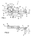
- FIG. 1 shows a device according to the invention, e.g. as a closing aid for closing the tailgate used a motor vehicle, not shown becomes.
- the device 1 is on the rear body attached to the vehicle in the area of the tailgate opening, opposite the tailgate door lock.
- the device 1 comprises a drive device 2 with a Drive motor 3 (Fig.2) and a downstream of the motor Gear 4.
- the gear 4 has a cam wheel 5 with eccentric to the central axis 6 arranged control cam 7, which in a first recess 8 displaceable in the axial direction rod-shaped coupling element 9 engages positively.
- the coupling element 9 also has an axially extending slot 10, in which one with the first Lever arm 11 of a bell crank 12 engages connected pin 13.
- a locking bolt 15 attached, which is dashed by a shown, the fork lock 16 associated with the door lock is.
- the bell crank 12 is by a torsion spring 17th in its initial position shown in FIGS. 1 and 2 (unlocked position) held, the first lever arm 11 on abuts a stop designated 18 and the pin 13 is supported on one end 19 of the elongated hole 10.
- the device 1 further comprises a pivotally arranged Catch lever 20 by a compression spring 21 against the first Lever arm 11 of the bell crank 12 is pressed.
- a control lever 22 is pivotably arranged on the coupling element 9, its function is described in more detail below becomes.
- FIG. 1 and 2 show the locking bolt 15 in the unlocked position.
- the tailgate of the not shown Vehicle leaned against the rear body and the door lock may be in its pre-locked position, in which the fork latch 16 includes the locking bolt 15 and is secured by a pawl, not shown.
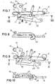
- Simultaneously with the securing of the fork latch 16 by the Pawl is e.g. located in the door lock Microswitch of the drive motor 3 (Fig.2) of the invention Device 1 activated and the cam wheel 5 rotates from the position shown in Figure 1 counterclockwise (Fig.3-8).
- the control cam 7 presses against the rod-shaped coupling element 9 and moves it in the direction of its longitudinal axis 23.
- the end 19 of the elongated hole 10 acting as a stop presses against the pin 13 and thereby pivots the bell crank 12 against the pressure of the torsion spring 17 in the direction of with 24 designated arrow (Fig.1).
- the Lock bolt 15 with the fork latch 16 of the door lock so that defines the tailgate of the corresponding vehicle against the one between the tailgate and the body Rubber seal (not shown) is pulled.
- the tailgate of the corresponding vehicle can also be operated manually be closed so that the locking bolt 15 manually is pressed from the unlocked to the locked position.
- the drive motor 3 then turns the cam wheel 5 until the Control cam 7 via the intermediate positions shown in Figs. 3-6 moved to the position shown in Figure 7 becomes.
- the invention is of course not based on the above described embodiment limited.
- the pivoting support part also moving cause a striker.
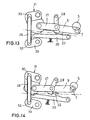
- a corresponding embodiment give the Fig.13 and 14 again, Fig.13 with the 29 designated striker in its unlocked position and Fig. 14 the striker in its locked position shows.
Landscapes
- Lock And Its Accessories (AREA)
Description
- Fig.1
- die Seitenansicht einer erfindungsgemäßen Vorrichtung mit Nockenrad und einem bolzenförmigen Schließelement, wobei sich das Schließelement in seiner Entriegelungsstellung befindet;
- Fig.2
- den Längsschnitt der in Fig.1 dargestellten erfindungsgemäßen Vorrichtung entlang der dort mit II-II bezeichneten Schnittlinie;
- Fig.3-12
- den Fig.1 und 2 entsprechende Ansichten der erfindungsgemäßen Vorrichtung bei unterschiedlichen Stellungen des Nockenrades;
- Fig.13 und 14
- zwei Seitenansichten einer weiteren erfindungsgemäßen Vorrichtung mit einem bügelförmigen Schließelement, wobei sich das Schließelement zum einen in seiner Entriegelungsstellung (Fig.13) und zum anderen in seiner Verriegelungsstellung (Fig.14) befindet.
- 1
- Vorrichtung
- 2
- Antriebseinrichtung
- 3
- Antriebsmotor
- 4
- Getriebe
- 5
- Nockenrad
- 6
- Mittelachse (Nockenrad)
- 7
- Steuernocken
- 8
- erste Ausnehmung
- 9
- Koppelelement
- 10
- Langloch, Ausnehmung
- 11
- erster Hebelarm
- 12
- Umlenkhebel, Trägerteil
- 13
- Zapfen
- 14
- zweiter Hebelarm
- 15
- Schließbolzen, Schließelement
- 16
- Gabelfalle
- 17
- Drehfeder, Feder
- 18
- Anschlag
- 19
- Ende (Langloch)
- 20
- Fanghebel
- 21
- Druckfeder
- 22
- Steuerhebel
- 23
- Längsachse
- 24
- Pfeil
- 25
- Sperrnase
- 26
- Rastnut
- 27
- Verbindungshebel
- 28
- Betätigungshebel
- 29
- Schließbügel, Schließelement
- 30
- erste Schenkel
- 31
- Trägerteil
- 32
- zweite Schenkel
- 33
- Flanschplatte
Claims (7)
- Vorrichtung zum Verschließen einer mit einem Türschloß versehenen Fahrzeugtür, Motorhaube, Kofferraumdeckel, Heckklappe o.dgl., wobei die Vorrichtung (1) ein auf einem Trägerteil (12;31) angeordnetes bolzen- oder bügelförmiges Schließelement (15;29) umfaßt, und wobei das Schließelement (15;29) einerseits mit Hilfe einer einen Antriebsmotor (3) mit nachgeschaltetem Getriebe (4) enthaltenden Antriebseinrichtung (2) gegen den Druck mindestens einer Feder (17) von einer Ent- in eine verriegelungsstellung bewegbar ist und andererseits in der Entriegelungsstellung durch eine dem Türschloß zugeordnete schwenkbare Gabelfalle (16) umgreifbar ist, so daß das Schließelement (15;29) bei seiner Bewegung in die Verriegelungsstellung über die Gabelfalle (16) die Fahrzeugtür in deren geschlossene Stellung zieht, mit den Merkmalen:a) das Getriebe (4) der Antriebseinrichtung (2) umfaßt ein Nockenrad (5) mit einem exzentrisch zur Mittelachse (6) angeordneten Steuernocken (7);b) das Trägerteil (12;31) des Schließelementes (15;29) ist mit einem stangenförmig ausgebildeten Koppelelement (9) verbunden, welches durch den Steuernokken (7) in axialer Richtung verschiebbar ist und welches eine als Langloch ausgebildete Ausnehmung (10) enthält, in die ein mit dem Trägerteil (12;31) verbundener Zapfen (13) eingreift, der sich an dem einen Ende (19) des Langloches (10) abstützt, derart, daß bei Drehung des Nockenrades (5) über eine entsprechende Verschiebung des Koppelelementes (9) das Schließelement (15;29) von der Ent- in die Verriegelungsstellung und umgekehrt bewegbar ist;c) das Trägerteil (12;31) des Schließelementes (15;29) ist schwenkbar ausgebildet, so daß eine Verschiebung des Koppelelementes (9) ein entsprechendes Verschwenken des Schließelementes (15;29) bewirkt undd) die Länge des Langloches (10) des Koppelelementes (9) ist derart gewählt, daß das in der Entriegelungsstellung befindliche Schließelement (15;29) manuell ohne Behinderungen durch den Steuernocken (7) in seine Verriegelungsstellung verschiebbar ist.
- Vorrichtung nach Anspruch 1, dadurch gekennzeichnet, daß das Trägerteil (12) als zweiarmiger Umlenkhebel ausgebildet ist, wobei an dem ersten Hebelarm (11) über den Zapfen (13) das Koppelelement (9) und an dem zweiten Hebelarm (14) das Schließelement (15;29) angeordnet ist.
- Vorrichtung nach Anspruch 1 oder 2, dadurch gekennzeichnet, daß die Vorrichtung (1) einen schwenkbar angeordneten federbeaufschlagten Fanghebel (20) umfaßt, der das Trägerteil (12;31) des Schließelementes (15;29) nach Erreichen der Verriegelungsstellung des Schließelementes (15;29) in dieser Stellung fixiert.
- Vorrichtung nach Anspruch 3, dadurch gekennzeichnet, daß ein an dem Koppelelement (9) angeordneter Steuerhebel (22) vorgesehen ist, derart, daß nach Erreichen der Verriegelungsstellung des Schließelementes (15;29) der Steuerhebel (22) bei Weiterdrehung des Nockenrades (5) den Fanghebel (20) aus seiner Fixierstellung drückt, so daß das Schließelement (15;29) wieder in seine Entriegelungsstellung verschiebbar ist.
- Vorrichtung nach einem der Ansprüche 1 bis 4, dadurch gekennzeichnet, daß das Koppelelement (9) und das Schließelement (15;29) derart an dem Trägerteil (12;31) angeordnet sind, daß sich bei einer axialen Verschiebung des Koppelelementes (9) das Schließelement (15;29) in einer zur Bewegungsrichtung des Koppelelementes (9) etwa senkrechten Richtung bewegt.
- Vorrichtung nach einem der Ansprüche 1 bis 5, dadurch gekennzeichnet, daß es sich bei dem Schließelement (29) um einen Schließbügel handelt, dessen erster Schenkel (30) an dem schwenkbar angeordneten Trägerteil (31) und dessen zweiter Schenkel (32) an einer schwenkbar angeordneten Flanschplatte (33) befestigt ist.
- Vorrichtung nach einem der Ansprüche 4 bis 6, dadurch gekennzeichnet, daß der Umlenkhebel (12) über einen Verbindungshebel (27) mit einem Betätigungshebel (28) verbunden ist, welcher ein Verschwenken des Steuerhebels (22) unmittelbar nach Freigabe des Umlenkhebels (12) bewirkt, so daß bei einem direkt nach dem Umschwenken des Steuerhebels (22) auftretenden Stromausfall das Schließelement (15;29) manuell wieder in die Position "geschlossen" gebracht werden kann.
Applications Claiming Priority (2)
| Application Number | Priority Date | Filing Date | Title |
|---|---|---|---|
| DE19921517A DE19921517C2 (de) | 1999-05-10 | 1999-05-10 | Vorrichtung zum Verschließen einer Fahrzeugtür |
| DE19921517 | 1999-05-10 |
Publications (2)
| Publication Number | Publication Date |
|---|---|
| EP1052356A1 EP1052356A1 (de) | 2000-11-15 |
| EP1052356B1 true EP1052356B1 (de) | 2004-05-06 |
Family
ID=7907594
Family Applications (1)
| Application Number | Title | Priority Date | Filing Date |
|---|---|---|---|
| EP00109711A Expired - Lifetime EP1052356B1 (de) | 1999-05-10 | 2000-05-08 | Vorrichtung zum Verschliessen einer Fahrzeugtür |
Country Status (3)
| Country | Link |
|---|---|
| EP (1) | EP1052356B1 (de) |
| DE (1) | DE19921517C2 (de) |
| ES (1) | ES2220289T3 (de) |
Cited By (1)
| Publication number | Priority date | Publication date | Assignee | Title |
|---|---|---|---|---|
| DE202010014396U1 (de) | 2010-10-16 | 2012-01-17 | Kiekert Ag | Antriebseinheit für eine Kraftfahrzeugtür-Schließeinrichtung |
Families Citing this family (18)
| Publication number | Priority date | Publication date | Assignee | Title |
|---|---|---|---|---|
| US6193288B1 (en) * | 1998-07-23 | 2001-02-27 | Ohi Seisakusho Co., Ltd. | Electric lid closure |
| DE10048051A1 (de) * | 2000-09-28 | 2002-04-11 | Kiekert Ag | Verschließeinrichtung für insbesondere Kraftfahrzeug-Türen, -Heckklappen oder dergleichen |
| DE10123187B4 (de) * | 2001-05-12 | 2014-02-20 | Bayerische Motoren Werke Aktiengesellschaft | Schloss mit motorischer Schließeinrichtung |
| DE10128608A1 (de) * | 2001-06-13 | 2003-07-03 | Valeo Sicherheitssysteme Gmbh | Schließhilfe zum Verschließen einer Fahrzeugtür |
| DE10140385B4 (de) * | 2001-08-23 | 2012-06-21 | Kiekert Ag | Servo-Schlosshalter für einen Türverschluss, insbesondere Kraftfahrzeugtürverschluss |
| DE10157173A1 (de) * | 2001-11-22 | 2003-06-05 | Bosch Gmbh Robert | Schließkeil-Antriebsbaugruppe |
| DE10251375A1 (de) * | 2002-11-05 | 2004-05-13 | Valeo Sicherheitssysteme Gmbh | Schließhilfe zum Verschließen einer Fahrzeugtür |
| DE10251354B4 (de) * | 2002-11-05 | 2012-04-19 | Valeo Sicherheitssysteme Gmbh | Schließhilfe zum Verschließen einer Fahrzeugtür |
| DE10301998B4 (de) * | 2003-01-21 | 2012-03-22 | Valeo Sicherheitssysteme Gmbh | Schließhilfe zum Verschließen einer mit einem Türschloß versehenen Fahrzeugtür |
| DE10316764A1 (de) * | 2003-04-10 | 2004-10-28 | Siemens Ag | Schließbügelantrieb |
| DE10321275B4 (de) * | 2003-05-13 | 2017-07-27 | Bayerische Motoren Werke Aktiengesellschaft | Schlossanordnung für ein Fahrzeug |
| DE102004010647A1 (de) * | 2004-03-01 | 2005-09-22 | Volkswagen Ag | Bedienungshilfseinrichtung insbesondere für eine Kraftfahrzeugklappe mit Auswerfer- und Zuziehhilfseinrichtung |
| FR2871831B1 (fr) * | 2004-06-18 | 2006-09-08 | Arvinmeritor Light Vehicle Sys | Serrure a ouverture electrique |
| DE102004036655A1 (de) * | 2004-07-28 | 2006-02-16 | BÖCO Böddecker & Co. GmbH & Co. KG | Vorrichtung zum automatischen Schließen einer Fahrzeugtür |
| DE102005053649B4 (de) * | 2005-11-10 | 2007-10-25 | Audi Ag | Schließvorrichtung und Verfahren zum Betätigen eines Klappenelements eines Fahrzeugs |
| DE102005062998B4 (de) * | 2005-12-30 | 2019-04-25 | Kiekert Ag | Kraftfahrzeugtürverschluss |
| DE102008020021B4 (de) * | 2008-04-22 | 2017-10-12 | Audi Ag | Zuziehhilfsvorrichtung für einen Kofferraumverschluss |
| DE102009018188B4 (de) | 2009-04-22 | 2017-09-07 | BÖCO Böddecker & Co. GmbH & Co. KG | Vorrichtung zum automatischen Schließen einer Fahrzeugtür |
Family Cites Families (6)
| Publication number | Priority date | Publication date | Assignee | Title |
|---|---|---|---|---|
| FR2480342A1 (fr) * | 1980-04-14 | 1981-10-16 | Renault | Mecanisme de serrure electrique pour la portee de coffre d'un vehicule automobile |
| DE3721963C1 (en) * | 1987-07-03 | 1988-10-13 | Kiekert Gmbh Co Kg | Motor-vehicle door fastening |
| DE3725075C1 (de) * | 1987-07-29 | 1988-08-18 | Kiekert Gmbh Co Kg | Kraftfahrzeugtuerverschluss |
| WO1997022771A1 (en) * | 1995-12-20 | 1997-06-26 | Itt Automotive Electrical Systems, Inc. | Power striker with inertially activated impact cycle |
| DE19616655B4 (de) * | 1996-04-26 | 2005-03-10 | Valeo Sicherheitssysteme Gmbh | Vorrichtung zum Öffnen und Schließen einer Tür oder Klappe |
| DE19737996C2 (de) * | 1996-10-08 | 2002-12-19 | Bosch Gmbh Robert | Schließkeil-Antriebsbaugruppe für ein Kraftfahrzeug-Türschloß o. dgl. |
-
1999
- 1999-05-10 DE DE19921517A patent/DE19921517C2/de not_active Expired - Fee Related
-
2000
- 2000-05-08 EP EP00109711A patent/EP1052356B1/de not_active Expired - Lifetime
- 2000-05-08 ES ES00109711T patent/ES2220289T3/es not_active Expired - Lifetime
Cited By (1)
| Publication number | Priority date | Publication date | Assignee | Title |
|---|---|---|---|---|
| DE202010014396U1 (de) | 2010-10-16 | 2012-01-17 | Kiekert Ag | Antriebseinheit für eine Kraftfahrzeugtür-Schließeinrichtung |
Also Published As
| Publication number | Publication date |
|---|---|
| EP1052356A1 (de) | 2000-11-15 |
| DE19921517A1 (de) | 2000-11-30 |
| ES2220289T3 (es) | 2004-12-16 |
| DE19921517C2 (de) | 2001-03-15 |
Similar Documents
| Publication | Publication Date | Title |
|---|---|---|
| EP1052356B1 (de) | Vorrichtung zum Verschliessen einer Fahrzeugtür | |
| EP2089599B1 (de) | Schlosseinheit mit mehrteiliger sperrklinke | |
| DE19619958C2 (de) | Schloß für eine Kraftfahrzeugtür | |
| DE102008048773A1 (de) | Kraftfahrzeugtürverschluss | |
| DE19910031C2 (de) | Vorrichtung zum Verschließen einer Fahrzeugtür | |
| EP3784855B1 (de) | Kraftfahrzeugschloss | |
| EP2010739A2 (de) | Kraftfahrzeugtürverschluss | |
| DE102021118277A1 (de) | Kraftfahrzeugschloss | |
| EP2072725A2 (de) | Treibstangenverschluss | |
| EP1408186A1 (de) | Vorrichtung zur Betätigung eines Verschlusses von Türen, Klappen od. dgl., insbesondere an Fahrzeugen | |
| EP1243725B1 (de) | Schliesseinrichtung mit Zuziehhilfe | |
| DE10301998B4 (de) | Schließhilfe zum Verschließen einer mit einem Türschloß versehenen Fahrzeugtür | |
| EP1954902A1 (de) | Verschluss für klappen oder türen von fahrzeugen | |
| DE19828289A1 (de) | Verschluss, insbesondere für Fahrzeuge | |
| EP1267023B1 (de) | Schliesshilfe zum Verschliessen einer Fahrzeugtür | |
| EP1956168B1 (de) | Kraftfahrzeugtürverschluss | |
| DE102005043227B3 (de) | Kraftfahrzeugtürverschluss | |
| DE202008018160U1 (de) | Türschloß | |
| EP1418298B1 (de) | Schliesshilfe zum Verschliessen einer Fahrzeugtür | |
| DE19853160B4 (de) | Betätigungsvorrichtung für einen Kraftfahrzeug-Türverschluß | |
| EP2060714A2 (de) | Treibstangenschloss | |
| EP1567736B1 (de) | Schliesshilfe zum verschliessen einer farzeugtür | |
| DE102024131493A1 (de) | Kraftfahrzeugschloss | |
| DE102024128990A1 (de) | Kraftfahrzeugschloss | |
| WO2024240366A1 (de) | Kraftfahrzeug-griffanordnung |
Legal Events
| Date | Code | Title | Description |
|---|---|---|---|
| PUAI | Public reference made under article 153(3) epc to a published international application that has entered the european phase |
Free format text: ORIGINAL CODE: 0009012 |
|
| AK | Designated contracting states |
Kind code of ref document: A1 Designated state(s): ES FR GB IT |
|
| AX | Request for extension of the european patent |
Free format text: AL;LT;LV;MK;RO;SI |
|
| 17P | Request for examination filed |
Effective date: 20010515 |
|
| AKX | Designation fees paid |
Free format text: ES FR GB IT |
|
| REG | Reference to a national code |
Ref country code: DE Ref legal event code: 8566 |
|
| GRAP | Despatch of communication of intention to grant a patent |
Free format text: ORIGINAL CODE: EPIDOSNIGR1 |
|
| RAP1 | Party data changed (applicant data changed or rights of an application transferred) |
Owner name: VALEO GMBH & CO. SCHLIESSSYSTEME KG |
|
| GRAS | Grant fee paid |
Free format text: ORIGINAL CODE: EPIDOSNIGR3 |
|
| RAP1 | Party data changed (applicant data changed or rights of an application transferred) |
Owner name: VALEO SICHERHEITSSYSTEME GMBH |
|
| GRAA | (expected) grant |
Free format text: ORIGINAL CODE: 0009210 |
|
| AK | Designated contracting states |
Kind code of ref document: B1 Designated state(s): ES FR GB IT |
|
| REG | Reference to a national code |
Ref country code: GB Ref legal event code: FG4D Free format text: NOT ENGLISH |
|
| GBT | Gb: translation of ep patent filed (gb section 77(6)(a)/1977) |
Effective date: 20040506 |
|
| ET | Fr: translation filed | ||
| REG | Reference to a national code |
Ref country code: ES Ref legal event code: FG2A Ref document number: 2220289 Country of ref document: ES Kind code of ref document: T3 |
|
| PLBE | No opposition filed within time limit |
Free format text: ORIGINAL CODE: 0009261 |
|
| STAA | Information on the status of an ep patent application or granted ep patent |
Free format text: STATUS: NO OPPOSITION FILED WITHIN TIME LIMIT |
|
| PGFP | Annual fee paid to national office [announced via postgrant information from national office to epo] |
Ref country code: GB Payment date: 20050426 Year of fee payment: 6 |
|
| 26N | No opposition filed |
Effective date: 20050208 |
|
| PGFP | Annual fee paid to national office [announced via postgrant information from national office to epo] |
Ref country code: ES Payment date: 20050512 Year of fee payment: 6 |
|
| PG25 | Lapsed in a contracting state [announced via postgrant information from national office to epo] |
Ref country code: GB Free format text: LAPSE BECAUSE OF NON-PAYMENT OF DUE FEES Effective date: 20060508 |
|
| PG25 | Lapsed in a contracting state [announced via postgrant information from national office to epo] |
Ref country code: ES Free format text: LAPSE BECAUSE OF NON-PAYMENT OF DUE FEES Effective date: 20060509 |
|
| PGFP | Annual fee paid to national office [announced via postgrant information from national office to epo] |
Ref country code: IT Payment date: 20060531 Year of fee payment: 7 |
|
| GBPC | Gb: european patent ceased through non-payment of renewal fee |
Effective date: 20060508 |
|
| REG | Reference to a national code |
Ref country code: ES Ref legal event code: FD2A Effective date: 20060509 |
|
| PG25 | Lapsed in a contracting state [announced via postgrant information from national office to epo] |
Ref country code: IT Free format text: LAPSE BECAUSE OF NON-PAYMENT OF DUE FEES Effective date: 20070508 |
|
| PGFP | Annual fee paid to national office [announced via postgrant information from national office to epo] |
Ref country code: FR Payment date: 20100622 Year of fee payment: 11 |
|
| REG | Reference to a national code |
Ref country code: FR Ref legal event code: ST Effective date: 20120131 |
|
| PG25 | Lapsed in a contracting state [announced via postgrant information from national office to epo] |
Ref country code: FR Free format text: LAPSE BECAUSE OF NON-PAYMENT OF DUE FEES Effective date: 20110531 |