EP1052390A2 - Vorrichtung und Verfahren für das Verbessern von Übergängen zwischen Motorbetriebsarten - Google Patents
Vorrichtung und Verfahren für das Verbessern von Übergängen zwischen Motorbetriebsarten Download PDFInfo
- Publication number
- EP1052390A2 EP1052390A2 EP00303144A EP00303144A EP1052390A2 EP 1052390 A2 EP1052390 A2 EP 1052390A2 EP 00303144 A EP00303144 A EP 00303144A EP 00303144 A EP00303144 A EP 00303144A EP 1052390 A2 EP1052390 A2 EP 1052390A2
- Authority
- EP
- European Patent Office
- Prior art keywords
- controller
- correction value
- mode
- control
- air flow
- Prior art date
- Legal status (The legal status is an assumption and is not a legal conclusion. Google has not performed a legal analysis and makes no representation as to the accuracy of the status listed.)
- Withdrawn
Links
Images


Classifications
-
- F—MECHANICAL ENGINEERING; LIGHTING; HEATING; WEAPONS; BLASTING
- F02—COMBUSTION ENGINES; HOT-GAS OR COMBUSTION-PRODUCT ENGINE PLANTS
- F02D—CONTROLLING COMBUSTION ENGINES
- F02D31/00—Use of speed-sensing governors to control combustion engines, not otherwise provided for
- F02D31/001—Electric control of rotation speed
- F02D31/002—Electric control of rotation speed controlling air supply
- F02D31/003—Electric control of rotation speed controlling air supply for idle speed control
-
- F—MECHANICAL ENGINEERING; LIGHTING; HEATING; WEAPONS; BLASTING
- F02—COMBUSTION ENGINES; HOT-GAS OR COMBUSTION-PRODUCT ENGINE PLANTS
- F02D—CONTROLLING COMBUSTION ENGINES
- F02D11/00—Arrangements for, or adaptations to, non-automatic engine control initiation means, e.g. operator initiated
- F02D11/06—Arrangements for, or adaptations to, non-automatic engine control initiation means, e.g. operator initiated characterised by non-mechanical control linkages, e.g. fluid control linkages or by control linkages with power drive or assistance
- F02D11/10—Arrangements for, or adaptations to, non-automatic engine control initiation means, e.g. operator initiated characterised by non-mechanical control linkages, e.g. fluid control linkages or by control linkages with power drive or assistance of the electric type
- F02D11/105—Arrangements for, or adaptations to, non-automatic engine control initiation means, e.g. operator initiated characterised by non-mechanical control linkages, e.g. fluid control linkages or by control linkages with power drive or assistance of the electric type characterised by the function converting demand to actuation, e.g. a map indicating relations between an accelerator pedal position and throttle valve opening or target engine torque
-
- F—MECHANICAL ENGINEERING; LIGHTING; HEATING; WEAPONS; BLASTING
- F02—COMBUSTION ENGINES; HOT-GAS OR COMBUSTION-PRODUCT ENGINE PLANTS
- F02D—CONTROLLING COMBUSTION ENGINES
- F02D41/00—Electrical control of supply of combustible mixture or its constituents
- F02D41/02—Circuit arrangements for generating control signals
- F02D41/04—Introducing corrections for particular operating conditions
- F02D41/08—Introducing corrections for particular operating conditions for idling
-
- F—MECHANICAL ENGINEERING; LIGHTING; HEATING; WEAPONS; BLASTING
- F02—COMBUSTION ENGINES; HOT-GAS OR COMBUSTION-PRODUCT ENGINE PLANTS
- F02D—CONTROLLING COMBUSTION ENGINES
- F02D41/00—Electrical control of supply of combustible mixture or its constituents
- F02D41/02—Circuit arrangements for generating control signals
- F02D41/14—Introducing closed-loop corrections
-
- F—MECHANICAL ENGINEERING; LIGHTING; HEATING; WEAPONS; BLASTING
- F02—COMBUSTION ENGINES; HOT-GAS OR COMBUSTION-PRODUCT ENGINE PLANTS
- F02D—CONTROLLING COMBUSTION ENGINES
- F02D41/00—Electrical control of supply of combustible mixture or its constituents
- F02D41/02—Circuit arrangements for generating control signals
- F02D41/14—Introducing closed-loop corrections
- F02D41/1401—Introducing closed-loop corrections characterised by the control or regulation method
- F02D2041/1409—Introducing closed-loop corrections characterised by the control or regulation method using at least a proportional, integral or derivative controller
-
- F—MECHANICAL ENGINEERING; LIGHTING; HEATING; WEAPONS; BLASTING
- F02—COMBUSTION ENGINES; HOT-GAS OR COMBUSTION-PRODUCT ENGINE PLANTS
- F02D—CONTROLLING COMBUSTION ENGINES
- F02D41/00—Electrical control of supply of combustible mixture or its constituents
- F02D41/02—Circuit arrangements for generating control signals
- F02D41/14—Introducing closed-loop corrections
- F02D41/1401—Introducing closed-loop corrections characterised by the control or regulation method
- F02D2041/1413—Controller structures or design
- F02D2041/1418—Several control loops, either as alternatives or simultaneous
-
- F—MECHANICAL ENGINEERING; LIGHTING; HEATING; WEAPONS; BLASTING
- F02—COMBUSTION ENGINES; HOT-GAS OR COMBUSTION-PRODUCT ENGINE PLANTS
- F02D—CONTROLLING COMBUSTION ENGINES
- F02D2250/00—Engine control related to specific problems or objectives
- F02D2250/18—Control of the engine output torque
Definitions
- the present invention relates to a system and method for providing smooth transitions between control strategies for internal combustion engines.
- Control strategies for internal combustion engines have evolved from purely electromechanical strategies to increasingly more complex electronic or computer controlled strategies. Spark-ignited internal combustion engines have traditionally used air flow as the primary control parameter, controlled by a mechanical linkage between a throttle valve and an accelerator pedal. Fuel quantity and ignition timing, originally mechanically controlled, were migrated to electronic control to improve fuel economy, emissions, and overall engine performance. Electronic throttle control systems have been developed to further improve the authority of the engine controller resulting in even better engine performance.
- Electronic throttle control replaces the traditional mechanical linkage between the accelerator pedal and the throttle valve with an "electronic" linkage through the engine or powertrain controller. Because of this electrical or electronic linkage, this type of strategy is often referred to as a "drive by wire” system.
- a sensor is used to determine the position of the accelerator pedal which is input to the controller.
- the controller determines the required air flow and sends a signal to a servo motor which controls the opening of the throttle valve.
- Control strategies which imitate the mechanical throttle system by controlling the opening of the throttle valve based primarily on the position of the accelerator pedal position are often referred to as pedal follower systems.
- pedal follower systems the ability of the controller to adjust the throttle valve position independently of the accelerator pedal position offers a number of potential advantages in terms of emissions, fuel economy, and overall performance.
- An engine control strategy typically has a number of operating modes, such as idle, cruise control, engine speed limiting, vehicle speed limiting, dashpot, normal driving, etc.
- the various control modes may or may not use the same or similar primary control parameters.
- modes of operation often use different control strategies, which may include open-loop and/or closed loop feedback/feedforward control strategies.
- different strategies may utilise proportional, integral, and/or derivative control with control parameters tuned to particular applications or operating conditions.
- a method for controlling an internal combustion engine using a controller to implement at least two control modes having corresponding first and second mode controllers with disparate control parameters which includes comparing output of the first and second mode controllers to generate an error, generating a correction value based on the error, and providing the correction value to one of the mode controllers to provide a smooth transition of control between the mode controllers.
- the first controller is a torque controller which determines a desired air flow to achieve a desired torque
- the second mode controller is an idle speed controller which determines a desired air flow to maintain a desired engine speed.
- the present invention provides a system and method for transitioning between control modes of an internal combustion engine by harmonising control values generated by each controller.
- the invention is advantageous in that it provides for smooth transitions between control modes, such as between idle mode and a normal driving mode, by harmonising the outputs of the controllers. Drivability is improved by eliminating an aggressive and/or sluggish response to accelerator pedal position when the transitioning to and from idle control mode.
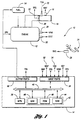
- FIG. 1 provides a block diagram illustrating operation of a system or method for providing smooth transitions between mode controllers according to the present invention.
- System 10 includes an internal combustion engine, indicated generally by reference numeral 12, in communication with a controller 14.
- Various sensors are provided to monitor engine operating conditions. Sensors may include a mass air flow sensor (MAF) 16 which monitors the air passing through intake 18.
- a throttle valve 20 regulates the air intake into engine 12 as well known in the art.
- a throttle position sensor (TPS) 22 provides an appropriate signal to controller 14 to monitor the throttle angle or position of throttle valve 20.
- An appropriate actuator such as a mechanical or electronic accelerator pedal 24 is used to determine the driver demand which, in turn, is used in the control of the position of throttle valve 20.
- system 10 is an electronic throttle control system which uses a pedal position sensor (PPS) 26 to provide a signal indicative of the position of an accelerator pedal 24.
- Controller 14 uses the pedal position sensor signal, along with various other signals indicative of current engine operating conditions, to control the position of throttle valve 20 via an appropriate servo motor or other actuator 23.
- PPS pedal position sensor
- Such electronic throttle control or "drive-by-wire" systems are well known in the art.
- Engine 12 may include various other sensors such as an engine speed sensor (RPM) 28, an engine temperature or coolant temperature sensor (TMP) 30, a manifold absolute pressure (MAP) sensor 32, a vehicle speed sensor (VSS) 34, and the like.
- RPM engine speed sensor
- TMP engine temperature or coolant temperature sensor
- MAP manifold absolute pressure
- VSS vehicle speed sensor
- Processor 14 receives signals from the various sensors via input ports 36 which may provide signal conditioning, conversion, and/or fault detection, as well known in the art.
- Input port 36 communicates with processor 38 via a data/control bus 40.
- Processor 38 implements control logic in the form of hardware and/or software instructions which may be stored in computer-readable media 42 to effect control of engine 12.
- Computer-readable media 42 may include various types of volatile and non-volatile memory such as random-access memory (RAM) 44, read-only memory (ROM) 46, and keep-alive memory (KAM) 48. These "functional" classifications of memory may be implemented by one or more different physical devices such as PROMs, EPROMs, EEPROMs, flash memory, and the like, depending upon the particular application.
- processor 38 executes instructions stored in computer-readable media 42 to carry out a method for controlling engine 12 using at least two mode controllers implemented in software and/or hardware to communicate with various actuators of engine 12 via output port 50.
- Actuators may control ignition timing or spark (SPK) 52, timing and metering of fuel 54, or position of throttle valve 20 to control air flow.
- Electronic control of air flow may also be performed using variable cam timing, for example.
- controller 14 is used to implement at least two mode controllers which provide idle speed control and torque-based engine control depending upon the particular mode of operation of engine 12.
- FIG. 2 is a block diagram illustrating representative mode controllers for idle speed control and engine torque control according to the present invention.
- Idle speed controller 60 and engine torque controller are preferably implemented within a powertrain control module or controller 14.
- the present invention is generally applicable to any control system having disparate mode controllers where control passes between mode controllers during operation.
- the present invention could also be applied to a throttle angle/throttle follower based control system architecture where interpreted driver demand corresponds to a throttle valve position or angle.
- the present invention provides a trim value or correction value to the input of a first controller based on the difference in outputs of the first and second controllers to provide a smooth transition between controllers.
- the correction value is generated by a third feedback controller 64 which is selectively activated to drive the difference or error between outputs of the first and second controllers toward zero.
- idle speed controller 60 generates a desired air flow (DESMAF) based on a desired engine speed (RPMDES).
- engine torque controller 62 generates a desired air flow (TQ_DESMAF) based on a desired total engine torque (TQ_ENG_TOT).
- the outputs from idle speed controller 60 and torque controller 62 are switched or multiplexed based on the accelerator pedal position as represented by block 84.
- a status indicator (APP) indicates whether the accelerator pedal is fully released, partly depressed, or fully depressed.
- Idle speed controller 60 is activated or active when the APP flag indicates that the throttle pedal is fully released. Otherwise, engine torque controller 62 is active.
- Block 66 selects the larger value of the output from block 64 and idle speed controller 60. The resulting air flow is converted to a desired throttle position and used to control the throttle valve.
- idle speed controller 60 also includes a dashpot control mode to control the rate of engine deceleration whenever engine speed is significantly above the idle speed and the accelerator pedal is fully released.
- controller 64 is a proportional-integral (PI) controller which updates its output only when the APP status flag indicates that the accelerator pedal is not being depressed.
- PI proportional-integral
- the controller drives the control output continuously to provide a zero steady state error and quickly responds to changes in the error signal without objectionable oscillation or overshoot.
- the output of the proportional block 70 and integral block 72 is combined at block 74. This control output is then converted from units of air flow to a unitless load at block 76.
- this is accomplished by dividing by the number of cylinders per minute (engine speed times cylinders divided by 2), and then dividing by the standard temperature air charge per cylinder, which depends on the per cylinder displacement of the engine.
- the result from block 76 is multiplied by a load-to-engine torque normaliser at block 78 to convert the unitless quantity to a torque.
- the output of block 78 is multiplied by a final gain at block 80 to provide the necessary correction value based on the air mass error.
- the gain provided by block 80 could be incorporated into controller 64 or block 78, but is provided for ease of calibration and tuning.
- the resulting correction value from block 80 is combined with the engine torque request (TQ_ENG_LOAD) at block 82.
- Figures 3a and 3b provide a graphical representation of a jittery transition between mode controllers without the benefit of the present invention.
- Figure 3a represents the requested engine torque 90 as a function of time.
- Figure 3b represents the requested or desired air flow from the idle speed controller 92, the engine torque controller 94, and the resulting final torque 96 based on the active controller.
- the accelerator pedal is fully released and the idle speed controller is active.
- the driver demanded air flow 94 is greater than the idle speed control air flow 92 which is collinear with the final air flow 96.
- the accelerator pedal begins to be depressed at tine t 2 .
- the active controller transitions from the idle speed controller to the engine torque controller resulting in jitter of the final commanded air flow 96.
- Figures 4a and 4b are graphs illustrating a sluggish or "dead pedal" transition between mode controllers without the benefit of the present invention.
- the air flow requested from the idle speed controller 92 exceeds the driver demanded air flow 94 at time t 1 when the idle speed controller is active.
- the accelerator pedal is depressed and the engine torque controller becomes the active controller.
- the air flow requested from the idle speed controller exceeds that of the engine torque controller, and therefore controls the final commanded air flow 96.
- the final commanded air flow remains at the same level and there is no increase in the resulting engine torque even though the accelerator pedal is being depressed.
- the final commanded air flow does not begin to actually increase until the accelerator pedal is depressed to a point represented as time t 3 resulting in a "dead pedal" feel, i.e. no increase in engine torque in response to an increase in the accelerator pedal position.
- Figures 5a and 5b provide graphs illustrating a smooth transition between mode controllers according to the present invention.
- Figure 5a illustrates operation of the correction value according to the present invention.
- the correction value represented generally by line 100
- the resulting requested torque is represented by line 104.
- the total requested torque shows a smooth transition when the final commanded air flow transitions from the idle speed controller to the engine torque controller.
- air flow requested by the idle speed controller represented by line 92
- the correction value feedback controller generates a correction value 100 which is added to the input of the engine torque controller to increase the requested air flow 94.
- the air flows requested by the idle speed controller and the engine torque controller are approximately equal at time t 2 .
- the accelerator pedal is depressed at time t 3 , a smooth, seamless transition between mode controllers results.
- the correction value is preferably added to the input of the engine torque controller.
- this technique provides a correction that represents an actual torque. This is advantageous in that the engine torque controller assumes that the requested torque is the total engine load for the purpose of calibration of various other control parameters including spark, EGR, and pumping losses which will result. If the idle air flow were simply added to the engine torque requested air flow, the resulting load would be higher than expected by the torque-to-load calculation, resulting in unsatisfactory performance.
- Providing the correction value to the input of the engine torque controller provides a more robust control of engine torque and smooth transitions between the idle/dashpot controller and the engine torque controller.
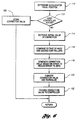
- control logic for providing smooth transitions between mode controllers in a system or method according to the present invention is shown.
- control logic may be implemented in software, hardware, or a combination of software and hardware.
- various processing strategies may be utilised without departing from the spirit or scope of the present invention.
- most real-time control strategies utilise event-driven or interrupt-driven processing.
- sequence of operations illustrated is not necessarily required to accomplish the advantages of the present invention, and is provided for ease of illustration only.
- various steps may be performed in parallel or by dedicated electric or electronic circuits.
- Block 110 represents determination of the accelerator pedal position for an electronic throttle control application.
- the accelerator pedal position may be used by block 112 to determine which controller is active.
- various other inputs may also be utilised to determine the active mode controller, such as the status of the cruise control or various other engine operating parameters.
- an initial value for the correction term is retrieved from storage as indicated by block 114.
- the outputs from the first and second controllers are compared to generate an error signal as represented by block 116.
- the error signal is used to generate a correction value which is preferably feedback-controlled to reduce the error toward zero as represented by block 118.
- the correction value is converted to the proper parameters or units as indicated by block 120.
- the correction value may also be normalised, if desired, as described in greater detail above.
- block 120 converts an air flow error to a correction value in units of torque.
- the correction value is then provided to one of the controllers as represented by block 122.
- the previously generated correction value if any, is stored for future retrieval as represented by block 124.
- This step is performed in a preferred embodiment to prevent excessive integrator wind-up in the PI feedback controller. Depending upon the particular feedback controller, if any, this step may not be necessary.
Landscapes
- Engineering & Computer Science (AREA)
- Chemical & Material Sciences (AREA)
- Combustion & Propulsion (AREA)
- Mechanical Engineering (AREA)
- General Engineering & Computer Science (AREA)
- Electrical Control Of Air Or Fuel Supplied To Internal-Combustion Engine (AREA)
- Combined Controls Of Internal Combustion Engines (AREA)
Applications Claiming Priority (2)
| Application Number | Priority Date | Filing Date | Title |
|---|---|---|---|
| US09/307,449 US6119063A (en) | 1999-05-10 | 1999-05-10 | System and method for smooth transitions between engine mode controllers |
| US307449 | 1999-05-10 |
Publications (2)
| Publication Number | Publication Date |
|---|---|
| EP1052390A2 true EP1052390A2 (de) | 2000-11-15 |
| EP1052390A3 EP1052390A3 (de) | 2002-06-12 |
Family
ID=23189824
Family Applications (1)
| Application Number | Title | Priority Date | Filing Date |
|---|---|---|---|
| EP00303144A Withdrawn EP1052390A3 (de) | 1999-05-10 | 2000-04-13 | Vorrichtung und Verfahren für das Verbessern von Übergängen zwischen Motorbetriebsarten |
Country Status (2)
| Country | Link |
|---|---|
| US (1) | US6119063A (de) |
| EP (1) | EP1052390A3 (de) |
Cited By (3)
| Publication number | Priority date | Publication date | Assignee | Title |
|---|---|---|---|---|
| EP1630391A1 (de) * | 2004-08-27 | 2006-03-01 | Siemens Aktiengesellschaft | Vefahren und Vorrichtung zur Ermittlung eines Ausgabedrehmoments |
| EP1277940A3 (de) * | 2001-07-19 | 2006-05-03 | Robert Bosch Gmbh | Verfahren und Vorrichtung zum Betreiben eines Antriebmotors |
| EP3045703A1 (de) * | 2015-01-14 | 2016-07-20 | Toyota Jidosha Kabushiki Kaisha | Steuerungsvorrichtung für verbrennungsmotor |
Families Citing this family (24)
| Publication number | Priority date | Publication date | Assignee | Title |
|---|---|---|---|---|
| US6425373B1 (en) * | 1999-08-04 | 2002-07-30 | Ford Global Technologies, Inc. | System and method for determining engine control parameters based on engine torque |
| US6220226B1 (en) * | 1999-10-15 | 2001-04-24 | Volvo Lastvagnar Ab | Method of controlling changes in torque in an internal combustion engine and an internal combustion engine controlled in accordance with said method |
| US6371081B1 (en) * | 2000-09-29 | 2002-04-16 | Detroit Diesel Corporation | Inhibit engine speed governor |
| JP2002276447A (ja) * | 2001-03-19 | 2002-09-25 | Denso Corp | 内燃機関の制御装置 |
| US6659080B2 (en) * | 2001-07-26 | 2003-12-09 | General Motors Corporation | Methods and apparatus for adjusting a throttle of a vehicle engine |
| US6718255B1 (en) | 2002-10-04 | 2004-04-06 | Ford Global Technologies, Llc | Method and system for matching engine torque transitions between closed and partially closed accelerator pedal positions |
| US6770009B2 (en) * | 2002-12-16 | 2004-08-03 | Ford Global Technologies, Llc | Engine speed control in a vehicle during a transition of such vehicle from rest to a moving condition |
| US6754578B1 (en) * | 2003-03-27 | 2004-06-22 | Ford Global Technologies, Llc | Computer instructions for control of multi-path exhaust system in an engine |
| US6877480B2 (en) | 2003-09-05 | 2005-04-12 | Ford Global Technologies, Llc | Idle speed compensation in a pedal map |
| US6953023B2 (en) * | 2003-09-05 | 2005-10-11 | Ford Global Technologies, Llc | Acceleration pedal interpretation when engine torque is limited |
| GB2412448B (en) * | 2004-03-22 | 2008-05-28 | Ford Global Tech Llc | Powertrain control systems |
| US6990953B2 (en) * | 2004-05-24 | 2006-01-31 | Nissan Motor Co., Ltd. | Idle rotation control of an internal combustion engine |
| US7111611B1 (en) | 2005-09-21 | 2006-09-26 | Daimlerchrysler Corporation | Torque sensor-based engine and powertrain control system |
| US7275518B1 (en) | 2006-04-28 | 2007-10-02 | Ford Global Technologies, Llc | Torque-based powertrain control for vehicles |
| US7571635B2 (en) * | 2007-05-02 | 2009-08-11 | Chrysler Group Llc | Engine knock detection system and method |
| KR100941714B1 (ko) * | 2007-11-07 | 2010-02-12 | 현대자동차주식회사 | 엔진의 토크 제어장치 및 방법 |
| US8302397B2 (en) * | 2009-08-11 | 2012-11-06 | GM Global Technology Operations LLC | Mode transition systems and methods for a sequential turbocharger |
| DE102010040279A1 (de) * | 2010-09-06 | 2012-03-08 | Robert Bosch Gmbh | Verfahren und Vorrichtung zum Betreiben einer Antriebseinheit eines Kraftfahrzeuges |
| JP5641960B2 (ja) * | 2011-02-01 | 2014-12-17 | 三菱電機株式会社 | 内燃機関の制御装置 |
| US9435271B2 (en) * | 2011-10-12 | 2016-09-06 | Ford Global Technologies, Llc | Methods and systems for controlling airflow through a throttle turbine generator |
| DE102013205936B4 (de) | 2013-04-04 | 2016-07-14 | TRUMPF Hüttinger GmbH + Co. KG | Verfahren zur Regelung einer Regelstrecke mit normierter Auswahlgröße |
| GB2526357B (en) * | 2014-05-23 | 2018-05-30 | Jaguar Land Rover Ltd | Speed control system and method having predetermined speed profile which is suspended on powertrain torque supply interruption |
| US9623866B2 (en) | 2015-05-15 | 2017-04-18 | Ford Global Technologies, Llc | Methods and systems for selectively adapting engine air flow |
| US10196066B2 (en) | 2016-01-11 | 2019-02-05 | Cnh Industrial America Llc | Automotive productivity manager for power shift transmissions |
Family Cites Families (53)
| Publication number | Priority date | Publication date | Assignee | Title |
|---|---|---|---|---|
| DE2811574A1 (de) * | 1978-03-17 | 1979-09-27 | Bosch Gmbh Robert | Vorrichtung zur regelung einer antriebsmotor-getriebe-einheit eines kraftfahrzeuges |
| JPS56107925A (en) * | 1980-01-31 | 1981-08-27 | Mikuni Kogyo Co Ltd | Electronically controlled fuel injector for ignited internal combustion engine |
| JPS6034563A (ja) * | 1983-08-05 | 1985-02-22 | Nippon Soken Inc | 自動車用自動変速制御装置 |
| JPS60164632A (ja) * | 1984-02-07 | 1985-08-27 | Nissan Motor Co Ltd | 自動車の電子制御装置 |
| US4509478A (en) * | 1984-06-11 | 1985-04-09 | General Motors Corporation | Engine fuel control system |
| JPS61145340A (ja) * | 1984-12-20 | 1986-07-03 | Honda Motor Co Ltd | 内燃エンジンのアイドル回転数フイ−ドバツク制御方法 |
| US4697561A (en) * | 1985-04-15 | 1987-10-06 | Purdue Research Foundation | On-line engine torque and torque fluctuation measurement for engine control utilizing crankshaft speed fluctuations |
| US4730708A (en) * | 1985-05-30 | 1988-03-15 | Toyota Jidosha Kabushiki Kaisha | Idling control method and system for internal combustion engine providing anti creep action |
| US4760823A (en) * | 1985-06-24 | 1988-08-02 | Honda Giken Kogyo Kabushiki Kaisha | Method for control of idle rotations of internal combustion engine |
| JPH0792141B2 (ja) * | 1988-05-06 | 1995-10-09 | 日産自動車株式会社 | 自動変速機のライン圧制御装置 |
| JPH0281939A (ja) * | 1988-09-16 | 1990-03-22 | Mazda Motor Corp | 自動変速機付車両におけるエンジンの吸入空気量制御装置 |
| JPH0660678B2 (ja) * | 1988-10-29 | 1994-08-10 | マツダ株式会社 | 自動変速機のライン圧制御装置 |
| WO1990008889A1 (fr) * | 1989-01-31 | 1990-08-09 | Mitsubishi Jidosha Kogyo Kabushiki Kaisha | Regulateur de sortie pour moteur a combustion interne |
| WO1990008888A1 (fr) * | 1989-01-31 | 1990-08-09 | Mitsubishi Jidosha Kogyo Kabushiki Kaisha | Commande de puissance de moteurs |
| US5078109A (en) * | 1989-01-31 | 1992-01-07 | Mitsubishi Jidosha Kogyo Kabushiki Kaisha | Engine output controlling method |
| JP2510304B2 (ja) * | 1989-12-15 | 1996-06-26 | 日産自動車株式会社 | 自動変速機の作動油圧制御装置 |
| US5044457A (en) * | 1989-12-15 | 1991-09-03 | Aikman Steven W | Motor vehicle cruise control system having mode dependent gain |
| JP2510305B2 (ja) * | 1989-12-19 | 1996-06-26 | 日産自動車株式会社 | 自動変速機の作動油圧制御装置 |
| DE4037237A1 (de) * | 1990-11-23 | 1992-05-27 | Bosch Gmbh Robert | Verfahren zum betreiben einer aus brennkraftmaschine und automatischem getriebe bestehenden antriebseinheit |
| US5304102A (en) * | 1991-02-21 | 1994-04-19 | Nissan Motor Co., Ltd. | Control for shift in automatic transmission |
| DE4111023C2 (de) * | 1991-04-05 | 2003-11-20 | Bosch Gmbh Robert | Elektronisches System für ein Fahrzeug |
| DE4210956A1 (de) * | 1991-08-02 | 1993-02-04 | Bosch Gmbh Robert | Einrichtung zur steuerung der ausgangsleistung einer antriebseinheit eines fahrzeugs |
| DE4141947C2 (de) * | 1991-12-19 | 2002-02-07 | Bosch Gmbh Robert | Steuersystem für eine Antriebseinheit in einem Flugzeug |
| DE4204401A1 (de) * | 1992-02-14 | 1993-08-19 | Bosch Gmbh Robert | Einrichtung zur steuerung des abtriebsmoments eines automatischen schaltgetriebes |
| DE4304779B4 (de) * | 1992-06-20 | 2005-11-24 | Robert Bosch Gmbh | Vorrichtung zur Steuerung des von einer Antriebseinheit eines Fahrzeugs abzugebenden Drehmoments |
| KR100298250B1 (ko) * | 1992-09-16 | 2001-10-24 | 가나이 쓰도무 | 차량용구동력제어장치 |
| DE4235827B4 (de) * | 1992-10-23 | 2013-05-08 | Robert Bosch Gmbh | Verfahren und Einrichtung zur Steuerung der Ausgangsleistung einer Antriebseinheit eines Fahrzeugs |
| DE4311921A1 (de) * | 1993-04-10 | 1994-10-13 | Bosch Gmbh Robert | Verfahren zur Betätigung eines automatischen Getriebes |
| BR9407115A (pt) * | 1993-06-30 | 1996-09-03 | Orbital Eng Pty | Sistemas de suprimentro de ar de motor |
| DE4329978A1 (de) * | 1993-09-04 | 1995-03-09 | Bosch Gmbh Robert | Verfahren und Vorrichtung zur Betätigung eines selbständig schaltenden Getriebes |
| DE4333899A1 (de) * | 1993-10-05 | 1995-07-13 | Bosch Gmbh Robert | Verfahren zur Steuerung des Abtriebsmoments eines automatischen Schaltgetriebes |
| DE4343353C2 (de) * | 1993-12-18 | 2002-12-05 | Bosch Gmbh Robert | Verfahren und Vorrichtung zum Steuern einer Brennkraftmaschine |
| US5431139A (en) * | 1993-12-23 | 1995-07-11 | Ford Motor Company | Air induction control system for variable displacement internal combustion engine |
| US5374224A (en) * | 1993-12-23 | 1994-12-20 | Ford Motor Company | System and method for controlling the transient torque output of a variable displacement internal combustion engine |
| US5408974A (en) * | 1993-12-23 | 1995-04-25 | Ford Motor Company | Cylinder mode selection system for variable displacement internal combustion engine |
| US5398544A (en) * | 1993-12-23 | 1995-03-21 | Ford Motor Company | Method and system for determining cylinder air charge for variable displacement internal combustion engine |
| US5408966A (en) * | 1993-12-23 | 1995-04-25 | Ford Motor Company | System and method for synchronously activating cylinders within a variable displacement engine |
| DE4407475C2 (de) * | 1994-03-07 | 2002-11-14 | Bosch Gmbh Robert | Verfahren und Vorrichtung zur Steuerung eines Fahrzeugs |
| US5445125A (en) * | 1994-03-16 | 1995-08-29 | General Motors Corporation | Electronic throttle control interface |
| JP3535233B2 (ja) * | 1994-10-18 | 2004-06-07 | ヤマハマリン株式会社 | 船外機用2サイクルエンジンの運転制御装置 |
| US5520159A (en) * | 1994-12-09 | 1996-05-28 | Ford Motor Company | Burned gas recycling system with powertrain optimization |
| DE19502150C1 (de) * | 1995-01-25 | 1996-05-23 | Bosch Gmbh Robert | System zur Regelung der Aufladung einer Brennkraftmaschine |
| JP3573368B2 (ja) * | 1995-02-21 | 2004-10-06 | 本田技研工業株式会社 | 車両のエンジン出力制御装置 |
| DE19517434B4 (de) * | 1995-05-12 | 2006-08-10 | Robert Bosch Gmbh | Verfahren zur Unterbrechung der Kraftstoffzufuhr im Schiebebetrieb einer Brennkraftmaschine |
| US5503129A (en) * | 1995-05-18 | 1996-04-02 | Ford Motor Company | Apparatus and method for mode recommendation in a variable displacement engine |
| US5568795A (en) * | 1995-05-18 | 1996-10-29 | Ford Motor Company | System and method for mode selection in a variable displacement engine |
| US5588178A (en) * | 1995-06-07 | 1996-12-31 | Mcculloch Corporation | Impeller for blower/vacuum |
| US5646851A (en) * | 1995-06-30 | 1997-07-08 | Saturn Corporation | Integrated engine control |
| AUPN716795A0 (en) * | 1995-12-15 | 1996-01-18 | Orbital Engine Company (Australia) Proprietary Limited | Control of fuelling |
| GB2312970A (en) * | 1996-05-11 | 1997-11-12 | Ford Motor Co | Diesel engine control |
| SE522177C2 (sv) * | 1996-08-27 | 2004-01-20 | Mitsubishi Motors Corp | Styranordning för en förbränningsmotor med cylinderinsprutning och gnisttändning |
| JP3710073B2 (ja) * | 1997-03-31 | 2005-10-26 | 三菱自動車工業株式会社 | 吸気絞り弁制御装置 |
| US5901682A (en) * | 1997-12-19 | 1999-05-11 | Caterpillar Inc. | Method for transitioning between different operating modes of an internal combustion engine |
-
1999
- 1999-05-10 US US09/307,449 patent/US6119063A/en not_active Expired - Fee Related
-
2000
- 2000-04-13 EP EP00303144A patent/EP1052390A3/de not_active Withdrawn
Cited By (5)
| Publication number | Priority date | Publication date | Assignee | Title |
|---|---|---|---|---|
| EP1277940A3 (de) * | 2001-07-19 | 2006-05-03 | Robert Bosch Gmbh | Verfahren und Vorrichtung zum Betreiben eines Antriebmotors |
| EP1630391A1 (de) * | 2004-08-27 | 2006-03-01 | Siemens Aktiengesellschaft | Vefahren und Vorrichtung zur Ermittlung eines Ausgabedrehmoments |
| EP3045703A1 (de) * | 2015-01-14 | 2016-07-20 | Toyota Jidosha Kabushiki Kaisha | Steuerungsvorrichtung für verbrennungsmotor |
| CN105781763A (zh) * | 2015-01-14 | 2016-07-20 | 丰田自动车株式会社 | 用于内燃机的控制设备 |
| CN105781763B (zh) * | 2015-01-14 | 2019-03-12 | 丰田自动车株式会社 | 用于内燃机的控制设备 |
Also Published As
| Publication number | Publication date |
|---|---|
| EP1052390A3 (de) | 2002-06-12 |
| US6119063A (en) | 2000-09-12 |
Similar Documents
| Publication | Publication Date | Title |
|---|---|---|
| US6119063A (en) | System and method for smooth transitions between engine mode controllers | |
| US8566008B2 (en) | Control device for internal combustion engine | |
| EP2317106B1 (de) | Steuervorrichtung für einen verbrennungsmotor | |
| US6688282B1 (en) | Power-based idle speed control | |
| JP6041050B2 (ja) | 内燃機関の制御装置 | |
| US9341125B2 (en) | Engine control apparatus and engine control method | |
| US6246951B1 (en) | Torque based driver demand interpretation with barometric pressure compensation | |
| WO2014184871A1 (ja) | 内燃機関の制御装置 | |
| US20110132324A1 (en) | Linear tranformation engine torque control systems and methods for increasing torque requests | |
| EP1380744B1 (de) | Maschine mit Momentsteuerung | |
| US20150159546A1 (en) | Control device of internal combustion engine equipped with turbo supercharger | |
| US6718255B1 (en) | Method and system for matching engine torque transitions between closed and partially closed accelerator pedal positions | |
| US6449553B1 (en) | Motor vehicle control device with regulation and/or limitation of driving speed | |
| JP4835456B2 (ja) | 内燃機関の制御装置 | |
| CN1302346C (zh) | 用于控制内燃机的方法和装置 | |
| US6314359B1 (en) | System for modifying a load bias function based on transient engine operation | |
| JP2000008962A (ja) | 内燃機関のアクチュエータ制御装置 | |
| CN107795372B (zh) | 用于废气门控制的方法和系统 | |
| JP5920176B2 (ja) | 内燃機関の制御装置 | |
| JPH10325348A (ja) | エンジンのアイドル回転数制御装置 | |
| CN119895133A (zh) | 控制氢内燃机的方法 | |
| JP4379098B2 (ja) | 内燃機関の制御装置 | |
| CN101680384B (zh) | 内燃机的控制装置 | |
| CN103415688A (zh) | 用于调节内燃机的方法 | |
| JP2009228481A (ja) | エンジンの制御装置 |
Legal Events
| Date | Code | Title | Description |
|---|---|---|---|
| PUAI | Public reference made under article 153(3) epc to a published international application that has entered the european phase |
Free format text: ORIGINAL CODE: 0009012 |
|
| AK | Designated contracting states |
Kind code of ref document: A2 Designated state(s): AT BE CH CY DE DK ES FI FR GB GR IE IT LI LU MC NL PT SE |
|
| AX | Request for extension of the european patent |
Free format text: AL;LT;LV;MK;RO;SI |
|
| PUAL | Search report despatched |
Free format text: ORIGINAL CODE: 0009013 |
|
| AK | Designated contracting states |
Kind code of ref document: A3 Designated state(s): AT BE CH CY DE DK ES FI FR GB GR IE IT LI LU MC NL PT SE |
|
| AX | Request for extension of the european patent |
Free format text: AL;LT;LV;MK;RO;SI |
|
| 17P | Request for examination filed |
Effective date: 20021030 |
|
| AKX | Designation fees paid |
Designated state(s): DE GB SE |
|
| STAA | Information on the status of an ep patent application or granted ep patent |
Free format text: STATUS: THE APPLICATION HAS BEEN WITHDRAWN |
|
| 17Q | First examination report despatched |
Effective date: 20050406 |
|
| 18W | Application withdrawn |
Effective date: 20050422 |