EP1052446A2 - Projecteur pour véhicules - Google Patents
Projecteur pour véhicules Download PDFInfo
- Publication number
- EP1052446A2 EP1052446A2 EP00109699A EP00109699A EP1052446A2 EP 1052446 A2 EP1052446 A2 EP 1052446A2 EP 00109699 A EP00109699 A EP 00109699A EP 00109699 A EP00109699 A EP 00109699A EP 1052446 A2 EP1052446 A2 EP 1052446A2
- Authority
- EP
- European Patent Office
- Prior art keywords
- shaft
- diaphragm shaft
- reflector
- drive means
- headlight according
- Prior art date
- Legal status (The legal status is an assumption and is not a legal conclusion. Google has not performed a legal analysis and makes no representation as to the accuracy of the status listed.)
- Granted
Links
- 230000005540 biological transmission Effects 0.000 claims description 7
- 230000003287 optical effect Effects 0.000 claims description 6
- 241000219739 Lens Species 0.000 description 10
- 240000004322 Lens culinaris Species 0.000 description 1
- 230000000903 blocking effect Effects 0.000 description 1
- 230000001788 irregular Effects 0.000 description 1
- 239000002184 metal Substances 0.000 description 1
- 229910001092 metal group alloy Inorganic materials 0.000 description 1
Images


Classifications
-
- F—MECHANICAL ENGINEERING; LIGHTING; HEATING; WEAPONS; BLASTING
- F21—LIGHTING
- F21S—NON-PORTABLE LIGHTING DEVICES; SYSTEMS THEREOF; VEHICLE LIGHTING DEVICES SPECIALLY ADAPTED FOR VEHICLE EXTERIORS
- F21S41/00—Illuminating devices specially adapted for vehicle exteriors, e.g. headlamps
- F21S41/60—Illuminating devices specially adapted for vehicle exteriors, e.g. headlamps characterised by a variable light distribution
- F21S41/68—Illuminating devices specially adapted for vehicle exteriors, e.g. headlamps characterised by a variable light distribution by acting on screens
- F21S41/683—Illuminating devices specially adapted for vehicle exteriors, e.g. headlamps characterised by a variable light distribution by acting on screens by moving screens
- F21S41/698—Shaft-shaped screens rotating along its longitudinal axis
-
- F—MECHANICAL ENGINEERING; LIGHTING; HEATING; WEAPONS; BLASTING
- F21—LIGHTING
- F21S—NON-PORTABLE LIGHTING DEVICES; SYSTEMS THEREOF; VEHICLE LIGHTING DEVICES SPECIALLY ADAPTED FOR VEHICLE EXTERIORS
- F21S41/00—Illuminating devices specially adapted for vehicle exteriors, e.g. headlamps
- F21S41/50—Illuminating devices specially adapted for vehicle exteriors, e.g. headlamps characterised by aesthetic components not otherwise provided for, e.g. decorative trim, partition walls or covers
- F21S41/55—Attachment thereof
Definitions
- the invention relates to headlights for vehicles with a cup-shaped Reflector, with a light source assigned to the reflector, with a between a lens and the reflector arranged aperture shaft, with one with the Aperture shaft coupled drive means through which the aperture shaft by one horizontal and perpendicular to the optical axis of rotation in several Rotational positions is adjustable, and with one the aperture shaft and that Holder carrying drive means.
- Such a headlight for vehicles is known from DE 43 35 286 A1.
- On Light module of the headlight has an ellipsoidal reflector, one in the Beam path of the reflector and a lens arranged between the reflector and Lens inserted lens.
- the outer surface of the diaphragm shaft points for each rotational position of the diaphragm shaft on an aperture line, which a Light-dark boundary generated by a light figure.
- the aperture wave runs between two legs of a U-shaped holder and engages in bearing openings of the legs on.
- a drive means of the diaphragm shaft has an electric motor and Gearbox, which couples the aperture shaft with the gearbox.
- the engine is attached to the outside of one leg of the U-shaped holder and leads with it Drive shaft through an opening of the leg of the holder. This through the opening protruding end of the diaphragm shaft is via the gearbox with the Aperture shaft coupled.
- the gearbox consists of two gears, one of which one sits on the aperture shaft and the other sits on the drive shaft of the engine. It is disadvantageous here that the holder is composed of several parts and light rays of the light source reflected by the reflector through the Can pass through the U-shaped holder and dazzle oncoming traffic.
- the object of the invention is to design the headlights for vehicles described in the preamble of claim 1 such that the light rays of the light source are shielded below the aperture shaft and the holder consists of as few parts as possible.
- This object is achieved according to the invention in that a shader arranged below the diaphragm shaft is the holder for the diaphragm shaft and the drive means, the diaphragm shaft being arranged with a section in an upwardly open receiving groove of the shader and the shading device on the side of its receiving groove being a receiving element for the drive means.
- the shading device and the diaphragm shaft together shield light rays from the light source assigned to the reflector, and the shading device is stiffened by the receiving channel.
- the shader is heat-resistant if it consists of a cast metal alloy. In addition, it guides the inside of the headlight over the receiving element or a light module of the headlamp from the heat generated to the outside.
- the aperture shaft and the shader are also lightproof together if the receiving channel is caused by a irregular shape of the diaphragm shaft a greater distance from the diaphragm shaft having.
- the shader has a high one in the area holding the diaphragm shaft Stiffness when the receiving channel is limited in its length by side walls is introduced into the bearing openings for the diaphragm shaft.
- a smooth one Swiveling of the diaphragm shaft is guaranteed when in the bearing openings respectively a sliding sleeve is used for the journal of the diaphragm shaft.
- the receiving element for the drive means forms together with the shader a stable unit if the receiving element is connected to a side wall through the Side walls stiffened receiving channel is attached.
- the drive means is arranged on the headlamp to save space if that Receiving element in its main dimension transverse to the axis of rotation of the Aperture shaft runs and points towards the back of the headlight, with a Electric motor of the drive means on the side of the reflector facing Receiving element is arranged and the electric motor via a gearbox Drive means is coupled to the aperture shaft.
- the electric motor builds not on the side, since it is adjacent to the back of the headlight tapered reflector is arranged.
- the gear is arranged protected when the receiving element is a housing part for the transmission. This prevents objects such as Example electrical cables that can get between the gear wheels of the transmission and thus blocking the function of the electric drive.
- the housing part can be completed by a removable housing cover.
- the shader forms one together with its receiving channel torsionally stiff holder when the shader angled edge sections having.
- the invention is on the inside the receiving channel attached at least one stop for the diaphragm shaft.
- the Stop is used to adjust the aperture shaft and can be made in one piece with the Shadows are executed.
- a shader with two stops can also other headlight variants with different aperture shafts are used become.
- the headlight for vehicles has a light module, which is not in a shown headlight housing can be used.
- the light module is in the Headlight housing pivoted about at least one axis and is used for Generation of different dimmed light beams.
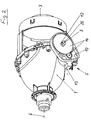
- the light module has an ellipsoidal reflector 1, in the latter Apex region an opening for receiving a light source 2 is introduced.
- the light source can be an incandescent lamp or a gas discharge lamp.
- To the front edge of the reflector 1 is attached to a frame 18 made of sheet metal.
- the frame 18 accommodates a lens 3 in a central opening
- a shader 8 is arranged below an optical axis 6 of the reflector 1.
- the shader 8 runs with a plate-shaped section vertically and transversely optical axis 6.
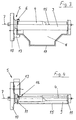
- the plate-shaped section of the shader 8 is with its outer edge, which has angled edge portions 17 towards the lens 3 attached to the front edge of the reflector 1. Above the plate-shaped Section, the shader 8 has a receiving groove 9 for the diaphragm shaft 4.
- the receiving channel 4 extends from the plate-shaped section on the side of the diaphragm shaft 4 facing the lens 3.
- the receiving groove 9 extends with its upper edge to the optical axis 6 of the reflector 1 and surrounds the aperture shaft 4 at a distance.
- the receiving channel 9 points to both Ends formed on side walls 11, in which bearing openings 12 for Bearing journals 20 of the aperture shaft 4 are introduced.
- bearing openings 12 are Sliding sleeves 19 used.
- the aperture shaft 4 points for at least two Rotational positions another aperture line, which to generate a The light-dark boundary of a dimmed light beam is used.
- To one of the two Side walls 11 of the receiving channel 9 is a receiving element 10 for an outside Drive means 5 integrally formed.
- the receiving element 10 is plate-shaped and runs transversely to the axis of rotation 7 of the diaphragm shaft 4. Through an opening of the Receiving element 10 projects through one of the journals 20 of the diaphragm shaft 4.
- the bearing pin 20 engages in an opening of a large gear of a transmission 14 a.
- the large gear meshes with its teeth in the teeth of a small one Gear of the transmission 14. Both gears lie with their large ones Side surfaces on the plate-shaped receiving element 10.
- the gears of the Gear 14 are in a laterally open housing of the receiving element 10 arranged.
- the receiving element 10 extends to the rear of the Headlights out and carries on the bowl-shaped reflector 1 Side an electric motor 13 of the drive means 5.
- the motor 13 is over his Drive shaft connected to the small gear of the transmission 14.
- On one of the Both side walls 11 of the receiving channel 9 is above the aperture shaft 4 stop 16 for adjustment and calibration of the diaphragm shaft appropriate.
Landscapes
- Engineering & Computer Science (AREA)
- General Engineering & Computer Science (AREA)
- Non-Portable Lighting Devices Or Systems Thereof (AREA)
- Lighting Device Outwards From Vehicle And Optical Signal (AREA)
Applications Claiming Priority (2)
| Application Number | Priority Date | Filing Date | Title |
|---|---|---|---|
| DE19921907 | 1999-05-12 | ||
| DE19921907A DE19921907A1 (de) | 1999-05-12 | 1999-05-12 | Scheinwerfer für Fahrzeuge |
Publications (3)
| Publication Number | Publication Date |
|---|---|
| EP1052446A2 true EP1052446A2 (fr) | 2000-11-15 |
| EP1052446A3 EP1052446A3 (fr) | 2002-03-13 |
| EP1052446B1 EP1052446B1 (fr) | 2004-02-25 |
Family
ID=7907840
Family Applications (1)
| Application Number | Title | Priority Date | Filing Date |
|---|---|---|---|
| EP00109699A Expired - Lifetime EP1052446B1 (fr) | 1999-05-12 | 2000-05-08 | Projecteur pour véhicules |
Country Status (2)
| Country | Link |
|---|---|
| EP (1) | EP1052446B1 (fr) |
| DE (2) | DE19921907A1 (fr) |
Cited By (6)
| Publication number | Priority date | Publication date | Assignee | Title |
|---|---|---|---|---|
| WO2005024296A1 (fr) * | 2003-09-05 | 2005-03-17 | Hella Kgaa Hueck & Co. | Phare pour véhicules |
| FR2868149A1 (fr) * | 2004-03-26 | 2005-09-30 | Valeo Vision Sa | Dispositif projecteur de lumiere, notamment pour vehicule automobile |
| FR2868507A1 (fr) * | 2004-04-02 | 2005-10-07 | Valeo Vision Sa | Dispositif projecteur avec mecanisme de volet pivotant |
| EP1962015A1 (fr) | 2007-02-22 | 2008-08-27 | Valeo Vision | Projecteur pour véhicule automobile |
| DE102009027850A1 (de) | 2008-07-21 | 2010-03-25 | Visteon Global Technologies, Inc., Van Buren Township | Adaptives Projektionssystem für Kraftfahrzeugscheinwerfer |
| DE102010031620A1 (de) | 2009-07-28 | 2011-05-12 | Visteon Global Technologies Inc., Van Buren | Adaptives Projektorsystem für Kraftfahrzeugscheinwerfer |
Families Citing this family (3)
| Publication number | Priority date | Publication date | Assignee | Title |
|---|---|---|---|---|
| JP3967153B2 (ja) * | 2002-03-04 | 2007-08-29 | 株式会社小糸製作所 | 車両用前照灯 |
| DE10340962A1 (de) | 2003-09-05 | 2005-05-19 | Hella Kgaa Hueck & Co. | Scheinwerfer für Fahrzeuge |
| DE102005021695B4 (de) * | 2005-05-11 | 2014-10-09 | Hella Kgaa Hueck & Co. | Projektionsscheinwerfer für Fahrzeuge |
Citations (1)
| Publication number | Priority date | Publication date | Assignee | Title |
|---|---|---|---|---|
| DE4335286A1 (de) | 1992-10-21 | 1994-04-28 | Koito Mfg Co Ltd | Projektionsscheinwerfer für Kraftfahrzeuge |
Family Cites Families (1)
| Publication number | Priority date | Publication date | Assignee | Title |
|---|---|---|---|---|
| JP2777052B2 (ja) * | 1993-10-13 | 1998-07-16 | 株式会社小糸製作所 | 自動車用ヘッドランプ |
-
1999
- 1999-05-12 DE DE19921907A patent/DE19921907A1/de not_active Withdrawn
-
2000
- 2000-05-08 DE DE50005376T patent/DE50005376D1/de not_active Expired - Fee Related
- 2000-05-08 EP EP00109699A patent/EP1052446B1/fr not_active Expired - Lifetime
Patent Citations (1)
| Publication number | Priority date | Publication date | Assignee | Title |
|---|---|---|---|---|
| DE4335286A1 (de) | 1992-10-21 | 1994-04-28 | Koito Mfg Co Ltd | Projektionsscheinwerfer für Kraftfahrzeuge |
Cited By (8)
| Publication number | Priority date | Publication date | Assignee | Title |
|---|---|---|---|---|
| WO2005024296A1 (fr) * | 2003-09-05 | 2005-03-17 | Hella Kgaa Hueck & Co. | Phare pour véhicules |
| FR2868149A1 (fr) * | 2004-03-26 | 2005-09-30 | Valeo Vision Sa | Dispositif projecteur de lumiere, notamment pour vehicule automobile |
| FR2868507A1 (fr) * | 2004-04-02 | 2005-10-07 | Valeo Vision Sa | Dispositif projecteur avec mecanisme de volet pivotant |
| EP1962015A1 (fr) | 2007-02-22 | 2008-08-27 | Valeo Vision | Projecteur pour véhicule automobile |
| FR2913094A1 (fr) | 2007-02-22 | 2008-08-29 | Valeo Vision Sa | Projecteur pour vehicule automobile. |
| DE102009027850A1 (de) | 2008-07-21 | 2010-03-25 | Visteon Global Technologies, Inc., Van Buren Township | Adaptives Projektionssystem für Kraftfahrzeugscheinwerfer |
| DE102010031620A1 (de) | 2009-07-28 | 2011-05-12 | Visteon Global Technologies Inc., Van Buren | Adaptives Projektorsystem für Kraftfahrzeugscheinwerfer |
| US8646954B2 (en) | 2009-07-28 | 2014-02-11 | Varroc Lighting Systems S.R.O. | Adaptive projector system for motor vehicle headlights |
Also Published As
| Publication number | Publication date |
|---|---|
| EP1052446A3 (fr) | 2002-03-13 |
| DE50005376D1 (de) | 2004-04-01 |
| DE19921907A1 (de) | 2000-11-16 |
| EP1052446B1 (fr) | 2004-02-25 |
Similar Documents
| Publication | Publication Date | Title |
|---|---|---|
| DE4318315C2 (de) | Verstellbare Blendenanordnung für einen Fahrzeugscheinwerfer nach dem Projektionsprinzip | |
| DE19860461B4 (de) | Scheinwerferanlage für Fahrzeuge zur Erzeugung von Lichtbündeln mit unterschiedlicher Charakteristik | |
| EP0705730B1 (fr) | Phare avec feux de route et codes pour véhicule | |
| DE3516813C2 (fr) | ||
| DE102005046037B4 (de) | Beleuchtungseinrichtung für einspurige Kraftfahrzeuge | |
| DE19807153A1 (de) | Scheinwerfer für Fahrzeuge nach dem Projektionsprinzip | |
| EP1052446B1 (fr) | Projecteur pour véhicules | |
| DE102009033910A1 (de) | Beleuchtungseinrichtung für ein Kraftfahrzeug | |
| EP1660809B1 (fr) | Phare pour vehicules | |
| DE19909413A1 (de) | Scheinwerfer für Fahrzeuge | |
| DE3241713A1 (de) | Abgeblendeter scheinwerfer fuer kraftfahrzeuge | |
| EP1031785B1 (fr) | Projecteur pour véhicules | |
| DE602005000253T3 (de) | Kraftfahrzeugscheinwerfer mit einer mehrfunktionalen Antrieb-Einheit | |
| DE10033960B4 (de) | Kraftfahrzeugscheinwerfer mit einer Blende für mehrere Stellungen | |
| DE19855686A1 (de) | Fahrzeugleuchte mit zusammengesetztem Reflektor | |
| DE19543008A1 (de) | Scheinwerfer für Kraftfahrzeuge | |
| DE19858225A1 (de) | Scheinwerfer für Fahrzeuge | |
| DE102021102631B4 (de) | Beleuchtungsvorrichtung für ein Fahrzeug | |
| AT509821B1 (de) | Scheinwerfer für fahrzeuge | |
| DE102007050348A1 (de) | Beleuchtungseinrichtung für ein Kraftfahrzeug | |
| DE10356950A1 (de) | Schrittgetriebe eines Verstellmechanismus für präzise zu bewegende Teile und Frontscheinwerfer eines Kraftfahrzeugs mit einem derartigen Getriebe | |
| DE19947876B4 (de) | Scheinwerfer für Fahrzeuge | |
| DE10037196A1 (de) | Kraftfahrzeug-Ellipsoidscheinwerfer zur Erzeugung eines Lichtbündels mit zwei Funktionen | |
| DE102005041196B4 (de) | Projektionsscheinwerfer für Fahrzeuge | |
| DE3518404C2 (fr) |
Legal Events
| Date | Code | Title | Description |
|---|---|---|---|
| PUAI | Public reference made under article 153(3) epc to a published international application that has entered the european phase |
Free format text: ORIGINAL CODE: 0009012 |
|
| AK | Designated contracting states |
Kind code of ref document: A2 Designated state(s): DE ES FR IT Kind code of ref document: A2 Designated state(s): AT BE CH CY DE DK ES FI FR GB GR IE IT LI LU MC NL PT SE |
|
| AX | Request for extension of the european patent |
Free format text: AL;LT;LV;MK;RO;SI |
|
| PUAL | Search report despatched |
Free format text: ORIGINAL CODE: 0009013 |
|
| AK | Designated contracting states |
Kind code of ref document: A3 Designated state(s): AT BE CH CY DE DK ES FI FR GB GR IE IT LI LU MC NL PT SE |
|
| AX | Request for extension of the european patent |
Free format text: AL;LT;LV;MK;RO;SI |
|
| RIC1 | Information provided on ipc code assigned before grant |
Free format text: 7F 21S 8/10 A, 7F 21V 14/08 B, 7F 21W 101:10 Z |
|
| 17P | Request for examination filed |
Effective date: 20020829 |
|
| AKX | Designation fees paid |
Free format text: DE ES FR IT |
|
| GRAP | Despatch of communication of intention to grant a patent |
Free format text: ORIGINAL CODE: EPIDOSNIGR1 |
|
| GRAS | Grant fee paid |
Free format text: ORIGINAL CODE: EPIDOSNIGR3 |
|
| RBV | Designated contracting states (corrected) |
Designated state(s): DE |
|
| GRAA | (expected) grant |
Free format text: ORIGINAL CODE: 0009210 |
|
| AK | Designated contracting states |
Kind code of ref document: B1 Designated state(s): DE |
|
| REG | Reference to a national code |
Ref country code: IE Ref legal event code: FG4D Free format text: GERMAN |
|
| REF | Corresponds to: |
Ref document number: 50005376 Country of ref document: DE Date of ref document: 20040401 Kind code of ref document: P |
|
| REG | Reference to a national code |
Ref country code: IE Ref legal event code: FD4D |
|
| RAP2 | Party data changed (patent owner data changed or rights of a patent transferred) |
Owner name: HELLA KGAA HUECK & CO. |
|
| PLBE | No opposition filed within time limit |
Free format text: ORIGINAL CODE: 0009261 |
|
| STAA | Information on the status of an ep patent application or granted ep patent |
Free format text: STATUS: NO OPPOSITION FILED WITHIN TIME LIMIT |
|
| 26N | No opposition filed |
Effective date: 20041126 |
|
| PGFP | Annual fee paid to national office [announced via postgrant information from national office to epo] |
Ref country code: DE Payment date: 20090429 Year of fee payment: 10 |
|
| PG25 | Lapsed in a contracting state [announced via postgrant information from national office to epo] |
Ref country code: DE Free format text: LAPSE BECAUSE OF NON-PAYMENT OF DUE FEES Effective date: 20101201 |