EP1052539A1 - Procédé de fabrication d' une couche protectrice polymérique discontinue pour éléments formant image - Google Patents
Procédé de fabrication d' une couche protectrice polymérique discontinue pour éléments formant image Download PDFInfo
- Publication number
- EP1052539A1 EP1052539A1 EP00201593A EP00201593A EP1052539A1 EP 1052539 A1 EP1052539 A1 EP 1052539A1 EP 00201593 A EP00201593 A EP 00201593A EP 00201593 A EP00201593 A EP 00201593A EP 1052539 A1 EP1052539 A1 EP 1052539A1
- Authority
- EP
- European Patent Office
- Prior art keywords
- coating solution
- coating
- imaging element
- polymer
- overcoat
- Prior art date
- Legal status (The legal status is an assumption and is not a legal conclusion. Google has not performed a legal analysis and makes no representation as to the accuracy of the status listed.)
- Withdrawn
Links
- 238000000034 method Methods 0.000 title claims abstract description 40
- 238000003384 imaging method Methods 0.000 title claims abstract description 39
- 229920000642 polymer Polymers 0.000 title description 96
- 238000000576 coating method Methods 0.000 claims abstract description 91
- 239000011248 coating agent Substances 0.000 claims abstract description 85
- 229920000620 organic polymer Polymers 0.000 claims abstract description 4
- 238000001035 drying Methods 0.000 claims description 7
- 238000000151 deposition Methods 0.000 claims description 3
- 210000004027 cell Anatomy 0.000 claims 7
- 210000002421 cell wall Anatomy 0.000 claims 1
- 239000000243 solution Substances 0.000 description 42
- -1 Silver halide Chemical class 0.000 description 33
- 239000010410 layer Substances 0.000 description 28
- 238000012545 processing Methods 0.000 description 28
- XLYOFNOQVPJJNP-UHFFFAOYSA-N water Substances O XLYOFNOQVPJJNP-UHFFFAOYSA-N 0.000 description 25
- 229910052709 silver Inorganic materials 0.000 description 20
- 239000004332 silver Substances 0.000 description 20
- 239000012530 fluid Substances 0.000 description 19
- 239000004014 plasticizer Substances 0.000 description 15
- 239000000975 dye Substances 0.000 description 12
- 108010010803 Gelatin Proteins 0.000 description 11
- 229920000159 gelatin Polymers 0.000 description 11
- 239000008273 gelatin Substances 0.000 description 11
- 235000019322 gelatine Nutrition 0.000 description 11
- 235000011852 gelatine desserts Nutrition 0.000 description 11
- 239000000463 material Substances 0.000 description 11
- 239000008199 coating composition Substances 0.000 description 9
- 229920000126 latex Polymers 0.000 description 9
- 239000004094 surface-active agent Substances 0.000 description 9
- 239000002562 thickening agent Substances 0.000 description 9
- DOIRQSBPFJWKBE-UHFFFAOYSA-N dibutyl phthalate Chemical compound CCCCOC(=O)C1=CC=CC=C1C(=O)OCCCC DOIRQSBPFJWKBE-UHFFFAOYSA-N 0.000 description 8
- 239000000839 emulsion Substances 0.000 description 8
- 238000007756 gravure coating Methods 0.000 description 8
- 239000002245 particle Substances 0.000 description 8
- 239000011241 protective layer Substances 0.000 description 8
- 239000000126 substance Substances 0.000 description 8
- 239000002253 acid Substances 0.000 description 7
- 239000004816 latex Substances 0.000 description 7
- 239000000203 mixture Substances 0.000 description 7
- 239000000178 monomer Substances 0.000 description 7
- 239000003960 organic solvent Substances 0.000 description 7
- 230000035699 permeability Effects 0.000 description 7
- 239000000725 suspension Substances 0.000 description 7
- 229920002554 vinyl polymer Polymers 0.000 description 7
- 239000007864 aqueous solution Substances 0.000 description 6
- 239000007788 liquid Substances 0.000 description 6
- 230000008569 process Effects 0.000 description 6
- 229920005989 resin Polymers 0.000 description 6
- 239000011347 resin Substances 0.000 description 6
- LVHBHZANLOWSRM-UHFFFAOYSA-N itaconic acid Chemical class OC(=O)CC(=C)C(O)=O LVHBHZANLOWSRM-UHFFFAOYSA-N 0.000 description 5
- 239000011159 matrix material Substances 0.000 description 5
- 239000000155 melt Substances 0.000 description 5
- 229920002635 polyurethane Polymers 0.000 description 5
- 239000004814 polyurethane Substances 0.000 description 5
- 239000002904 solvent Substances 0.000 description 5
- MYRTYDVEIRVNKP-UHFFFAOYSA-N 1,2-Divinylbenzene Chemical compound C=CC1=CC=CC=C1C=C MYRTYDVEIRVNKP-UHFFFAOYSA-N 0.000 description 4
- SMZOUWXMTYCWNB-UHFFFAOYSA-N 2-(2-methoxy-5-methylphenyl)ethanamine Chemical compound COC1=CC=C(C)C=C1CCN SMZOUWXMTYCWNB-UHFFFAOYSA-N 0.000 description 4
- IRIAEXORFWYRCZ-UHFFFAOYSA-N Butylbenzyl phthalate Chemical compound CCCCOC(=O)C1=CC=CC=C1C(=O)OCC1=CC=CC=C1 IRIAEXORFWYRCZ-UHFFFAOYSA-N 0.000 description 4
- CERQOIWHTDAKMF-UHFFFAOYSA-N Methacrylic acid Chemical compound CC(=C)C(O)=O CERQOIWHTDAKMF-UHFFFAOYSA-N 0.000 description 4
- 241001422033 Thestylus Species 0.000 description 4
- NIXOWILDQLNWCW-UHFFFAOYSA-N acrylic acid group Chemical group C(C=C)(=O)O NIXOWILDQLNWCW-UHFFFAOYSA-N 0.000 description 4
- 230000015572 biosynthetic process Effects 0.000 description 4
- 238000004581 coalescence Methods 0.000 description 4
- 238000009792 diffusion process Methods 0.000 description 4
- 230000003287 optical effect Effects 0.000 description 4
- 238000000518 rheometry Methods 0.000 description 4
- 150000003440 styrenes Chemical class 0.000 description 4
- VZCYOOQTPOCHFL-UHFFFAOYSA-N trans-butenedioic acid Natural products OC(=O)C=CC(O)=O VZCYOOQTPOCHFL-UHFFFAOYSA-N 0.000 description 4
- 238000012546 transfer Methods 0.000 description 4
- 229920001285 xanthan gum Polymers 0.000 description 4
- 239000000230 xanthan gum Substances 0.000 description 4
- 235000010493 xanthan gum Nutrition 0.000 description 4
- 229940082509 xanthan gum Drugs 0.000 description 4
- JAHNSTQSQJOJLO-UHFFFAOYSA-N 2-(3-fluorophenyl)-1h-imidazole Chemical compound FC1=CC=CC(C=2NC=CN=2)=C1 JAHNSTQSQJOJLO-UHFFFAOYSA-N 0.000 description 3
- QTBSBXVTEAMEQO-UHFFFAOYSA-N Acetic acid Chemical compound CC(O)=O QTBSBXVTEAMEQO-UHFFFAOYSA-N 0.000 description 3
- NLHHRLWOUZZQLW-UHFFFAOYSA-N Acrylonitrile Chemical compound C=CC#N NLHHRLWOUZZQLW-UHFFFAOYSA-N 0.000 description 3
- RYGMFSIKBFXOCR-UHFFFAOYSA-N Copper Chemical compound [Cu] RYGMFSIKBFXOCR-UHFFFAOYSA-N 0.000 description 3
- GYCMBHHDWRMZGG-UHFFFAOYSA-N Methylacrylonitrile Chemical compound CC(=C)C#N GYCMBHHDWRMZGG-UHFFFAOYSA-N 0.000 description 3
- BQCADISMDOOEFD-UHFFFAOYSA-N Silver Chemical compound [Ag] BQCADISMDOOEFD-UHFFFAOYSA-N 0.000 description 3
- XTXRWKRVRITETP-UHFFFAOYSA-N Vinyl acetate Chemical compound CC(=O)OC=C XTXRWKRVRITETP-UHFFFAOYSA-N 0.000 description 3
- 238000005299 abrasion Methods 0.000 description 3
- 239000000654 additive Substances 0.000 description 3
- 229920000180 alkyd Polymers 0.000 description 3
- 238000007906 compression Methods 0.000 description 3
- 230000006835 compression Effects 0.000 description 3
- 229910052802 copper Inorganic materials 0.000 description 3
- 239000010949 copper Substances 0.000 description 3
- 230000001419 dependent effect Effects 0.000 description 3
- 229910003460 diamond Inorganic materials 0.000 description 3
- 239000010432 diamond Substances 0.000 description 3
- 239000006185 dispersion Substances 0.000 description 3
- 238000005516 engineering process Methods 0.000 description 3
- 150000002148 esters Chemical class 0.000 description 3
- 239000004922 lacquer Substances 0.000 description 3
- VZCYOOQTPOCHFL-UPHRSURJSA-N maleic acid Chemical compound OC(=O)\C=C/C(O)=O VZCYOOQTPOCHFL-UPHRSURJSA-N 0.000 description 3
- FQPSGWSUVKBHSU-UHFFFAOYSA-N methacrylamide Chemical compound CC(=C)C(N)=O FQPSGWSUVKBHSU-UHFFFAOYSA-N 0.000 description 3
- 229920000728 polyester Polymers 0.000 description 3
- 229920000098 polyolefin Polymers 0.000 description 3
- 239000000047 product Substances 0.000 description 3
- 238000011160 research Methods 0.000 description 3
- 239000007787 solid Substances 0.000 description 3
- 229910001220 stainless steel Inorganic materials 0.000 description 3
- 239000010935 stainless steel Substances 0.000 description 3
- 125000000391 vinyl group Chemical class [H]C([*])=C([H])[H] 0.000 description 3
- YKXAYLPDMSGWEV-UHFFFAOYSA-N 4-hydroxybutyl 2-methylprop-2-enoate Chemical compound CC(=C)C(=O)OCCCCO YKXAYLPDMSGWEV-UHFFFAOYSA-N 0.000 description 2
- KAKZBPTYRLMSJV-UHFFFAOYSA-N Butadiene Chemical compound C=CC=C KAKZBPTYRLMSJV-UHFFFAOYSA-N 0.000 description 2
- SOGAXMICEFXMKE-UHFFFAOYSA-N Butylmethacrylate Chemical compound CCCCOC(=O)C(C)=C SOGAXMICEFXMKE-UHFFFAOYSA-N 0.000 description 2
- 229920002134 Carboxymethyl cellulose Polymers 0.000 description 2
- 239000004641 Diallyl-phthalate Substances 0.000 description 2
- 239000004606 Fillers/Extenders Substances 0.000 description 2
- VZCYOOQTPOCHFL-OWOJBTEDSA-N Fumaric acid Chemical compound OC(=O)\C=C\C(O)=O VZCYOOQTPOCHFL-OWOJBTEDSA-N 0.000 description 2
- 229920002907 Guar gum Polymers 0.000 description 2
- RRHGJUQNOFWUDK-UHFFFAOYSA-N Isoprene Chemical compound CC(=C)C=C RRHGJUQNOFWUDK-UHFFFAOYSA-N 0.000 description 2
- 229910019142 PO4 Inorganic materials 0.000 description 2
- NBIIXXVUZAFLBC-UHFFFAOYSA-N Phosphoric acid Chemical compound OP(O)(O)=O NBIIXXVUZAFLBC-UHFFFAOYSA-N 0.000 description 2
- 239000004952 Polyamide Substances 0.000 description 2
- 239000004372 Polyvinyl alcohol Substances 0.000 description 2
- OFOBLEOULBTSOW-UHFFFAOYSA-N Propanedioic acid Natural products OC(=O)CC(O)=O OFOBLEOULBTSOW-UHFFFAOYSA-N 0.000 description 2
- VYPSYNLAJGMNEJ-UHFFFAOYSA-N Silicium dioxide Chemical compound O=[Si]=O VYPSYNLAJGMNEJ-UHFFFAOYSA-N 0.000 description 2
- PPBRXRYQALVLMV-UHFFFAOYSA-N Styrene Chemical compound C=CC1=CC=CC=C1 PPBRXRYQALVLMV-UHFFFAOYSA-N 0.000 description 2
- YSMRWXYRXBRSND-UHFFFAOYSA-N TOTP Chemical compound CC1=CC=CC=C1OP(=O)(OC=1C(=CC=CC=1)C)OC1=CC=CC=C1C YSMRWXYRXBRSND-UHFFFAOYSA-N 0.000 description 2
- DAKWPKUUDNSNPN-UHFFFAOYSA-N Trimethylolpropane triacrylate Chemical compound C=CC(=O)OCC(CC)(COC(=O)C=C)COC(=O)C=C DAKWPKUUDNSNPN-UHFFFAOYSA-N 0.000 description 2
- QYKIQEUNHZKYBP-UHFFFAOYSA-N Vinyl ether Chemical class C=COC=C QYKIQEUNHZKYBP-UHFFFAOYSA-N 0.000 description 2
- 150000007513 acids Chemical class 0.000 description 2
- 150000003926 acrylamides Chemical class 0.000 description 2
- 150000001252 acrylic acid derivatives Chemical class 0.000 description 2
- 150000001336 alkenes Chemical class 0.000 description 2
- 230000008901 benefit Effects 0.000 description 2
- BJQHLKABXJIVAM-UHFFFAOYSA-N bis(2-ethylhexyl) phthalate Chemical compound CCCCC(CC)COC(=O)C1=CC=CC=C1C(=O)OCC(CC)CCCC BJQHLKABXJIVAM-UHFFFAOYSA-N 0.000 description 2
- QUDWYFHPNIMBFC-UHFFFAOYSA-N bis(prop-2-enyl) benzene-1,2-dicarboxylate Chemical compound C=CCOC(=O)C1=CC=CC=C1C(=O)OCC=C QUDWYFHPNIMBFC-UHFFFAOYSA-N 0.000 description 2
- 230000000903 blocking effect Effects 0.000 description 2
- 239000001768 carboxy methyl cellulose Substances 0.000 description 2
- 235000010948 carboxy methyl cellulose Nutrition 0.000 description 2
- 125000002843 carboxylic acid group Chemical group 0.000 description 2
- 239000008112 carboxymethyl-cellulose Substances 0.000 description 2
- 150000001875 compounds Chemical class 0.000 description 2
- 229920001577 copolymer Polymers 0.000 description 2
- 238000004132 cross linking Methods 0.000 description 2
- 239000003431 cross linking reagent Substances 0.000 description 2
- 238000011161 development Methods 0.000 description 2
- 150000005690 diesters Chemical class 0.000 description 2
- 239000004815 dispersion polymer Substances 0.000 description 2
- YCZJVRCZIPDYHH-UHFFFAOYSA-N ditridecyl benzene-1,2-dicarboxylate Chemical compound CCCCCCCCCCCCCOC(=O)C1=CC=CC=C1C(=O)OCCCCCCCCCCCCC YCZJVRCZIPDYHH-UHFFFAOYSA-N 0.000 description 2
- 230000007613 environmental effect Effects 0.000 description 2
- LYCAIKOWRPUZTN-UHFFFAOYSA-N ethylene glycol Natural products OCCO LYCAIKOWRPUZTN-UHFFFAOYSA-N 0.000 description 2
- 238000005562 fading Methods 0.000 description 2
- 230000004927 fusion Effects 0.000 description 2
- 230000009477 glass transition Effects 0.000 description 2
- 238000000227 grinding Methods 0.000 description 2
- 239000000665 guar gum Substances 0.000 description 2
- 235000010417 guar gum Nutrition 0.000 description 2
- 229960002154 guar gum Drugs 0.000 description 2
- WGCNASOHLSPBMP-UHFFFAOYSA-N hydroxyacetaldehyde Natural products OCC=O WGCNASOHLSPBMP-UHFFFAOYSA-N 0.000 description 2
- 239000000314 lubricant Substances 0.000 description 2
- 239000006249 magnetic particle Substances 0.000 description 2
- 239000011976 maleic acid Substances 0.000 description 2
- 238000004519 manufacturing process Methods 0.000 description 2
- 150000002734 metacrylic acid derivatives Chemical class 0.000 description 2
- 239000003921 oil Substances 0.000 description 2
- 235000021317 phosphate Nutrition 0.000 description 2
- XNGIFLGASWRNHJ-UHFFFAOYSA-N phthalic acid Chemical compound OC(=O)C1=CC=CC=C1C(O)=O XNGIFLGASWRNHJ-UHFFFAOYSA-N 0.000 description 2
- 238000007747 plating Methods 0.000 description 2
- 229920003229 poly(methyl methacrylate) Polymers 0.000 description 2
- 229920002401 polyacrylamide Polymers 0.000 description 2
- 229920000058 polyacrylate Polymers 0.000 description 2
- 229920002647 polyamide Polymers 0.000 description 2
- 229920001282 polysaccharide Polymers 0.000 description 2
- 239000005017 polysaccharide Substances 0.000 description 2
- 150000004804 polysaccharides Chemical class 0.000 description 2
- 229920002451 polyvinyl alcohol Polymers 0.000 description 2
- FBCQUCJYYPMKRO-UHFFFAOYSA-N prop-2-enyl 2-methylprop-2-enoate Chemical compound CC(=C)C(=O)OCC=C FBCQUCJYYPMKRO-UHFFFAOYSA-N 0.000 description 2
- 230000001681 protective effect Effects 0.000 description 2
- 230000005855 radiation Effects 0.000 description 2
- 239000001044 red dye Substances 0.000 description 2
- 238000012360 testing method Methods 0.000 description 2
- 229920003169 water-soluble polymer Polymers 0.000 description 2
- 238000004383 yellowing Methods 0.000 description 2
- DAFHKNAQFPVRKR-UHFFFAOYSA-N (3-hydroxy-2,2,4-trimethylpentyl) 2-methylpropanoate Chemical compound CC(C)C(O)C(C)(C)COC(=O)C(C)C DAFHKNAQFPVRKR-UHFFFAOYSA-N 0.000 description 1
- LQIAZOCLNBBZQK-UHFFFAOYSA-N 1-(1,2-Diphosphanylethyl)pyrrolidin-2-one Chemical compound PCC(P)N1CCCC1=O LQIAZOCLNBBZQK-UHFFFAOYSA-N 0.000 description 1
- JCTXKRPTIMZBJT-UHFFFAOYSA-N 2,2,4-trimethylpentane-1,3-diol Chemical compound CC(C)C(O)C(C)(C)CO JCTXKRPTIMZBJT-UHFFFAOYSA-N 0.000 description 1
- OEPOKWHJYJXUGD-UHFFFAOYSA-N 2-(3-phenylmethoxyphenyl)-1,3-thiazole-4-carbaldehyde Chemical compound O=CC1=CSC(C=2C=C(OCC=3C=CC=CC=3)C=CC=2)=N1 OEPOKWHJYJXUGD-UHFFFAOYSA-N 0.000 description 1
- WROUWQQRXUBECT-UHFFFAOYSA-N 2-ethylacrylic acid Chemical compound CCC(=C)C(O)=O WROUWQQRXUBECT-UHFFFAOYSA-N 0.000 description 1
- WDQMWEYDKDCEHT-UHFFFAOYSA-N 2-ethylhexyl 2-methylprop-2-enoate Chemical compound CCCCC(CC)COC(=O)C(C)=C WDQMWEYDKDCEHT-UHFFFAOYSA-N 0.000 description 1
- OMIGHNLMNHATMP-UHFFFAOYSA-N 2-hydroxyethyl prop-2-enoate Chemical compound OCCOC(=O)C=C OMIGHNLMNHATMP-UHFFFAOYSA-N 0.000 description 1
- VHSHLMUCYSAUQU-UHFFFAOYSA-N 2-hydroxypropyl methacrylate Chemical compound CC(O)COC(=O)C(C)=C VHSHLMUCYSAUQU-UHFFFAOYSA-N 0.000 description 1
- PSZAEHPBBUYICS-UHFFFAOYSA-N 2-methylidenepropanedioic acid Chemical class OC(=O)C(=C)C(O)=O PSZAEHPBBUYICS-UHFFFAOYSA-N 0.000 description 1
- DXIJHCSGLOHNES-UHFFFAOYSA-N 3,3-dimethylbut-1-enylbenzene Chemical compound CC(C)(C)C=CC1=CC=CC=C1 DXIJHCSGLOHNES-UHFFFAOYSA-N 0.000 description 1
- UHDNUPHSDMOGCR-UHFFFAOYSA-N 3-Formylbenzoic acid Chemical compound OC(=O)C1=CC=CC(C=O)=C1 UHDNUPHSDMOGCR-UHFFFAOYSA-N 0.000 description 1
- LEUWBMAQQQENOO-UHFFFAOYSA-N 4-(4-chlorophenyl)-6-methyl-2-oxo-3,4-dihydro-1h-pyridine-5-carboxylic acid Chemical compound C1C(=O)NC(C)=C(C(O)=O)C1C1=CC=C(Cl)C=C1 LEUWBMAQQQENOO-UHFFFAOYSA-N 0.000 description 1
- VVAAYFMMXYRORI-UHFFFAOYSA-N 4-butoxy-2-methylidene-4-oxobutanoic acid Chemical compound CCCCOC(=O)CC(=C)C(O)=O VVAAYFMMXYRORI-UHFFFAOYSA-N 0.000 description 1
- RTTAGBVNSDJDTE-UHFFFAOYSA-N 4-ethoxy-2-methylidene-4-oxobutanoic acid Chemical compound CCOC(=O)CC(=C)C(O)=O RTTAGBVNSDJDTE-UHFFFAOYSA-N 0.000 description 1
- OIYTYGOUZOARSH-UHFFFAOYSA-N 4-methoxy-2-methylidene-4-oxobutanoic acid Chemical compound COC(=O)CC(=C)C(O)=O OIYTYGOUZOARSH-UHFFFAOYSA-N 0.000 description 1
- 244000215068 Acacia senegal Species 0.000 description 1
- 235000006491 Acacia senegal Nutrition 0.000 description 1
- ATRRKUHOCOJYRX-UHFFFAOYSA-N Ammonium bicarbonate Chemical compound [NH4+].OC([O-])=O ATRRKUHOCOJYRX-UHFFFAOYSA-N 0.000 description 1
- 229920008347 Cellulose acetate propionate Polymers 0.000 description 1
- VYZAMTAEIAYCRO-UHFFFAOYSA-N Chromium Chemical compound [Cr] VYZAMTAEIAYCRO-UHFFFAOYSA-N 0.000 description 1
- 229920002871 Dammar gum Polymers 0.000 description 1
- 239000004860 Dammar gum Substances 0.000 description 1
- 239000004803 Di-2ethylhexylphthalate Substances 0.000 description 1
- 239000004593 Epoxy Substances 0.000 description 1
- JIGUQPWFLRLWPJ-UHFFFAOYSA-N Ethyl acrylate Chemical compound CCOC(=O)C=C JIGUQPWFLRLWPJ-UHFFFAOYSA-N 0.000 description 1
- 239000001856 Ethyl cellulose Substances 0.000 description 1
- ZZSNKZQZMQGXPY-UHFFFAOYSA-N Ethyl cellulose Chemical compound CCOCC1OC(OC)C(OCC)C(OCC)C1OC1C(O)C(O)C(OC)C(CO)O1 ZZSNKZQZMQGXPY-UHFFFAOYSA-N 0.000 description 1
- XLYMOEINVGRTEX-ARJAWSKDSA-N Ethyl hydrogen fumarate Chemical compound CCOC(=O)\C=C/C(O)=O XLYMOEINVGRTEX-ARJAWSKDSA-N 0.000 description 1
- JOYRKODLDBILNP-UHFFFAOYSA-N Ethyl urethane Chemical compound CCOC(N)=O JOYRKODLDBILNP-UHFFFAOYSA-N 0.000 description 1
- IAYPIBMASNFSPL-UHFFFAOYSA-N Ethylene oxide Chemical compound C1CO1 IAYPIBMASNFSPL-UHFFFAOYSA-N 0.000 description 1
- CTKINSOISVBQLD-UHFFFAOYSA-N Glycidol Chemical compound OCC1CO1 CTKINSOISVBQLD-UHFFFAOYSA-N 0.000 description 1
- 229920000084 Gum arabic Polymers 0.000 description 1
- 229910000760 Hardened steel Inorganic materials 0.000 description 1
- 239000004354 Hydroxyethyl cellulose Substances 0.000 description 1
- 229920000663 Hydroxyethyl cellulose Polymers 0.000 description 1
- WOBHKFSMXKNTIM-UHFFFAOYSA-N Hydroxyethyl methacrylate Chemical compound CC(=C)C(=O)OCCO WOBHKFSMXKNTIM-UHFFFAOYSA-N 0.000 description 1
- DGAQECJNVWCQMB-PUAWFVPOSA-M Ilexoside XXIX Chemical compound C[C@@H]1CC[C@@]2(CC[C@@]3(C(=CC[C@H]4[C@]3(CC[C@@H]5[C@@]4(CC[C@@H](C5(C)C)OS(=O)(=O)[O-])C)C)[C@@H]2[C@]1(C)O)C)C(=O)O[C@H]6[C@@H]([C@H]([C@@H]([C@H](O6)CO)O)O)O.[Na+] DGAQECJNVWCQMB-PUAWFVPOSA-M 0.000 description 1
- 240000006240 Linum usitatissimum Species 0.000 description 1
- 235000004431 Linum usitatissimum Nutrition 0.000 description 1
- 229920000161 Locust bean gum Polymers 0.000 description 1
- VVQNEPGJFQJSBK-UHFFFAOYSA-N Methyl methacrylate Chemical compound COC(=O)C(C)=C VVQNEPGJFQJSBK-UHFFFAOYSA-N 0.000 description 1
- 239000000020 Nitrocellulose Substances 0.000 description 1
- 239000004698 Polyethylene Substances 0.000 description 1
- 239000004743 Polypropylene Substances 0.000 description 1
- KWYUFKZDYYNOTN-UHFFFAOYSA-M Potassium hydroxide Chemical compound [OH-].[K+] KWYUFKZDYYNOTN-UHFFFAOYSA-M 0.000 description 1
- DBMJMQXJHONAFJ-UHFFFAOYSA-M Sodium laurylsulphate Chemical compound [Na+].CCCCCCCCCCCCOS([O-])(=O)=O DBMJMQXJHONAFJ-UHFFFAOYSA-M 0.000 description 1
- 229920002125 Sokalan® Polymers 0.000 description 1
- QAOWNCQODCNURD-UHFFFAOYSA-L Sulfate Chemical compound [O-]S([O-])(=O)=O QAOWNCQODCNURD-UHFFFAOYSA-L 0.000 description 1
- DOOTYTYQINUNNV-UHFFFAOYSA-N Triethyl citrate Chemical compound CCOC(=O)CC(O)(C(=O)OCC)CC(=O)OCC DOOTYTYQINUNNV-UHFFFAOYSA-N 0.000 description 1
- BZHJMEDXRYGGRV-UHFFFAOYSA-N Vinyl chloride Chemical compound ClC=C BZHJMEDXRYGGRV-UHFFFAOYSA-N 0.000 description 1
- 239000006096 absorbing agent Substances 0.000 description 1
- 235000010489 acacia gum Nutrition 0.000 description 1
- 229920006243 acrylic copolymer Polymers 0.000 description 1
- 229920006397 acrylic thermoplastic Polymers 0.000 description 1
- 239000011149 active material Substances 0.000 description 1
- WNLRTRBMVRJNCN-UHFFFAOYSA-L adipate(2-) Chemical compound [O-]C(=O)CCCCC([O-])=O WNLRTRBMVRJNCN-UHFFFAOYSA-L 0.000 description 1
- WNLRTRBMVRJNCN-UHFFFAOYSA-N adipic acid Chemical class OC(=O)CCCCC(O)=O WNLRTRBMVRJNCN-UHFFFAOYSA-N 0.000 description 1
- 125000001931 aliphatic group Chemical group 0.000 description 1
- 125000005599 alkyl carboxylate group Chemical group 0.000 description 1
- 125000005907 alkyl ester group Chemical group 0.000 description 1
- 229910000147 aluminium phosphate Inorganic materials 0.000 description 1
- 150000001408 amides Chemical class 0.000 description 1
- 239000001099 ammonium carbonate Substances 0.000 description 1
- 235000012501 ammonium carbonate Nutrition 0.000 description 1
- 229920001586 anionic polysaccharide Polymers 0.000 description 1
- 150000004836 anionic polysaccharides Chemical class 0.000 description 1
- 239000007900 aqueous suspension Substances 0.000 description 1
- 239000011324 bead Substances 0.000 description 1
- 150000001558 benzoic acid derivatives Chemical class 0.000 description 1
- AOJOEFVRHOZDFN-UHFFFAOYSA-N benzyl 2-methylprop-2-enoate Chemical compound CC(=C)C(=O)OCC1=CC=CC=C1 AOJOEFVRHOZDFN-UHFFFAOYSA-N 0.000 description 1
- 239000011230 binding agent Substances 0.000 description 1
- 230000003115 biocidal effect Effects 0.000 description 1
- 239000003139 biocide Substances 0.000 description 1
- 230000005540 biological transmission Effects 0.000 description 1
- ZDWGXBPVPXVXMQ-UHFFFAOYSA-N bis(2-ethylhexyl) nonanedioate Chemical compound CCCCC(CC)COC(=O)CCCCCCCC(=O)OCC(CC)CCCC ZDWGXBPVPXVXMQ-UHFFFAOYSA-N 0.000 description 1
- CQEYYJKEWSMYFG-UHFFFAOYSA-N butyl acrylate Chemical compound CCCCOC(=O)C=C CQEYYJKEWSMYFG-UHFFFAOYSA-N 0.000 description 1
- UTOVMEACOLCUCK-PLNGDYQASA-N butyl maleate Chemical compound CCCCOC(=O)\C=C/C(O)=O UTOVMEACOLCUCK-PLNGDYQASA-N 0.000 description 1
- 239000006227 byproduct Substances 0.000 description 1
- 229920001525 carrageenan Polymers 0.000 description 1
- 230000008859 change Effects 0.000 description 1
- 238000003486 chemical etching Methods 0.000 description 1
- 238000006243 chemical reaction Methods 0.000 description 1
- 239000003795 chemical substances by application Substances 0.000 description 1
- VZWXIQHBIQLMPN-UHFFFAOYSA-N chromane Chemical compound C1=CC=C2CCCOC2=C1 VZWXIQHBIQLMPN-UHFFFAOYSA-N 0.000 description 1
- WBYWAXJHAXSJNI-UHFFFAOYSA-N cinnamic acid Chemical compound OC(=O)C=CC1=CC=CC=C1 WBYWAXJHAXSJNI-UHFFFAOYSA-N 0.000 description 1
- HNEGQIOMVPPMNR-IHWYPQMZSA-N citraconic acid Chemical compound OC(=O)C(/C)=C\C(O)=O HNEGQIOMVPPMNR-IHWYPQMZSA-N 0.000 description 1
- 229940018557 citraconic acid Drugs 0.000 description 1
- 150000001860 citric acid derivatives Chemical class 0.000 description 1
- 238000009833 condensation Methods 0.000 description 1
- 230000005494 condensation Effects 0.000 description 1
- 238000012937 correction Methods 0.000 description 1
- 239000013078 crystal Substances 0.000 description 1
- 230000007423 decrease Effects 0.000 description 1
- 230000007547 defect Effects 0.000 description 1
- 230000008021 deposition Effects 0.000 description 1
- RISLXYINQFKFRL-UHFFFAOYSA-N dibutyl nonanedioate Chemical compound CCCCOC(=O)CCCCCCCC(=O)OCCCC RISLXYINQFKFRL-UHFFFAOYSA-N 0.000 description 1
- 239000004205 dimethyl polysiloxane Substances 0.000 description 1
- OEIWPNWSDYFMIL-UHFFFAOYSA-N dioctyl benzene-1,4-dicarboxylate Chemical compound CCCCCCCCOC(=O)C1=CC=C(C(=O)OCCCCCCCC)C=C1 OEIWPNWSDYFMIL-UHFFFAOYSA-N 0.000 description 1
- FBELJLCOAHMRJK-UHFFFAOYSA-L disodium;2,2-bis(2-ethylhexyl)-3-sulfobutanedioate Chemical compound [Na+].[Na+].CCCCC(CC)CC(C([O-])=O)(C(C([O-])=O)S(O)(=O)=O)CC(CC)CCCC FBELJLCOAHMRJK-UHFFFAOYSA-L 0.000 description 1
- 238000004090 dissolution Methods 0.000 description 1
- GMSCBRSQMRDRCD-UHFFFAOYSA-N dodecyl 2-methylprop-2-enoate Chemical compound CCCCCCCCCCCCOC(=O)C(C)=C GMSCBRSQMRDRCD-UHFFFAOYSA-N 0.000 description 1
- GVGUFUZHNYFZLC-UHFFFAOYSA-N dodecyl benzenesulfonate;sodium Chemical compound [Na].CCCCCCCCCCCCOS(=O)(=O)C1=CC=CC=C1 GVGUFUZHNYFZLC-UHFFFAOYSA-N 0.000 description 1
- 230000000694 effects Effects 0.000 description 1
- 238000010894 electron beam technology Methods 0.000 description 1
- 239000003995 emulsifying agent Substances 0.000 description 1
- 125000003700 epoxy group Chemical group 0.000 description 1
- UIWXSTHGICQLQT-UHFFFAOYSA-N ethenyl propanoate Chemical compound CCC(=O)OC=C UIWXSTHGICQLQT-UHFFFAOYSA-N 0.000 description 1
- SUPCQIBBMFXVTL-UHFFFAOYSA-N ethyl 2-methylprop-2-enoate Chemical compound CCOC(=O)C(C)=C SUPCQIBBMFXVTL-UHFFFAOYSA-N 0.000 description 1
- 229920001249 ethyl cellulose Polymers 0.000 description 1
- 235000019325 ethyl cellulose Nutrition 0.000 description 1
- 229940117927 ethylene oxide Drugs 0.000 description 1
- 238000011049 filling Methods 0.000 description 1
- 235000004426 flaxseed Nutrition 0.000 description 1
- 239000006260 foam Substances 0.000 description 1
- 239000001530 fumaric acid Substances 0.000 description 1
- XLYMOEINVGRTEX-UHFFFAOYSA-N fumaric acid monoethyl ester Natural products CCOC(=O)C=CC(O)=O XLYMOEINVGRTEX-UHFFFAOYSA-N 0.000 description 1
- NKHAVTQWNUWKEO-UHFFFAOYSA-N fumaric acid monomethyl ester Natural products COC(=O)C=CC(O)=O NKHAVTQWNUWKEO-UHFFFAOYSA-N 0.000 description 1
- JFCQEDHGNNZCLN-UHFFFAOYSA-N glutaric acid Chemical class OC(=O)CCCC(O)=O JFCQEDHGNNZCLN-UHFFFAOYSA-N 0.000 description 1
- 230000036541 health Effects 0.000 description 1
- LNMQRPPRQDGUDR-UHFFFAOYSA-N hexyl prop-2-enoate Chemical compound CCCCCCOC(=O)C=C LNMQRPPRQDGUDR-UHFFFAOYSA-N 0.000 description 1
- 229920001477 hydrophilic polymer Polymers 0.000 description 1
- 125000002768 hydroxyalkyl group Chemical group 0.000 description 1
- 235000019447 hydroxyethyl cellulose Nutrition 0.000 description 1
- 238000007654 immersion Methods 0.000 description 1
- 239000011256 inorganic filler Substances 0.000 description 1
- 229910003475 inorganic filler Inorganic materials 0.000 description 1
- 239000010954 inorganic particle Substances 0.000 description 1
- 230000003993 interaction Effects 0.000 description 1
- 239000011229 interlayer Substances 0.000 description 1
- KQNPFQTWMSNSAP-UHFFFAOYSA-N isobutyric acid Chemical class CC(C)C(O)=O KQNPFQTWMSNSAP-UHFFFAOYSA-N 0.000 description 1
- 150000002576 ketones Chemical class 0.000 description 1
- 229940025902 konjac mannan Drugs 0.000 description 1
- 238000010030 laminating Methods 0.000 description 1
- 238000003475 lamination Methods 0.000 description 1
- 230000000670 limiting effect Effects 0.000 description 1
- 238000011068 loading method Methods 0.000 description 1
- 235000010420 locust bean gum Nutrition 0.000 description 1
- 239000000711 locust bean gum Substances 0.000 description 1
- 150000002688 maleic acid derivatives Chemical class 0.000 description 1
- 229910044991 metal oxide Inorganic materials 0.000 description 1
- 150000004706 metal oxides Chemical class 0.000 description 1
- NKHAVTQWNUWKEO-IHWYPQMZSA-N methyl hydrogen fumarate Chemical compound COC(=O)\C=C/C(O)=O NKHAVTQWNUWKEO-IHWYPQMZSA-N 0.000 description 1
- 239000002480 mineral oil Substances 0.000 description 1
- 238000002156 mixing Methods 0.000 description 1
- AJDUTMFFZHIJEM-UHFFFAOYSA-N n-(9,10-dioxoanthracen-1-yl)-4-[4-[[4-[4-[(9,10-dioxoanthracen-1-yl)carbamoyl]phenyl]phenyl]diazenyl]phenyl]benzamide Chemical compound O=C1C2=CC=CC=C2C(=O)C2=C1C=CC=C2NC(=O)C(C=C1)=CC=C1C(C=C1)=CC=C1N=NC(C=C1)=CC=C1C(C=C1)=CC=C1C(=O)NC1=CC=CC2=C1C(=O)C1=CC=CC=C1C2=O AJDUTMFFZHIJEM-UHFFFAOYSA-N 0.000 description 1
- 230000007935 neutral effect Effects 0.000 description 1
- 150000002825 nitriles Chemical class 0.000 description 1
- 229920001220 nitrocellulos Polymers 0.000 description 1
- MDYPDLBFDATSCF-UHFFFAOYSA-N nonyl prop-2-enoate Chemical compound CCCCCCCCCOC(=O)C=C MDYPDLBFDATSCF-UHFFFAOYSA-N 0.000 description 1
- ANISOHQJBAQUQP-UHFFFAOYSA-N octyl prop-2-enoate Chemical compound CCCCCCCCOC(=O)C=C ANISOHQJBAQUQP-UHFFFAOYSA-N 0.000 description 1
- 150000004028 organic sulfates Chemical class 0.000 description 1
- 230000036961 partial effect Effects 0.000 description 1
- WXZMFSXDPGVJKK-UHFFFAOYSA-N pentaerythritol Chemical class OCC(CO)(CO)CO WXZMFSXDPGVJKK-UHFFFAOYSA-N 0.000 description 1
- PNJWIWWMYCMZRO-UHFFFAOYSA-N pent‐4‐en‐2‐one Natural products CC(=O)CC=C PNJWIWWMYCMZRO-UHFFFAOYSA-N 0.000 description 1
- 239000012466 permeate Substances 0.000 description 1
- 239000003208 petroleum Substances 0.000 description 1
- 229920001568 phenolic resin Polymers 0.000 description 1
- 239000005011 phenolic resin Substances 0.000 description 1
- 239000010452 phosphate Substances 0.000 description 1
- 150000003014 phosphoric acid esters Chemical class 0.000 description 1
- 125000005498 phthalate group Chemical class 0.000 description 1
- 230000000704 physical effect Effects 0.000 description 1
- 239000000049 pigment Substances 0.000 description 1
- 229920000435 poly(dimethylsiloxane) Polymers 0.000 description 1
- 229920001467 poly(styrenesulfonates) Polymers 0.000 description 1
- 229920002037 poly(vinyl butyral) polymer Polymers 0.000 description 1
- 239000004584 polyacrylic acid Substances 0.000 description 1
- 229920000647 polyepoxide Polymers 0.000 description 1
- 229920000573 polyethylene Polymers 0.000 description 1
- 229920000139 polyethylene terephthalate Polymers 0.000 description 1
- 239000005020 polyethylene terephthalate Substances 0.000 description 1
- 239000004848 polyfunctional curative Substances 0.000 description 1
- 229920002557 polyglycidol polymer Polymers 0.000 description 1
- 229920001228 polyisocyanate Polymers 0.000 description 1
- 239000005056 polyisocyanate Substances 0.000 description 1
- 238000006116 polymerization reaction Methods 0.000 description 1
- 239000004926 polymethyl methacrylate Substances 0.000 description 1
- 229920001155 polypropylene Polymers 0.000 description 1
- 239000011970 polystyrene sulfonate Substances 0.000 description 1
- 229960002796 polystyrene sulfonate Drugs 0.000 description 1
- 235000019422 polyvinyl alcohol Nutrition 0.000 description 1
- 229920006316 polyvinylpyrrolidine Polymers 0.000 description 1
- 238000002360 preparation method Methods 0.000 description 1
- HJWLCRVIBGQPNF-UHFFFAOYSA-N prop-2-enylbenzene Chemical compound C=CCC1=CC=CC=C1 HJWLCRVIBGQPNF-UHFFFAOYSA-N 0.000 description 1
- 125000004805 propylene group Chemical group [H]C([H])([H])C([H])([*:1])C([H])([H])[*:2] 0.000 description 1
- HNJBEVLQSNELDL-UHFFFAOYSA-N pyrrolidin-2-one Chemical compound O=C1CCCN1 HNJBEVLQSNELDL-UHFFFAOYSA-N 0.000 description 1
- 230000002829 reductive effect Effects 0.000 description 1
- 230000002441 reversible effect Effects 0.000 description 1
- 239000006254 rheological additive Substances 0.000 description 1
- 150000003839 salts Chemical class 0.000 description 1
- 239000000377 silicon dioxide Substances 0.000 description 1
- 229910052708 sodium Inorganic materials 0.000 description 1
- 239000011734 sodium Substances 0.000 description 1
- APSBXTVYXVQYAB-UHFFFAOYSA-M sodium docusate Chemical compound [Na+].CCCCC(CC)COC(=O)CC(S([O-])(=O)=O)C(=O)OCC(CC)CCCC APSBXTVYXVQYAB-UHFFFAOYSA-M 0.000 description 1
- 229940080264 sodium dodecylbenzenesulfonate Drugs 0.000 description 1
- RUQIYMSRQQCKIK-UHFFFAOYSA-M sodium;2,3-di(propan-2-yl)naphthalene-1-sulfonate Chemical compound [Na+].C1=CC=C2C(S([O-])(=O)=O)=C(C(C)C)C(C(C)C)=CC2=C1 RUQIYMSRQQCKIK-UHFFFAOYSA-M 0.000 description 1
- FIWQZURFGYXCEO-UHFFFAOYSA-M sodium;decanoate Chemical compound [Na+].CCCCCCCCCC([O-])=O FIWQZURFGYXCEO-UHFFFAOYSA-M 0.000 description 1
- DAJSVUQLFFJUSX-UHFFFAOYSA-M sodium;dodecane-1-sulfonate Chemical compound [Na+].CCCCCCCCCCCCS([O-])(=O)=O DAJSVUQLFFJUSX-UHFFFAOYSA-M 0.000 description 1
- 238000001228 spectrum Methods 0.000 description 1
- 238000000859 sublimation Methods 0.000 description 1
- 230000008022 sublimation Effects 0.000 description 1
- 239000000758 substrate Substances 0.000 description 1
- 150000003871 sulfonates Chemical class 0.000 description 1
- 150000003467 sulfuric acid derivatives Chemical class 0.000 description 1
- 238000003786 synthesis reaction Methods 0.000 description 1
- PZTAGFCBNDBBFZ-UHFFFAOYSA-N tert-butyl 2-(hydroxymethyl)piperidine-1-carboxylate Chemical compound CC(C)(C)OC(=O)N1CCCCC1CO PZTAGFCBNDBBFZ-UHFFFAOYSA-N 0.000 description 1
- ISXSCDLOGDJUNJ-UHFFFAOYSA-N tert-butyl prop-2-enoate Chemical compound CC(C)(C)OC(=O)C=C ISXSCDLOGDJUNJ-UHFFFAOYSA-N 0.000 description 1
- 238000004448 titration Methods 0.000 description 1
- 230000001131 transforming effect Effects 0.000 description 1
- 230000007704 transition Effects 0.000 description 1
- 239000001069 triethyl citrate Substances 0.000 description 1
- VMYFZRTXGLUXMZ-UHFFFAOYSA-N triethyl citrate Natural products CCOC(=O)C(O)(C(=O)OCC)C(=O)OCC VMYFZRTXGLUXMZ-UHFFFAOYSA-N 0.000 description 1
- 235000013769 triethyl citrate Nutrition 0.000 description 1
- 125000005591 trimellitate group Chemical group 0.000 description 1
- 150000003673 urethanes Chemical class 0.000 description 1
- 229920006163 vinyl copolymer Polymers 0.000 description 1
- 238000005406 washing Methods 0.000 description 1
- 239000001043 yellow dye Substances 0.000 description 1
Images




Classifications
-
- G—PHYSICS
- G03—PHOTOGRAPHY; CINEMATOGRAPHY; ANALOGOUS TECHNIQUES USING WAVES OTHER THAN OPTICAL WAVES; ELECTROGRAPHY; HOLOGRAPHY
- G03C—PHOTOSENSITIVE MATERIALS FOR PHOTOGRAPHIC PURPOSES; PHOTOGRAPHIC PROCESSES, e.g. CINE, X-RAY, COLOUR, STEREO-PHOTOGRAPHIC PROCESSES; AUXILIARY PROCESSES IN PHOTOGRAPHY
- G03C1/00—Photosensitive materials
- G03C1/74—Applying photosensitive compositions to the base; Drying processes therefor
-
- B—PERFORMING OPERATIONS; TRANSPORTING
- B41—PRINTING; LINING MACHINES; TYPEWRITERS; STAMPS
- B41M—PRINTING, DUPLICATING, MARKING, OR COPYING PROCESSES; COLOUR PRINTING
- B41M3/00—Printing processes to produce particular kinds of printed work, e.g. patterns
- B41M3/006—Patterns of chemical products used for a specific purpose, e.g. pesticides, perfumes, adhesive patterns; use of microencapsulated material; Printing on smoking articles
Definitions
- the present invention relates to a process for providing imaging elements with a discontinuous overcoat. More particularly, the discontinuous overcoat allows processing solution permeation and then the discontinuous overcoat can be fused to form a continuous protective overcoat.
- Silver halide photographic elements contain light sensitive silver halide in a hydrophilic emulsion. An image is formed in the element by exposing the silver halide to light, or to other actinic radiation, and developing the exposed silver halide to reduce it to elemental silver.
- a dye image is formed as a consequence of silver halide development by one of several different processes. The most common is to allow a by-product of silver halide development, oxidized silver halide developing agent, to react with a dye forming compound called a coupler. The silver and unreacted silver halide are then removed from the photographic element, leaving a dye image.
- gelatin, and similar natural or synthetic hydrophilic polymers have proven to be the binders of choice for silver halide photographic elements.
- gelatin, and similar polymers are formulated so as to facilitate contact between the silver halide crystal and aqueous processing solutions, they are not as tough and mar-resistant as would be desired for something that is handled in the way that an imaged photographic element may be handled.
- the imaged element can be easily marked by fingerprints, it can be scratched or torn and it can swell or otherwise deform when it is contacted with liquids.
- US Patent No. 2,173,480 describes a method of applying a colloidal suspension to moist film as the last step of photographic processing before drying.
- a series of patents describes methods of solvent coating a protective layer on the image after photographic processing is completed and are described in US Patent Nos. 2,259,009; 2,331,746; 2,798,004; 3,113,867; 3,190,197; 3,415,670 and 3,733,293.
- the application of UV-polymerizable monomers and oligomers on processed image followed by radiation exposure to form crosslinked protective layer is described US Patent Nos. 4,092,173; 4,171,979; 4,333,998 and 4,426,431.
- US Patent 5,376,434 describes a method to apply a water resistant polymeric overcoat by coating an aqueous solution containing polymer latices, after the imaging element has been imaged and subjected to photo processing.
- US Patent No. 2,706,686 describes the formation of a lacquer finish for photographic emulsions, with the aim of providing water- and fingerprint-resistance by coating the emulsion, prior to exposure, with a porous layer that has a high degree of water permeability to the processing solutions. After processing, the lacquer layer is fused and coalesced into a continuous, impervious coating.
- the porous layer is achieved by coating a mixture of a lacquer and a solid removable extender (ammonium carbonate), and removing the extender by sublimation or dissolution during processing.
- the overcoat as described is coated as a suspension in an organic solvent, and thus is not desirable for large-scale application.
- US Patent No. 3,443,946 provides a roughened (matte) scratch-protective layer, but not a water-impermeable one.
- US Patent No. 3,502,501 provides protection against mechanical damage only; the layer in question contains a majority of hydrophilic polymeric materials, and must be permeable to water in order to maintain processability.
- US Patent No. 5,179,147 likewise provides a layer that is not water-protective. However, all these techniques need to be carried out after the image has been formed, which adds a large cost to final imaged product.
- the ability to provide the desired property of post-process water/stain resistance of the imaged element, at the point of manufacture of the imaging element is a highly desired feature.
- the desired imaging element should be permeable to aqueous solutions during the processing step, but achieve water impermeability after processing, without having to apply additional chemicals or to substantially change the chemicals used in the processing operation.
- This invention pertains to a method for forming such a discontinuous overcoat.
- the present invention is a method of providing an imaging element which includes providing a gravure cylinder having an outer surface having a plurality cells.
- the surface of the cylinder is moved through a coating solution of a film forming organic polymer to fill the cells with coating solution.
- An imaging element is moved across the outer surface of the gravure cylinder to deposit the coating solution onto the imaging element such that a fraction of the imaging element of from 0.02 to 0.98 remains uncovered with coating solution.
- the coating solution is dried to form a discontinuous overcoat on the imaging element.
- the aim of this invention is to provide a method to form a discontinuous polymer overcoat on an imaging element, more particularly to the emulsion side of imaging elements, specifically photographic paper.
- the discontinuous polymer overcoat of the invention enables exposure and processing, and can be made into a continuous overcoat which is a water-impermeable protective layer in a post-process coalescing step.
- the overcoat is formed by coating in a discontinuous manner an aqueous solution or suspension of a water dispersible or soluble polymer, a volatile solvent solution of polymer or a polymer melt on the emulsion side of a sensitized photographic product.
- the product with image is treated in such a way as to cause coalescence of the discontinuously coated polymer, by heat and/or pressure (fusing), solvent treatment, or other means so as to form the desired continuous, water impermeable protective layer.
- the support material used with this invention can comprise various polymeric films and papers.
- the thickness of the support is not critical. Support thicknesses of 2 to 15 mils (0.002 to 0.015 inches) can be used.
- Biaxially oriented support laminates can be used with the present invention. These supports are disclosed in U.S. Patents Nos. 5,853,965, 5,866,282, 5,874,205, 5,888,643, 5,888,681, 5,888,683, and 5,888,714. These supports include a paper base and a biaxially oriented polyolefin sheet, typically polypropylene, laminated to one or both sides of the paper base. At least one photosensitive silver halide layer is applied to the biaxially oriented polyolefin sheet.
- the preferred method of coating the discontinuous polymer overcoat is by gravure.
- the method can provide continuous high speed coating operations to obtain the discontinuous overcoat.
- Multilayered photographic elements are usually coated on high speed coating machines as described in U.S. Patent 3,508,947.
- the web or support is usually transported at speeds of up to 1500 ft/min.
- these coating machines can have several coating stations in tandem, where the certain number of fluid layers is deposited at one station, the web is then dried and the next set of fluid layers is deposited at the next station.
- the overcoat be applied at the same time as the rest of the photographic element is coated.
- the coating method of choice should be able to run at the same speed as the rest of the coating operation. Since, gravure coating technology is capable of coating at high speeds, it is the most preferred method for forming the discontinuous overcoat.
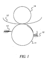
- Fig. 1 A coating solution is filled into a feed pan 10.
- the gravure coating method utilizes an engraved gravure cylinder 11 to apply a coating composition on to a web 12.
- the engraving or cells oh the gravure cylinder 11, which retains the coating composition, is typically filled by immersion of the roll into the feed pan. Excess liquid is scraped off the surface of the gravure cylinder by means of a doctor blade 13, so that the cylinder delivers a precise amount of liquid from the cells to the web upon contact.
- the contact between the web and the gravure cylinder is aided by an impression roller 14, whose pressure and hardness can alter the nip footprint and hence transfer characteristics of the liquid from the cells to the web.
- process parameters that are used to affect the quality of the pattern include method of contacting the coating solution and the gravure cylinder, position and angle of the doctor blade, impression cylinder pressure and coating speed.
- the coating solution does not flow after coating on the imaging element. Therefore the dimensional requirements for the discontinuous overcoat also apply to engraved gravure cylinder.
- a suitable method of feeding the gravure cylinder maybe selected dependent on the fluid properties and the desired coating speed.
- the simplest device used is a pan feed, but is found to be limited at higher speeds, due to unmetered layers and recirculation flows. While a simple feedbar maybe be sufficient in feeding a uniform metered film to the cylinder, a pressurized doctor feed system maybe used for higher speeds and foam sensitive material.
- a free falling curtain as described in U.S. Patent No. 5,681,381 may be used at high speed to provide hydrodynamic assist and hence delay air entrainment.
- While the preferred doctor blade 13 maybe above a 9 o'clock position on the engraved cylinder, in cases when a pressurized doctor feed system is used the position may be at 3 to 5 o'clock. In the latter case, a reverse angle blade maybe used. In the former case a blade contact angle between 50 and 65 degrees is preferred, to achieve a distinct doctoring.
- the impression roller 14 used in the process has a flexible covering, made of a suitable material, and whose hardness may vary between 40 and 90 durometer.
- the pressure applied by air loading or mechanical stops controls the transfer characteristics, of the fluid on to the web.
- an electrostatic assist charge on the backer roller can be used to alter the transfer of the fluid as described in "Gravure Process and Technology", Gravure Association of America, Rochester, NY, 1991.
- the geometrical pattern with which the pattern is deposited on the photographic element depends on the engraved geometry as well as the amount of flow during and after the coating is made.
- the discontinuous coating will be laid down in a pattern, which constitutes a spatial repetition of a basic element of coated patches.
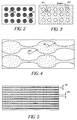
- Figures 2-5 show these patterns.
- the geometry of this pattern i.e., the shape, size and spatial frequency will affect the following factors 1) The quality of the image, 2) The rates of the various steps in the processing chemistry and 3) the ability to fuse and form a continuous overcoat.
- Figures 2-5 Some of the fundamental geometrical patterns that can exist in a discontinuous overcoat are shown in Figures 2-5.
- Figure 2 shows where the polymer is laid down as discrete patches and resemble islands within the surface of the imaging elements.
- Figure 3 shows where the islands are uncoated areas and the rest of the area is covered by the polymer.
- Figure 4 show a pattern in which neither the coated nor the uncoated areas are present as discrete patches but each forms a continuous domain. The two continuous area domains coexist, hence this is called bicontinuous.
- Figure 5 shows a pattern in which the polymer is laid down parallel stripes, another example of a bicontinuous pattern.
- the common property of these geometries is that the surface of the imaging element, that is furthest away from the support, is partially covered by a polymer.
- the percent area of the surface that is covered by the polymer can vary anywhere from 2 to 98 %.
- the spatial frequency be greater than 1000 patches/in 2 .
- the thickness of the polymer patch should be less than 500 ⁇ m, so that the optical properties of the surface of the imaging element is not altered substantially.
- the ratio of the covered to uncovered, Ar is limited by the area required to swell and transport processing chemicals into and out of the imaging element.
- Ar can vary from 1:49 to 49:1, depending on the permeability of the polymer coating under processing conditions.
- the total coverage of the polymer (based on the total area), Pc, is determined by the needs of the post coalesced coatings.
- the mean polymer laydown should be at least 0.11 g/m 2 over the entire surface area of the imaging element and in order to maintain the image quality, no more the 5.38 g/m 2 .
- Vc volume of fluid/unit area, that is to be deposited in the covered areas
- Cp is the concentration of the polymer in the coating melt in mg/ml and PI is the number of patches per unit area.
- the distance between patches should be such that post process coalescence is possible, and therefore, not greater than 1mm.
- One method of engraving the gravure cylinder to obtain a geometrical pattern of discrete polymer patches is to use a diamond shaped engraving stylus.
- the stylus is plunged into and out of the surface of the gravure cylinder to create a series of cells at a given spatial frequency.
- the dimensions of each engraved cell is determined by the shape of the stylus and the distance separating the cells is determined by the spatial frequency.
- Geometrical patterns where the uncoated areas are discrete are obtained from similar patterns as described above. In this case the shortest distance between edges of adjacent cells are smaller than 10 ⁇ m. Upon coating the solution flows between these edges, thus making the polymer continuous.
- One way of obtaining a striped pattern of the polymer on the surface of the photographic element as shown in Figure 5, is by use of a gravure cylinder engraved with a tri-helical geometry.
- An engraving tool is used to deform the surface of the gravure cylinder forming grooves that run around the circumference of the cylinder with a constant screw angle to form the helix.
- the actual pattern is composed of three helices with a constant phase angle between the helices.
- the tool angle which is related to the shape of the engraving tool, determines the shape of the groove and the volume of the fluid that the engraving carries. After the engraving has been carried out the surface of the gravure cylinder may be ground down.
- the fluid properties of the coating solution affect the quality of the transfer of the pattern.
- the viscosity of the solution should be high enough that upon deposition of the fluid, it does not flow substantially.
- the viscosity of the solution at shear rate less than 1 s -1 should be greater than 200 cp.
- the viscosity at this shear rate should be sufficiently high such that the fluid elements in any part of the pattern do not flow and join the fluid element of another part of the pattern. If this happens the phenomenon is commonly called "ribbing".
- the viscosity of the coating solution at a shear rate greater than 1000 s -1 should be greater than 50cp.
- a fibbed type of pattern can be obtained by maintaining a low viscosity at the high shear rates.
- thickening agents In order to achieve the desired rheology of the coating solutions containing the polymer, thickening agents, well known in the trade can be employed.
- water soluble polymers are commonly used as thickening agents.
- thickening agents are cellulosic materials such as carboxymethylcellulose, natural or synthetic polysaccharides such as xanthan gum, guar gum, locust bean gum, carageenan, konjac mannan, etc.
- Other water soluble thickeners include gelatin, polyvinyl pyrollidone, polyacrylamide, polyvinyl alcohol, polystyrene sulfonate and other water soluble polymers.
- suitable viscosifiers include organic soluble polymers such as poly methylmethacrylate, polydimethylsiloxane, cellulose acetate propionate.
- the fluid should also fill the etched cylinder, uniformly. Additionally, the web should be easily wet by the fluid otherwise the individual fluid elements will bead up. This can be accomplished by addition of appropriate surfactants at the appropriate concentrations.
- surfactants that can be used for aqueous systems are sodium diisopropylnaphthalene sulfonate, sodium dodecylbenzene sulfonate, TX200, Olin 10G etc.
- surfactants that can be used for organic solvent coatings can be FC430, DC510, FC170 etc.
- polymer solutions/dispersions used in this invention can be selected from, for example, polymers of alkyl esters of acrylic or methacrylic acid such as methyl methacrylate, ethyl methacrylate, butyl methacrylate, ethyl acrylate, butyl acrylate, hexyl acrylate, n-octyl acrylate, lauryl methacrylate, 2-ethylhexyl methacrylate, nonyl acrylate, benzyl methacrylate, the hydroxyalkyl esters of the same acids such as 2-hydroxyethyl acrylate, 2-hydroxyethyl methacrylate, and 2-hydroxypropyl methacrylate, the nitrile and amides of the same acids such as acrylonitrile, methacrylonitrile, and methacrylamide, vinyl acetate, vinyl propionate, vinylidene chloride, vinyl chloride, and vinyl aromatic compounds such as styrene
- Suitable polymers containing carboxylic acid groups include polymers derived from acrylic monomers such as acrylic acid, methacrylic acid, ethacrylic acid, itaconic acid, maleic acid, fumaric acid, monoalkyl itaconate including monomethyl itaconate, monoethyl itaconate, and monobutyl itaconate, monoalkyl maleate including monomethyl maleate, monoethyl maleate, and monobutyl maleate, citraconic acid, and styrenecarboxylic acid.
- acrylic monomers such as acrylic acid, methacrylic acid, ethacrylic acid, itaconic acid, maleic acid, fumaric acid, monoalkyl itaconate including monomethyl itaconate, monoethyl itaconate, and monobutyl itaconate, monoalkyl maleate including monomethyl maleate, monoethyl maleate, and monobutyl maleate, citraconic acid, and styrenecarboxylic acid
- polymers include ethyl cellulose, nitrocellulose , linseed oil-modified alkyd resins, rosin-modified alkyd resins, phenol-modified alkyd resins, phenolic resins, polyesters, poly(vinyl butyral), polyisocyanate resins, polyurethanes, polyamides, chroman resins, dammar gum, ketone resins, maleic acid resins, poly(tetrafluoroethylene-hexafluoropropylene), low-molecular weight polyethylene, phenol-modified pentaerythritol esters, copolymers with siloxanes and polyalkenes. These polymers can be used either alone or in combination. The polymers may be crosslinked or branched.
- the coating composition is composed of a mixture of high (B) and low (A) Tg polymers.
- the low Tg polymer A having a Tg less than 30 °C, is present in the patches in an amount of from 5 to 70 percent by weight and preferably from 10 to 50 percent by weight based on the total weight of the discontinuous layer.
- An aqueous coating formulation of 3% by weight of the colloidal polymer free of organic solvent or coalescing aid, is applied to a subbed sheet of polyethylene terephthalate in a wet coverage of 10 ml/m 2 and dried for 30 minutes at 30°C.
- Polymers that form clear, transparent continuous films under these conditions are low Tg and film-forming, while those that do not form clear, transparent continuous films are high Tg and non-film-forming at room temperature, for the purpose of this invention.
- the high Tg polymer (B), having a Tg greater than 30 °C comprises glassy polymers that provide resistance to blocking, ferrotyping, abrasion and scratches.
- High Tg polymer B is present in the coating composition and in the overcoat layer in an amount of from 30 to 80 and preferably from 50 to 70 percent based on the total weight of low Tg polymer (A) and high Tg polymer (B).
- polymers include addition-type polymers and interpolymers prepared from ethylenically unsaturated monomers such as acrylates including acrylic acid, methacrylates including methacrylic acid, acrylamides and methacrylamides, itaconic acid and its half esters and diesters, styrenes including substituted styrenes, acrylonitrile and methacrylonitrile, vinyl acetates, vinyl ethers, vinyl and vinylidene halides, and olefins.
- ethylenically unsaturated monomers such as acrylates including acrylic acid, methacrylates including methacrylic acid, acrylamides and methacrylamides, itaconic acid and its half esters and diesters, styrenes including substituted styrenes, acrylonitrile and methacrylonitrile, vinyl acetates, vinyl ethers, vinyl and vinylidene halides, and olefins.
- crosslinking and graft-linking monomers such as 1,4-butyleneglycol methacrylate, trimethylolpropane triacrylate, allyl methacrylate, diallyl phthalate, divinyl benzene, and the like may be used.
- Other polymers that may comprise component B include water-dispersible condensation polymers such as polyesters, polyurethanes, polyamides, and epoxies. Polymers suitable for component B do not give transparent, continuous films upon drying at temperatures below 30°C when the above-described test is applied.
- the low Tg polymer (A) comprises polymers that form a continuous film under the extremely fast drying conditions typical of the photographic film manufacturing process.
- Polymers that are suitable for component A are those that give transparent, continuous films when the above-described test is applied and include addition-type polymers and interpolymers prepared from ethylenically unsaturated monomers such as acrylates including acrylic acid, methacrylates including methacrylic acid, acrylamides and methacrylamides, itaconic acid and its half esters and diesters, styrenes including substituted styrenes, acrylonitrile and methacrylonitrile, vinyl acetates, vinyl ethers, vinyl and vinylidene halides, and olefins.
- crosslinking and graft-linking monomers such as 1,4-butyleneglycol methacrylate, trimethylolpropane triacrylate, allyl methacrylate, diallyl phthalate, divinyl benzene, and the like may be used.
- Other suitable polymers useful as component A are low Tg dispersions of polyurethanes or polyesterionomers.
- a preferred polymeric material is one that would allow some degree of permeability through the patch itself
- One such preferred polymer is a hybrid urethane-vinyl copolymer having an acid number of greater than or equal to 5 and less than or equal to 30. Acid number is in general determined by titration and is defined as the number of milligrams of potassium hydroxide (KOH) required to neutralize 1 gram of the polymer.
- KOH potassium hydroxide
- Polyurethanes provide advantageous properties such as good film-formation, good chemical resistance, abrasion-resistance, toughness, elasticity and durability.
- polyester based urethanes exhibit high levels of tensile and flexural strength, good abrasion resistance and resistance to various oils.
- Acrylics have the added advantage of good adhesion, non-yellowing, adjustable for high gloss and a wide range of glass transition (Tg) and minimum film forming temperatures.
- the urethane vinyl hybrid polymers are very different from blends of the two. Polymerization of the vinyl monomer in the presence of the polyurethane causes the two polymers to reside in the same latex particle as an interpenetrating or semi-interpenetrating network resulting in improved resistance to water, organic solvents and environmental conditions, improved tensile strength and modulus of elasticity.
- the presence of acid groups such as carboxylic acid groups provide a conduit for processing solutions to permeate the patches at high pH. Maintaining the acid number greater than 30 ensures that the overcoat has good adhesion to the substrate below even at high pH and makes the overcoat more water resistant.
- the overcoat layer formed after coalescing the patches in accordance with this invention is particularly advantageous due to superior physical properties including excellent resistance to water, fingerprinting, fading and yellowing, exceptional transparency and toughness necessary for providing resistance to scratches, abrasion, blocking, and ferrotyping.
- the discontinuous polymer coating should be clear, i.e., transparent, and preferably colorless. But it is specifically contemplated that the coated areas can have some color for the purposes of color correction, or for special effects, so long as the image is viewable through the overcoat. Thus, there can be incorporated into the polymer dye which will impart color. In addition, additives can be incorporated into the coating formulation which will give to the overcoat desired properties. For example, a UV absorber can be incorporated into the polymer particle to make the overcoat UV absorptive, thus protecting the image from UV induced fading.
- additional compounds may be added to the coating composition, depending on the functions of the particular layer, including surfactants, emulsifiers, coating aids, lubricants, matte particles, rheology modifiers, crosslinking agents, antifoggants, inorganic fillers such as conductive and nonconductive metal oxide particles, pigments, magnetic particles, biocide, and the like.
- the coating composition may also include a small amount of organic solvent, preferably the concentration of organic solvent is less than 1 percent by weight of the total coating composition. The invention does not preclude coating the desired polymeric material from a volatile organic solution or from a melt of the polymer.
- coating aids include any soluble polymer or other material that imparts appreciable viscosity to the coating suspension at rest and shear thinning otherwise, such as high MW polysaccharide derivatives (e.g. xanthan gum, guar gum, gum acacia, Keltrol (an anionic polysaccharide supplied by Merck and Co., Inc.) high MW polyvinyl alcohol, carboxymethylcellulose, hydroxyethylcellulose, polyacrylic acid and its salts, polyacrylamide, etc).
- surfactants include any surface active material that will lower the surface tension of the coating preparation sufficiently to prevent edge-withdrawal, repellencies, and other coating defects.
- alkyloxy- or alkylphenoxypolyether or polyglycidol derivatives and their sulfates such as nonylphenoxypoly(glycidol) available from Olin Matheson Corporation or sodium octylphenoxypoly(ethyleneoxide) sulfate, organic sulfates or sulfonates, such as sodium dodecyl sulfate, sodium dodecyl sulfonate, sodium bis(2-ethylhexyl)sulfosuccinate (Aerosol OT), and alkylcarboxylate salts such as sodium decanoate.
- alkyloxy- or alkylphenoxypolyether or polyglycidol derivatives and their sulfates such as nonylphenoxypoly(glycidol) available from Olin Matheson Corporation or sodium octylphenoxypoly(ethyleneoxide) sulfate, organic sulfates or sulf
- the step of transforming the discontinuous overcoat into the continuous one is termed as a "fusing" step.
- the reduced aqueous permeability afforded by the discontinuous overcoat would not require a fusing step.
- the fusing step can be carried out by several means.
- the final step includes drying the imaged element in a dryer at elevated temperature. Depending on the Tg of the polymer and its melt viscosity characteristics, the temperature in the dryer can be adjusted such that fusing occurs.
- Another method of fusing during the photoprocessing step is to add a coalescing aid at one step within the photoprocessing operation.
- the coalescing aid will be added to the last wet operation, i.e., the wash step.
- the coalescing aids that can be added to the wash water are aqueous soluble glycol ethers such as Dowanol.
- the fusing step can be accomplished chemically as described or in a combination of a heat and pressure application step.
- a belt or roller fuser device may be used to apply heat and pressure to the imaged element.
- the Tg of the underlying gelatin matrix would be lower or close to that of the polymer itself.
- the problem that is encountered in the fusing step is that the discrete areas coated with the polymer sink into the gelatin matrix rather than deform laterally.
- the deformation of the underlying gelatin matrix may prevent complete fusion of the overcoat.
- a specific geometrical pattern that would distribute the pressure and minimize the deformation of the gelatin would enable the overcoat to fuse.
- the special case of a parallel striped pattern would be preferred to aid fusing.
- the striped pattern is expected to distribute the applied fusing pressure evenly.
- the distance of polymer flow is uniform throughout the whole pattern.
- the surface characteristics of the overcoat are in large part dependent upon the physical characteristics of the polymers which form the continuous phase and the presence or absence of solid, nonfusible particles.
- the surface characteristics of the overcoat also can be modified by the conditions under which the surface is fused.
- the surface characteristics of the fusing element that is used to fuse the polymers to form the continuous overcoat layer can be selected to impart a desired degree of smoothness, texture or pattern to the surface of the element.
- a highly smooth fusing element will give a glossy surface to the imaged element
- a textured fusing element will give a matte or otherwise textured surface to the element
- a patterned fusing element will apply a pattern to the surface of the element, etc.
- additives which will modify the surface characteristics of the element.
- additives include lubricants, surfactants (including fluorinated surfactants), dispersing aids, coating aids, thickeners, crosslinking agents or hardeners, soluble and/or solid particle dyes, antifoggants, matte particles, inorganic particles, like silica, and others.
- a plasticizer is a substance or material incorporated in the polymer melt to increase its flexibility, workability or extensibility.
- a plasticizer usually reduces the melt viscosity, lowers the temperature of a second order transition or lowers the elastic modulus of the polymer.
- plasticizers examples include esters of phthalic acid, phosphoric acid, aliphatic diacids or liquid polymers or oligomers with a relatively low glass transition temperature and include phthalates, adipates, trimellitates, benzoic acid esters, azelates, isobutyrates, glutarate esters, citrate esters, petroleum oils, mineral oils, and phosphate esters. Additional plasticizers can be selected from those described by Sears, J. K. and Darby, J. R. in The Technology of Plasticizers (John Wiley & Sons, NY 1982).
- plasticizers include di-2-ethylhexyl terephthalate, di-2-ethylhexyl phthalate (DOP), dibutyl phthalate (DBP), ditridecylphthalate (DTP), dioctyl terephthalate, butyl benzyl phthalate (BBP), dipropylene glycol dibenzoate, di-n-butyl azelate, di-n-hexyl azelate, di-2-ethylhexyl azelate, 2,2,4-trimethyl-1,3-pentanediol, diisodecyl glutarate, triethyl citrate, triaryl phosphate ester, tricresyl phosphate (TCP), diocty adipate (DOA), alkyl diaryl phosphates, glycol ethers such as Texanol and Dowanol and many others known to a person of ordinary skill
- plasticizer The amount of plasticizer required depends on the properties of the polymer, such as Tg and molecular weight, and its chemical identity. Levels of plasticizer up to 50% of the total polymer present may be used. Careful choice of the type and amount of plasticizer is critical because excessive amounts of plasticizer will degrade the desired mechanical properties of the overcoat.
- the plasticizers can be added directly to the suspension and it can be loaded into the latex particles by simple mixing.
- the plasticizer can be added directly to the melt.
- the plasticizer can be incorporated during the synthesis of the polymer.
- the imaged photographic elements protected in accordance with this invention are derived from silver halide photographic elements that can be black and white elements (for example, those which yield a silver image or those which yield a neutral tone image from a mixture of dye forming couplers), single color elements or multicolor elements.
- Multicolor elements typically contain dye image-forming units sensitive to each of the three primary regions of the spectrum.
- the imaged elements can be imaged elements which are viewed by transmission, such a negative film images, reversal film images and motion picture prints or they can be imaged elements that are viewed by reflection, such as paper prints. Because of the amount of handling that can occur with paper prints and motion picture prints, they are the preferred imaged photographic elements for use in this invention.
- a typical multicolor photographic element comprises a support bearing a cyan dye image-forming unit comprised of at least one red-sensitive silver halide emulsion layer having associated therewith at least one cyan dye-forming coupler, a magenta dye image-forming unit comprising at least one green-sensitive silver halide emulsion layer having associated therewith at least one magenta dye-forming coupler, and a yellow dye image-forming unit comprising at least one blue-sensitive silver halide emulsion layer having associated therewith at least one yellow dye-forming coupler.
- the element can contain additional layers, such as color filter layers, interlayers, overcoat layers, subbing layers, and the like. All of these can be coated on a support which can be transparent (for example, a film support) or reflective (for example, a paper support).
- Photographic elements protected in accordance with the present invention may also include a magnetic recording material as described in Research Disclosure , Item 34390, November 1992, or a transparent magnetic recording layer such as a layer containing magnetic particles on the underside of a transparent support as described in US 4,279,945 and US 4,302,523.
- a two station gravure machine was used to coat the desired discontinuous coating on a photographic element.
- the photographic element used to demonstrate the current invention was a tricolor multilayered element, containing light sensitive silver halide layers coated on a reflective paper support.
- the face width of the engraved gravure cylinder and impression cylinder corresponded with the width of the web at 14".
- the gravure cylinder was made of a stainless steel base with a copper plating and had a diameter of 10".
- the engravings were made electromechanically by using a diamond tip engraving tool or stylus.
- the engraving tool is characterized by the stylus angle, which is the angle made by the apex of the diamond and controls the ratio of the width to the depth of the cell.
- the engraving geometry is defined by the shape of each cell and the spacing between cells.
- the compression angle defines the ratio of the vertical repeat length to the horizontal repeat length.
- the coating process utilized a typical direct gravure setup, which comprised of (i) a simple pan feed, filled up to the required level for filling the cells, (ii) a standard clamped doctor blade holder using an 8 mil thick blade at a 35 degree application and an attack angle of 55 deg. to the tangent at the point of application, (iii) and a 70 durometer (hardness) backer roller.
- the dryer temperature was set to 180 deg F.
- the polymer used to demonstrate this invention was an acrylic polymer dispersion NeoCryl A-5090 from Zeneca Resins.
- the polymer has a minimum film forming temperature of 6°C.
- a second polymer used was a urethane/acrylic copolymer NeoCryl R-9699.
- the coating solution of both polymers consisted of 40 parts by weight of the polymer latex suspension. As part of the variations, the solutions were used with and without various thickening agents added.
- the thickening agents used were Keltrol T (Xanthan gum) and poly vinyl pyrrolidone K90 from BASF. All solutions had 0.1% of Olin 10G surfactant added as a coating aid to reduce surface tension.
- the rheological characteristics of the various coating solutions were measured using a Haake rheometer and measured at room temperature.
- the following polymer solutions were used to coat:
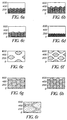
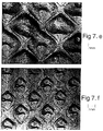
- the above table shows that by varying the coating speed and the rheology of the coating solutions it is possible to form a discontinuous overcoat in a desired pattern that is engraved on the cylinder. Furthermore the desired rheology can be achieved by using a single thickening agent (as in example 2) or by using a combination of thickening agents (as in example 4).
- a coating corresponding to the pattern shown in Figure 5 was produced as follows.
- the face width of the engraved gravure cylinder and impression cylinder corresponded with the width of the web at 14".
- the gravure cylinder was made of a stainless steel base with a copper plating and had a diameter of 10".
- the gravure cylinder was engraved with a hardened steel triangular engraving tool.
- the engraving had 230 lines per inch engraved at 45° angle to the axis of the cylinder. Each line was 20 microns deep, 90 microns cell width (width of the stripe) on top and 19 microns land width (distance between stripes).
- the volume engraved was 0.71cc/ft 2 of surface area. It was assumed, based on knowledge in the art of gravure coating, that approximately half the volume of fluid is transferred from the cells on to the web.
- the polymer used to demonstrate this invention was an acrylic polymer dispersion NeoCryl A-5090 from Zeneca Resins. It has an acid number of 11.
- Dibutyl phthalate was added to the latex, as a polymer plasticizer. The dibutyl phthalate was added directly into the latex dispersion at a level of 20% by weight with respect to the polymer.
- the coating solution was composed of 40 parts by weight of the polymer latex suspension, 0.2 parts by weight of Keltrol T (xanthan gum), 0.5 parts by weight of poly vinyl pyrolidone (Luviskol K90, made by BASF), 0.1 parts by weight of Olin 10G surfactant and the rest was water.
- the gravure coating machine was set up as follows: the blade load was set at 8 psi, and the backer pressure at 10 psi for the coating, while a dryer temperature of 180 °F was found to be adequate for drying all the patch variations
- the coating strips were processed in RA4 chemistry. The coating strips were then passed through a roller fuser at 128 °C and a pressure of 23 psi. Water resistance of the overcoat was measured using an aqueous solution Ponceau Red dye which is known to stain gelatin through ionic interaction. Ponceau Red dye solution was prepared by dissolving 1 gram dye in 1000 grams mixture of acetic acid and water (5 parts:95 parts). The water permeability was done by placing a drop of the dye solution on the sample for 10 minutes followed by a 30-second water rinse to remove excess dye solution on the coating surface. Each sample was then air dried, and status A reflectance density on the spotted area was recorded.
- Ponceau Red dye solution was prepared by dissolving 1 gram dye in 1000 grams mixture of acetic acid and water (5 parts:95 parts). The water permeability was done by placing a drop of the dye solution on the sample for 10 minutes followed by a 30-second water rinse to remove excess dye solution on the coating surface. Each sample was then air dried, and status A
Landscapes
- Chemical & Material Sciences (AREA)
- Engineering & Computer Science (AREA)
- Materials Engineering (AREA)
- Physics & Mathematics (AREA)
- General Physics & Mathematics (AREA)
- Life Sciences & Earth Sciences (AREA)
- Chemical Kinetics & Catalysis (AREA)
- General Chemical & Material Sciences (AREA)
- Pest Control & Pesticides (AREA)
- Application Of Or Painting With Fluid Materials (AREA)
Applications Claiming Priority (2)
| Application Number | Priority Date | Filing Date | Title |
|---|---|---|---|
| US313555 | 1999-05-14 | ||
| US09/313,555 US6303184B1 (en) | 1999-05-14 | 1999-05-14 | Method of forming a discontinuous polymer overcoat for imaging elements |
Publications (1)
| Publication Number | Publication Date |
|---|---|
| EP1052539A1 true EP1052539A1 (fr) | 2000-11-15 |
Family
ID=23216201
Family Applications (1)
| Application Number | Title | Priority Date | Filing Date |
|---|---|---|---|
| EP00201593A Withdrawn EP1052539A1 (fr) | 1999-05-14 | 2000-05-03 | Procédé de fabrication d' une couche protectrice polymérique discontinue pour éléments formant image |
Country Status (3)
| Country | Link |
|---|---|
| US (1) | US6303184B1 (fr) |
| EP (1) | EP1052539A1 (fr) |
| JP (1) | JP2000347347A (fr) |
Families Citing this family (8)
| Publication number | Priority date | Publication date | Assignee | Title |
|---|---|---|---|---|
| JP2001030611A (ja) * | 1999-07-27 | 2001-02-06 | Nihon Tokkyo Kanri Co Ltd | 水性グラビアインキを用いて行うグラビア印刷方法及びこの印刷方法の実施に用いられる版胴並びにこの印刷方法により印刷された印刷物 |
| US6853587B2 (en) * | 2002-06-21 | 2005-02-08 | Micron Technology, Inc. | Vertical NROM having a storage density of 1 bit per 1F2 |
| US20060092495A1 (en) * | 2004-10-28 | 2006-05-04 | Fuji Photo Film Co., Ltd. | Anti-glare anti-reflection film, polarizing plate, and image display device |
| US8372912B2 (en) | 2005-08-12 | 2013-02-12 | Eastman Chemical Company | Polyvinyl chloride compositions |
| CN102850968B (zh) | 2006-08-30 | 2015-09-09 | 伊士曼化工公司 | 乙酸乙烯酯聚合物组合物中作为增塑剂的对苯二甲酸酯 |
| WO2008027463A1 (fr) * | 2006-08-30 | 2008-03-06 | Eastman Chemical Company | Compositions d'agent d'étanchéité comprenant un nouveau plastifiant |
| KR20110073873A (ko) * | 2009-12-24 | 2011-06-30 | 엘지이노텍 주식회사 | 패턴롤 및 이를 이용한 패턴형성장치 |
| US9393823B2 (en) | 2012-08-08 | 2016-07-19 | Color Communications, Inc. | Color fan deck with paper blades painted on both sides |
Citations (4)
| Publication number | Priority date | Publication date | Assignee | Title |
|---|---|---|---|---|
| US4113903A (en) * | 1977-05-27 | 1978-09-12 | Polaroid Corporation | Method of multilayer coating |
| EP0414015A2 (fr) * | 1989-08-03 | 1991-02-27 | Kimberly-Clark Corporation | Bande de tissu, fabrication et emploi |
| US5368894A (en) * | 1993-06-08 | 1994-11-29 | Minnesota Mining And Manufacturing Company | Method for producing a multilayered element having a top coat |
| WO1995026270A1 (fr) * | 1994-03-28 | 1995-10-05 | Rexam Industries Corp. | Rouleau de couchage par gravure et procede permettant d'obtenir un gradient de revetement uniforme |
Family Cites Families (36)
| Publication number | Priority date | Publication date | Assignee | Title |
|---|---|---|---|---|
| US2331746A (en) | 1943-10-12 | Anti-abrasion coating for photographic | ||
| GB466879A (en) | 1935-08-22 | 1937-06-07 | Ig Farbenindustrie Ag | Improvements relating to photographic materials |
| US2259009A (en) | 1938-11-23 | 1941-10-14 | Eastman Kodak Co | Antiabrasion coating for photographic film |
| US2706686A (en) | 1952-10-01 | 1955-04-19 | Eastman Kodak Co | Method of lacquering photographic emulsions and products produced thereby |
| US2798004A (en) | 1954-01-26 | 1957-07-02 | Eastman Kodak Co | Film lacquer |
| US3113867A (en) | 1959-10-29 | 1963-12-10 | Eastman Kodak Co | Motion-picture film lacquer |
| US3190197A (en) | 1960-08-11 | 1965-06-22 | Eastman Kodak Co | Protective colloidal silica lacquer for developed photographic prints |
| US3397980A (en) | 1964-06-01 | 1968-08-20 | Ncr Co | Protective laminate for film containing silver micro-image |
| DE1202136B (de) | 1964-06-04 | 1965-09-30 | Agfa Ag | Photographisches Material mit einer aussen angeordneten, eine rauhe Oberflaeche besitzenden Schutzschicht |
| US3415670A (en) | 1965-04-01 | 1968-12-10 | Mcdonald Photo Products Inc. | Method and composition for surface finishing photographs or the like |
| FR1499022A (fr) | 1966-11-14 | 1967-10-20 | Fotochem Werke Berlin Veb | Procédé de fabrication de couches auxiliaires pour matières photographiques à base de polymères synthétiques |
| US3508947A (en) | 1968-06-03 | 1970-04-28 | Eastman Kodak Co | Method for simultaneously applying a plurality of coated layers by forming a stable multilayer free-falling vertical curtain |
| US3697277A (en) | 1969-08-14 | 1972-10-10 | Phillips Petroleum Co | Nonglare photographic prints |
| US3733293A (en) | 1971-03-10 | 1973-05-15 | Eastman Kodak Co | Water and abrasion resistant coatings having low gloss from aqueous systems |
| US3936549A (en) | 1972-11-17 | 1976-02-03 | The Kohler Coating Machinery Corporation | Method and apparatus for applying a liquid coating to strip material |
| US4171979A (en) | 1976-11-01 | 1979-10-23 | Eastman Kodak Company | Method of treating scratched or abraded photographic elements with radiation-curable compositions comprising an acrylated urethane, an aliphatic ethylenically-unsaturated carboxylic acid and a multifunctional acrylate |
| US4092173A (en) | 1976-11-01 | 1978-05-30 | Eastman Kodak Company | Photographic elements coated with protective overcoats |
| FR2382325A1 (fr) | 1977-03-02 | 1978-09-29 | Kodak Pathe | Produit comprenant une couche d'enregistrement magnetique transparente |
| US4158333A (en) | 1978-05-01 | 1979-06-19 | Anpa Research Institute | Inking baffle for rotary newspaper presses |
| US4209584A (en) * | 1979-06-15 | 1980-06-24 | Eastman Kodak Company | Manufacture of photographic elements having anticurl and antistatic layers |
| US4373443A (en) | 1980-02-15 | 1983-02-15 | American Newspaper Publishers Association | Method of high viscosity inking in rotary newspaper presses |
| CA1172790A (fr) | 1980-11-24 | 1984-08-14 | Gerald M. Leszyk | Substance durcissable par rayonnement et comprenant un urethanne acryle, un acide carboxylique insture, un acrylate multifonctionnel et un siloxy- polycarbinol |
| US4426431A (en) | 1982-09-22 | 1984-01-17 | Eastman Kodak Company | Radiation-curable compositions for restorative and/or protective treatment of photographic elements |
| US4999266A (en) | 1986-04-18 | 1991-03-12 | Hoechst Celanese Corporation | Protected color image on substrate with thermal adhesive and antiblocking overlayers |
| US5179147A (en) | 1990-05-23 | 1993-01-12 | Eastman Kodak Company | Protective overcoat compositions and photographic elements containing same |
| JP3225380B2 (ja) | 1992-08-11 | 2001-11-05 | コニカ株式会社 | プリント写真の樹脂保護膜及びそれを用いた画像形成方法 |
| US5447832A (en) | 1994-03-31 | 1995-09-05 | Eastman Kodak Company | Imaging element |
| US5681381A (en) | 1995-12-11 | 1997-10-28 | Pitney Bowes Inc. | Fluorescent red and magenta waterfast ink jet inks |
| US5723273A (en) * | 1996-09-11 | 1998-03-03 | Eastman Kodak Company | Protective overcoat for antistatic layer |
| US5853965A (en) | 1997-05-23 | 1998-12-29 | Eastman Kodak Company | Photographic element with bonding layer on oriented sheet |
| US5866282A (en) | 1997-05-23 | 1999-02-02 | Eastman Kodak Company | Composite photographic material with laminated biaxially oriented polyolefin sheets |
| US5874205A (en) | 1997-05-23 | 1999-02-23 | Eastman Kodak Company | Photographic element with indicia on oriented polymer back sheet |
| US5888683A (en) | 1997-05-23 | 1999-03-30 | Eastman Kodak Company | Roughness elimination by control of strength of polymer sheet in relation to base paper |
| US5888643A (en) | 1997-05-23 | 1999-03-30 | Eastman Kodak Company | Controlling bending stiffness in photographic paper |
| US5888681A (en) | 1997-05-23 | 1999-03-30 | Eastman Kodak Company | Photographic element with microvoided sheet of opalescent appearance |
| US5888714A (en) | 1997-12-24 | 1999-03-30 | Eastman Kodak Company | Adhesives such as metallocene catalyzed ethylene plastomers for bonding biaxially oriented polyolefin sheets to paper |
-
1999
- 1999-05-14 US US09/313,555 patent/US6303184B1/en not_active Expired - Fee Related
-
2000
- 2000-05-03 EP EP00201593A patent/EP1052539A1/fr not_active Withdrawn
- 2000-05-15 JP JP2000142506A patent/JP2000347347A/ja active Pending
Patent Citations (4)
| Publication number | Priority date | Publication date | Assignee | Title |
|---|---|---|---|---|
| US4113903A (en) * | 1977-05-27 | 1978-09-12 | Polaroid Corporation | Method of multilayer coating |
| EP0414015A2 (fr) * | 1989-08-03 | 1991-02-27 | Kimberly-Clark Corporation | Bande de tissu, fabrication et emploi |
| US5368894A (en) * | 1993-06-08 | 1994-11-29 | Minnesota Mining And Manufacturing Company | Method for producing a multilayered element having a top coat |
| WO1995026270A1 (fr) * | 1994-03-28 | 1995-10-05 | Rexam Industries Corp. | Rouleau de couchage par gravure et procede permettant d'obtenir un gradient de revetement uniforme |
Also Published As
| Publication number | Publication date |
|---|---|
| JP2000347347A (ja) | 2000-12-15 |
| US6303184B1 (en) | 2001-10-16 |
Similar Documents
| Publication | Publication Date | Title |
|---|---|---|
| US6300045B2 (en) | Polymer overcoat for imaging elements | |
| EP0191302B1 (fr) | Procédé pour appliquer des compositions antistatiques en deux couches sur des supports en polyester | |
| EP0893735B1 (fr) | Particules plastiques pré-enduites, fusionnées comme couche protectrice pour épreuves photographiques | |
| US5856051A (en) | Water-resistant protective overcoat for AgX photographic system | |
| JP2002174878A (ja) | 画像が形成された要素及びその作製方法 | |
| CN1304059A (zh) | 具有挤出抗静电层的反射正片材料 | |
| US6303184B1 (en) | Method of forming a discontinuous polymer overcoat for imaging elements | |
| US6077648A (en) | Protective overcoat for photographic elements | |
| US6077656A (en) | Photographic paper backing containing polymeric primary amine addition salt | |
| US6194130B1 (en) | Protective overcoat comprising polyvinyl alcohol for photographic elements | |
| JP2000330240A (ja) | 写真印画紙用帯電防止バッキング | |
| DE60000209T2 (de) | Antistatische Schicht für ein elektrisch leitendes Polymer und modifizierte Gelatine enthaltendes bildgebendes Element | |
| EP0829756A2 (fr) | Composition de revêtement pour éléments d'enregistrement d'image comprenant du chlorure de vinylidène | |
| US6232049B1 (en) | Protective overcoat for photographic elements | |
| EP0421764A1 (fr) | Support pour papier de tirage photographique | |
| JP2002006446A (ja) | 写真要素のためのポリエステルイオノマーを含んでなる保護オーバーコート | |
| JP2002148758A (ja) | 初期の耐水性保護オーバーコートを有する写真要素 | |
| EP1052543A1 (fr) | Couche de substratage pour élément photographique | |
| JPS634231A (ja) | 写真印画紙用支持体 | |
| DE69603675T2 (de) | Bildherstellungselement enthaltend eine elektrisch leitende Schicht und eine Schutzschicht enthaltend in Lösungsmitteln dispergierbare polymere Teilchen | |
| EP0752619B1 (fr) | Films donneur et accepteur d'images colorées pour le procédé par imbibition de colorant | |
| US6153362A (en) | Overcoat for reticulation control in photographic elements | |
| JP2000284418A (ja) | 写真要素 | |
| JP2000284420A (ja) | 写真要素 | |
| EP0487790A1 (fr) | Méthode pour réguler la blancheur et film pelliculable |
Legal Events
| Date | Code | Title | Description |
|---|---|---|---|
| PUAI | Public reference made under article 153(3) epc to a published international application that has entered the european phase |
Free format text: ORIGINAL CODE: 0009012 |
|
| AK | Designated contracting states |
Kind code of ref document: A1 Designated state(s): DE FR GB |
|
| AX | Request for extension of the european patent |
Free format text: AL;LT;LV;MK;RO;SI |
|
| 17P | Request for examination filed |
Effective date: 20010430 |
|
| AKX | Designation fees paid |
Free format text: DE FR GB |
|
| 17Q | First examination report despatched |
Effective date: 20031124 |
|
| STAA | Information on the status of an ep patent application or granted ep patent |
Free format text: STATUS: THE APPLICATION IS DEEMED TO BE WITHDRAWN |
|
| 18D | Application deemed to be withdrawn |
Effective date: 20040405 |